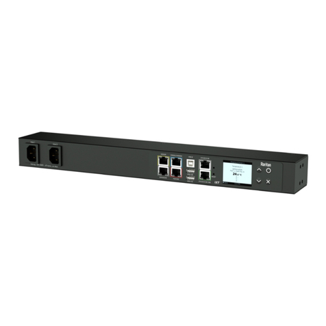
Catalogue number(s): 0 488 51
2-output DALI controller
Technical data sheet: S000067167EN-3 Updated on: 24/08/2015 Created on: 10/01/2012
5/5
CONTENTS
7. PARAMETER SETTING
When connecting the detector(s) to the controller it must be switched
off.
Switching the controller on generates an automatic configuration
between the detector(s) and the controller.
The controller carries out a Plug’n Go procedure, analyses the
detectors on the BUS SCS then, if necessary, configures them.
It is still possible to reset the assembly, as follows:
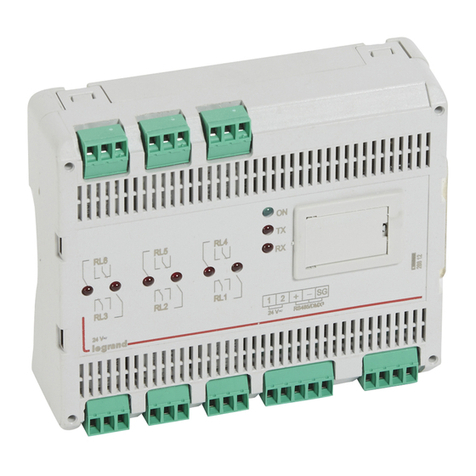
- Short press on the Reset button on the controller: the RESET LED
flashes slowly
- Long press on the Reset button: the RESET LED starts to flash after
10 seconds. The controller deletes all the detectors connected to it,
then reconfigures itself and the detectors
- When the RESET LED goes off, the system is ready to operate
The detectors are configured in walk-through mode, with a 15 minute
time delay and a light level of 500 lux.
The parameters of the detector can be set using the configuration
tools Cat. No. 0 882 35 (simplified configuration tool) or
Cat. No. 0 882 30 (advanced configuration tool).
Consult the relevant technical data sheets for detailed parameter
setting of compatible digital detectors.
8. MAINTENANCE
Do not use: acetone, tar-removing cleaning agents or
trichloroethylene.
Maintenance with the following products: - Hexane (En 60669-1)
- Methylated spirit
- Soapy water
- Diluted ammonia
- Bleach diluted to 10%
- Window-cleaning products
9. STANDARDS
Directive: CE
Installation standards: NFC 15-100
Product standards: NF EN 50428
Environmental standards:
- EU Directive 2002/96/EC:
WEEE (Waste Electrical and Electronic Equipment)
- EU Directive 2002/95/EC:
RoHS (Restriction of Hazardous Substances)
- Regulations: ERP (public buildings)
ERT (workplace buildings)
IGH (high-rise buildings)
ATTENTION: An initial test is required for the use of other special
maintenance products.
Note: All technical information is available at
www.legrandoc.com
6. OPERATION (continued)
Detector
This controls the switching on and off of the two lighting circuits and
the change of state of the ventilation at the end of the time delay.
It regulates the two lighting channels automatically following a
sufficient contribution from outside light.
When the contribution from outside light decreases, the two lighting
circuits dim proportionally.
6.4 Choice of operating modes
The operating mode of the controller can be changed using the Reset
button.
A long press (> 400 ms) on the Reset button is used to scroll through
the operating modes. The modes are indicated using 3 LEDs, marked
1 to 3.
When the button has been pressed for 2 s, the LEDs start to flash,
indicating that the controller is switching to parameter setting mode.
Then a different mode is offered every 4 s. When you reach the mode
you want, simply release the Reset button. When the LEDs stop
flashing, the new mode has been selected.
6.5 Override
It is possible to override the electronic control box linking the two
channels by using the pushbuttons.
The resulting behaviour is given in the following table.
LED no. Operating mode
1234 Mode 1 Corridor side = window side + 30%
1234 Mode 2 Corridor side = window side + 50%
1234 Mode 3 Corridor side = window side + 80%
1234 Mode 4 Synchronised
1234 Mode 5 Surrounding area
Mode 1 = DA2 = DA1 + 30%
Mode 2 = DA2 = DA1 + 50%
Mode 3 = DA2 = DA1 + 80%
Mode 4 = DA2 = DA1
Mode 5 = DA2 = 2/3 DA1
MODE DA1
pushbutton
DA2
pushbutton
Mode 1 = DA2 = DA1 + 30%
ON/OFF ON/OFF
Mode 2 = DA2 = DA1 + 50%
Mode 3 = DA2 = DA1 + 80%
Mode 4 = DA2 = DA1 ON/OFF
Mode 5 = DA2 = 2/3 DA1 ON/OFF ON/OFF
