manuals.online logo
Brands
  1. Home
  2. •
  3. Brands
  4. •
  5. LEGRAND
  6. •
  7. Controllers
  8. •
  9. LEGRAND 5739 12 Instruction Manual

LEGRAND 5739 12 Instruction Manual

SCS BUS SYSTEM
1
TECHNICAL SHEET
P
PL
A
M
INT
LG00047-c-UK
Touch control
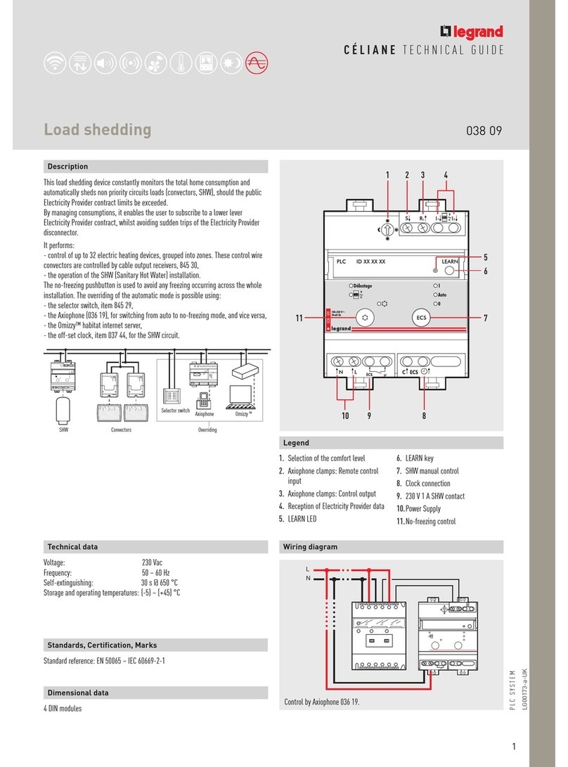
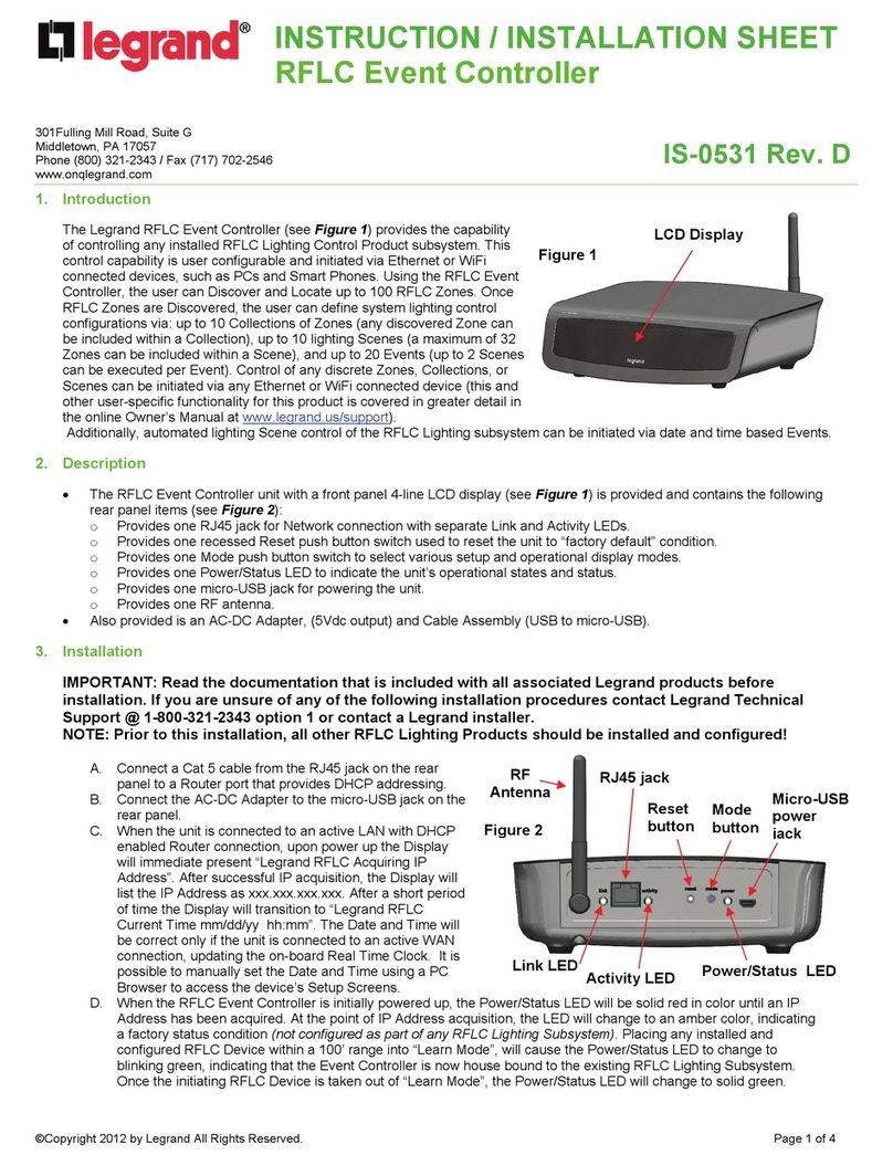
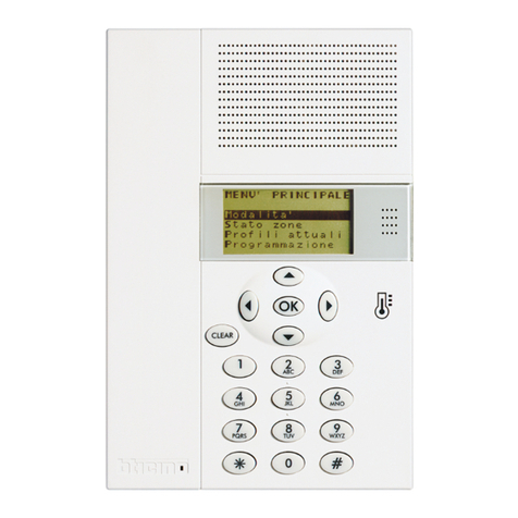
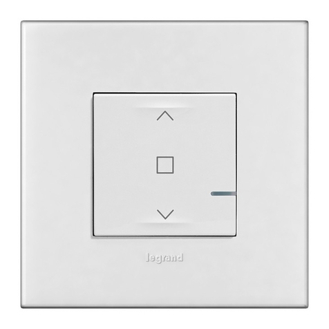
Description
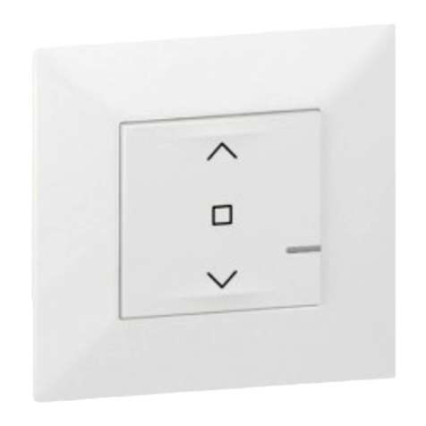
This control is a SCS control, which traditional pushbuttons are replaced by
capacitive sensors. Moving the finger close to a sensor is the same as pressing a
pushbutton.
The device can be used to perform the functions typical of a special SCS control by
simply moving a finger close to the surface. It is produced in the 3 module flush-
mounting version, 6 keys respectively. Each zone corresponding to a key is marked
at the centre by a light blue LED. When the user moves a finger close to the zone, its
intensity increases sensibly, and remains so until the finger is moved away again.
Therefore, the LEDs can have two different levels of light intensity. The brightness
level of the LEDs can be changed using the appropriate adjustment pushbutton.
The control may operate in four different modes: self-learning, scenarios, swivelling,
CEN.
- The self-learning mode (cyclic or non-cyclic) allows to associate to each key
most of the typical automation system, sound system, video door entry system
(staircase light, open-door, call to the floor, door lock, and cycling of cameras)
functions, in additional to auxiliary controls.
- The scenario mode can be used to recall, program and delete 6 scenarios of a
scenario module.
-The swivelling mode can be used to drive the 3 consecutive light points or rolling
shutters (or rooms or groups)
- The CEN mode enables using the control with the scenario programmer
(item 0035 65)
In order to clean the device, it is possible to temporarily disable the sensitive zones
by pressing two diagonally opposite zones at the same time. The LEDs will flash in
sequence. Normal operation is automatically reinstated after 10 seconds.
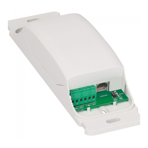
1. Configurator housing
2. BUS
3. LED intensity programming and adjustment pushbutton
LegendTechnical data
Power supply: BUS 18 – 27 Vdc
Max. consumption : 20 mA with configurator in INT= OFF,4
25 mA with configurator in INT= 0.2
35 mA with configurator in INT=1.3
Operating temperature: 0 – 40 °C
Depth: 18.3 mm
23
1
5739 12
5739 13
2
LG00047-c-UK
Configuration
Self-learning mode M=0
The configuration of the control can be made in two different modes
-
Physical configuration: by connecting the physical configurators to their housings
-
Virtual configuration: the control can be configured remotely, when no physical
configurators are available. (For the details refer to the Virtual Configuration).
Regardless of the mode, an A/PL address must always be assigned to the
control.
To operate the LED programming and brightness adjustment pushbutton, only use the screwdriver
provided.
Possible function M configurator value
This operating mode can be used to associate one individual control to any key of the device. It is possible to create, delete or
change each control. The display may be configured using any A/PL address already present in the system, or a unique address not
used by other devices.
0
Programming the Keys
To associate a different control to each key, proceed as follows
1) Press and release the key on the back, the LEDs come on in succession;
2) lightly touch the key to be programmed within 20 seconds: the LED will start
flashing, confirming that the programming mode is active
3) set the control to associate to the key, by operating the corresponding controls
and/or actuator. The LEDs start flashing in succession
4) it is now possible to repeat points 2 and 3 for all keys, including those that have
already been associated, if these need changing
5) press the pushbutton to exit programming, or wait 20 seconds to exit programming
automatically.
5739 12
5739 13
SET
A room
PL light point
M mode
SET LED display mode
SCS BUS SYSTEM
3
TECHNICAL SHEET
LG00047-c-UK
NOTE: To cancel the programming of all keys at the same time press and release the
key on the back. The LEDs will come on in succession. Press the pushbutton on the
back again, and hold it down for 10 seconds: all LEDs will flash for about 4 second to
confirm that all programming has been deleted.
Deleting the programming of the keys
1) Press and release the key on the back, the LEDs come on in succession;
2) Within 20 seconds press and hold down for 4 seconds the key for which
programming is to be cancelled; from now on, the key will no longer activate any
controls until reprogrammed;
3) the corresponding LED flashes for 4 seconds in alternative to the others, after
which it will be possible to repeat point 2, to delete other programming sequences;
4) quickly press the pushbutton, or wait 20 seconds to automatically exit delete
programming.
Non cyclic self-learning mode M=6
Scenario mode M=1 – 4
Possible function M configurator value
This mode is a variant of the self-learning mode (M=0), where, however, the keys never work cyclically. Therefore if, for example,
the ON of an actuator or dimmer is learnt, the couple of keys is configured automatically to switch on or increase the light intensity
level for the upper key, and switch off or decrease the level of intensity for the lower one. If, on the other hand, the single function
is learnt (e.g. recalling of a scenario), the other key of the pair remains without function, or retains the previous function. The display
may be configured using any A/PL address already present in the system, or a unique address not used by other devices.
6
Possible function M configurator value
This operating mode is useful if the system includes a scenario module, item 0035 51. The combination is ensured by assigning to both
items the same address, identified by A=0-9 and PL=1-9. The user may create, delete or change the scenarios saved in the scenario
module, and can recall them using the keys. With this procedure it is possible to save up to 16 scenarios using three 6-key devices.
1 – 4
The following table shows the correspondence between the number of the scenario saved in the scenario module, and the keys of the
control in the possible configurations: 3 module control (6 sensors)
Number of the key M=1 M=4 M=3
Key 1 scenario 1 scenario 7 scenario 13
Key 2 scenario 2 scenario 8 scenario 14
Key 3 scenario 3 scenario 9 scenario 15
Key 4 scenario 4 scenario 10 scenario 16
Key 5 scenario 5 scenario 11
Key 6 scenario 6 scenario 12
5739 12
5739 13
4
The combination of a scenario configured in the scenario programmer 035 65 and the corresponding control activation keys, is performed during the programming of the
scenario itself with the software supplied.
SPE=0 M=0/I; hi; hi M Swivelling modes
Possible function M configurator value
ON/OFF control: On control using the upper key, Off control using the lower key. For point-point controls, the ON/OFF functions
are performed by a quick pressure, while a longer pressure will be used for the adjustments; for the other controls only
the ON/OFF functions are performed
0/1
Control (UP-DOWN for rolling shutters): up-down control to end of stroke hi
Monostable control (UP-DOWN for rolling shutters): up-down control for the time the key is pressed hiM
These modes enable quick installation without the need for learning or scenario modules, allowing control of 2 consecutive light points or rolling shutters. The A PL address is the light
point or rolling shutter controlled by the first pair of keys. The subsequent pairs control the subsequent light points or rolling shutters. If the configurator Amb or Gr are connected to
A, in the same way the 2 pairs of keys control consecutive rooms or groups, starting from the one indicated by the configurator in PL.
The possible A and PL configurations are the following:
- Point-point: A=1 – 9 is the room, PL=1 – 9 is the light point.
- Room: A=AMB, PL=1 – 9 is the no. of the room.
- Group: A=GR, PL=1 – 9 is the no. of the group.
- General: A=GEN, PL=0 all pairs send the same general controls.
Cancel a scenario
1) The scenario module, item 0035 51 must be in configuration mode with
self-learning enabled;
2) Press and release the key on the back, the LEDs come on in succession;
3) Within 20 seconds press and hold down for 4 seconds the key of the scenario to be
cancelled;
4) The LEDs for the key of the device deleted flash for 4 seconds. Return to item 2 to
delete other programs.
5) Shortly press the relevant key or wait 20 seconds to exit the deleting mode;
NOTE:
the entire memory can only be reset from the scenario module: press and hold
down the "DEL" key for 10 seconds after enabling programming on the scenario module.
SPE=0 M=CEN Scenario programmer mode
Possible function M configurator value
Always assign to the control a specific A/PL address on the system (not to be used by any other device installed on the Bus), A=0
– 9, PL=0 – 9.
The A=0, PL=0 configuration cannot be accepted. This operating mode can only be used if the system includes a scenario
programmer (035 65).
CEN
DEL
035 51
Programming a scenario
1) The self-learning configuration of the scenario module, item 0035 51, must be
enabled (to do so press the self-learning pushbutton so that the corresponding
LED turns green; if the LED is red, self-learning is disabled);
2) Press and release the key on the back; the LEDs of the keys enabled and pro-
grammed for the scenario function will flash (1 sec. on and 1 sec. off);
3) Quickly press the key corresponding to the scenario to be programmed: the LED
will start flashing (upon receiving the update of the scenario module), confirming
that the programming mode is active.
4) Set the scenario using the corresponding controls and/or actuators.
5) Press the pushbutton to exit programming: the LEDs flash in succession, it is now
possible to repeat points 2, 3 and 4 for all scenarios, including those keys that
have already been associated, if they need changing.
6) Press the pushbutton on the back to exit programming, or wait 20 seconds to exit
programming automatically.
035 51
Scenario reset
pushbutton
Scenarios/learning reset
LED
Lock/unlock programming
pushbutton
Programming status LED
LG00047-c-UK
5739 12
5739 13
SCS BUS SYSTEM
5
TECHNICAL SHEET
Mode with SPE=1 - sound system mode -
This function is used to control the amplifiers and the sound system sources.
The functions performed are the following:
1) With a quick pressure of key 1, the following sequence is sent:
- OFF of the sources, only if M > 0
- ON of the M source (source 1 if M=0);
- ON of the amplifier.
2) With an extended pressure of key 1:
- for point-point controls, if the amplifier is already on, only the volume is adjusted
(VOL+); if the amplifier is off, the switch on sequence is sent first;
- for Room and General controls, only the volume is adjusted.
3) With an extended pressure of key 2, the volume is adjusted (VOL-). A quick pressure
sends the OFF control to the amplifier.
4) When key 3 is pressed the source is changed.
5) Key 4 is the control for the active source.
M=0 – 9 indicates the source to be activated before switching the amplifier on. If M=0,
source 1 is switched on without first switching OFF the sources (follow-me mode).
The possible A and PL configurations are the following:
- Audio point: A=0 – 9 is the amplifier room, PL=0 – 9 is the amplifier audio point.
- Room: A=AMB, PL= 0 – 9 is the room that the control is targeted at.
- General: A=GEN, PL= 0.
LG00047-c-UK
5739 12
5739 13
DEFAULT
0%
40%
25%
Once the device has been configured, it is possible to adjust the LED intensity by pressing
and holding down (t>2 s) the pushbutton on the back. The pushbutton operates on 3
intensity levels: from the default value (25%), the intensity changes every 2 seconds,
showing the levels that can be set, as per the following drawing. To select the desired
level simply release the pushbutton. Using the virtual configuration, the LED intensity
may be adjusted to 10 different levels.
If the user has decided that the keys should lit up when pressed (status return), the brightness level will depend on the adjustment of the LEDs as shown below:
LED intensity level status return intensity
25%
40%
0%
65%
70%
20%
LED intensity selection
6
Once the device has been installed, wait two minutes for the self-calibration procedure to be completed. During this period, controls may be automatically sent to the
system.
!
Configurator in the SET socket Behaviour
0•LED on even if the key has not been configured
•No status return
•Fade effect enabled
1•LED on even if the key has not been configured
•No status return
•Fade effect disabled
2•LED on only if the key has been configured (not configured -> LED off)
•No status return
•Fade effect enabled
3•LED on only if the key has been configured (not configured -> LED off)
•No status return
•Fade effect disabled
4•LED on even if the key has not been configured
•Status return enabled
•Fade effect enabled
5•LED on even if the key has not been configured
•Status return enabled
•Fade effect disabled
6•LED on only if the key has been configured (not configured -> LED off)
•Status return enabled
•Fade effect enabled
7•LED on only if the key has been configured (not configured -> LED off)
•Status return enabled
•Fade effect disabled
Use the SET configurator to select:
- if in the idle conditions the unused/not configured LEDs should stay off or on;
- if the LED should come on when the corresponding key is pressed (status return); for optimum status return effect it is recommended that the LED brightness level is kept low.
- if the fade effect on the lighting pushbuttons should be enabled or disabled.
LED display selection mode – SET position
LG00047-c-UK
5739 12
5739 13
This manual suits for next models

1

Other LEGRAND Controllers manuals

LEGRAND 0 663 40 User manual

LEGRAND

LEGRAND 0 663 40 User manual

LEGRAND 288 12 User manual

LEGRAND

LEGRAND 288 12 User manual

LEGRAND 672 40 User manual

LEGRAND

LEGRAND 672 40 User manual

LEGRAND Wattstopper DCLV2 User manual

LEGRAND

LEGRAND Wattstopper DCLV2 User manual

LEGRAND 0 883 27 User manual

LEGRAND

LEGRAND 0 883 27 User manual

LEGRAND EasyIP VADDIO PCC User manual

LEGRAND

LEGRAND EasyIP VADDIO PCC User manual

LEGRAND EasyIP VADDIO PCC User manual

LEGRAND

LEGRAND EasyIP VADDIO PCC User manual

LEGRAND Valena Next User manual

LEGRAND

LEGRAND Valena Next User manual

LEGRAND Adorne LC7001 User manual

LEGRAND

LEGRAND Adorne LC7001 User manual

LEGRAND PRO 21 7756 22 User manual

LEGRAND

LEGRAND PRO 21 7756 22 User manual

LEGRAND 0 677 886L User manual

LEGRAND

LEGRAND 0 677 886L User manual

LEGRAND Sagane 846 40 User manual

LEGRAND

LEGRAND Sagane 846 40 User manual

LEGRAND Adorne WNACB40 User manual

LEGRAND

LEGRAND Adorne WNACB40 User manual

LEGRAND radiant WNRCB40WH User manual

LEGRAND

LEGRAND radiant WNRCB40WH User manual

LEGRAND 0 663 35 User manual

LEGRAND

LEGRAND 0 663 35 User manual

LEGRAND Wattstopper DLM LMJA-8 Series User manual

LEGRAND

LEGRAND Wattstopper DLM LMJA-8 Series User manual

LEGRAND 0 648 84L User manual

LEGRAND

LEGRAND 0 648 84L User manual

LEGRAND BTICINO MYHOME F411U2 User manual

LEGRAND

LEGRAND BTICINO MYHOME F411U2 User manual

LEGRAND ALPTEC 5.2 User manual

LEGRAND

LEGRAND ALPTEC 5.2 User manual

LEGRAND 488 43 User manual

LEGRAND

LEGRAND 488 43 User manual

LEGRAND airQast User manual

LEGRAND

LEGRAND airQast User manual

LEGRAND Celiane 670 89 User manual

LEGRAND

LEGRAND Celiane 670 89 User manual

LEGRAND Arteor User manual

LEGRAND

LEGRAND Arteor User manual

LEGRAND radiant WZ3RCB40 User manual

LEGRAND

LEGRAND radiant WZ3RCB40 User manual

Popular Controllers manuals by other brands

Jung FST1240EB operating instructions

Jung

Jung FST1240EB operating instructions

Yoshitake OB-30 manual

Yoshitake

Yoshitake OB-30 manual

Texas Instruments TPS92512EVM-001 user guide

Texas Instruments

Texas Instruments TPS92512EVM-001 user guide

baxter DuploSpray MIS Instructions for use

baxter

baxter DuploSpray MIS Instructions for use

Honeywell MT8-024 Mounting instruction

Honeywell

Honeywell MT8-024 Mounting instruction

Trane TCONT 800 Series Integration guide

Trane

Trane TCONT 800 Series Integration guide

Phoenix Contact ILC 191 ME/AN Installing and operating information

Phoenix Contact

Phoenix Contact ILC 191 ME/AN Installing and operating information

Woodward 94911 product manual

Woodward

Woodward 94911 product manual

Robotis Dynamixel DX-116 user manual

Robotis

Robotis Dynamixel DX-116 user manual

Rotenso CONTROL Series Installation and user manual

Rotenso

Rotenso CONTROL Series Installation and user manual

National Instruments PXI-7358 Getting started

National Instruments

National Instruments PXI-7358 Getting started

SOMFY animeo IB + installation guide

SOMFY

SOMFY animeo IB + installation guide

Koer C35-FC Technical manual

Koer

Koer C35-FC Technical manual

iLive IVR77 user guide

iLive

iLive IVR77 user guide

Lawler 801-GPM Installation & maintenance manual

Lawler

Lawler 801-GPM Installation & maintenance manual

Xylem McDonnell & Miller 150S Series instruction manual

Xylem

Xylem McDonnell & Miller 150S Series instruction manual

Ametek dunkermotoren BGE 6010 A Operation manual

Ametek

Ametek dunkermotoren BGE 6010 A Operation manual

Danfoss VLT HVAC Basic Drive FC 101 quick guide

Danfoss

Danfoss VLT HVAC Basic Drive FC 101 quick guide

manuals.online logo
manuals.online logoBrands
  • About & Mission
  • Contact us
  • Privacy Policy
  • Terms and Conditions

Copyright 2025 Manuals.Online. All Rights Reserved.