A
template
is
jncluded
in
the installation kit. Place the 'Drilling Template
for
MK8
&
MK9'
where you want your
unit
installed. Be sure that you have access
to back side
for
tightening the nuts.
Recommended
tools
for
installation.
Toots:
*
Adjustable spanner
*
Drill
13rnm
*
Drill
9mm
*
Drill
7mm
*
Electric power
drill
*
Hand file
Use:
To
tighten the nuts.
Hole
for
antenna mounting.
Holes for D
-
SUB connector.
Holes for mounting stays.
To
smooth the hole for the
5
-
SUB
connector
The
navigator
is
designed for
12V
or
24V
battery supply,
but
the
unit
will
work
with
any
DC
voltage from
9.6V
to
32V.
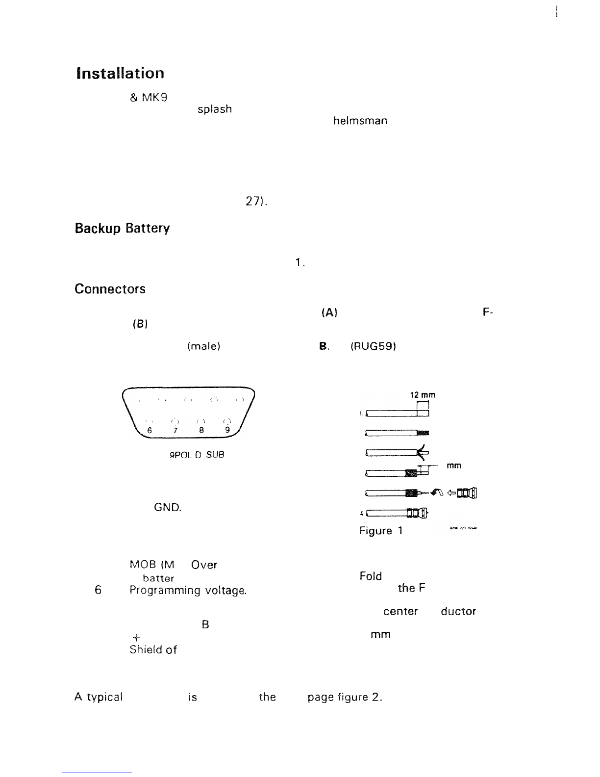
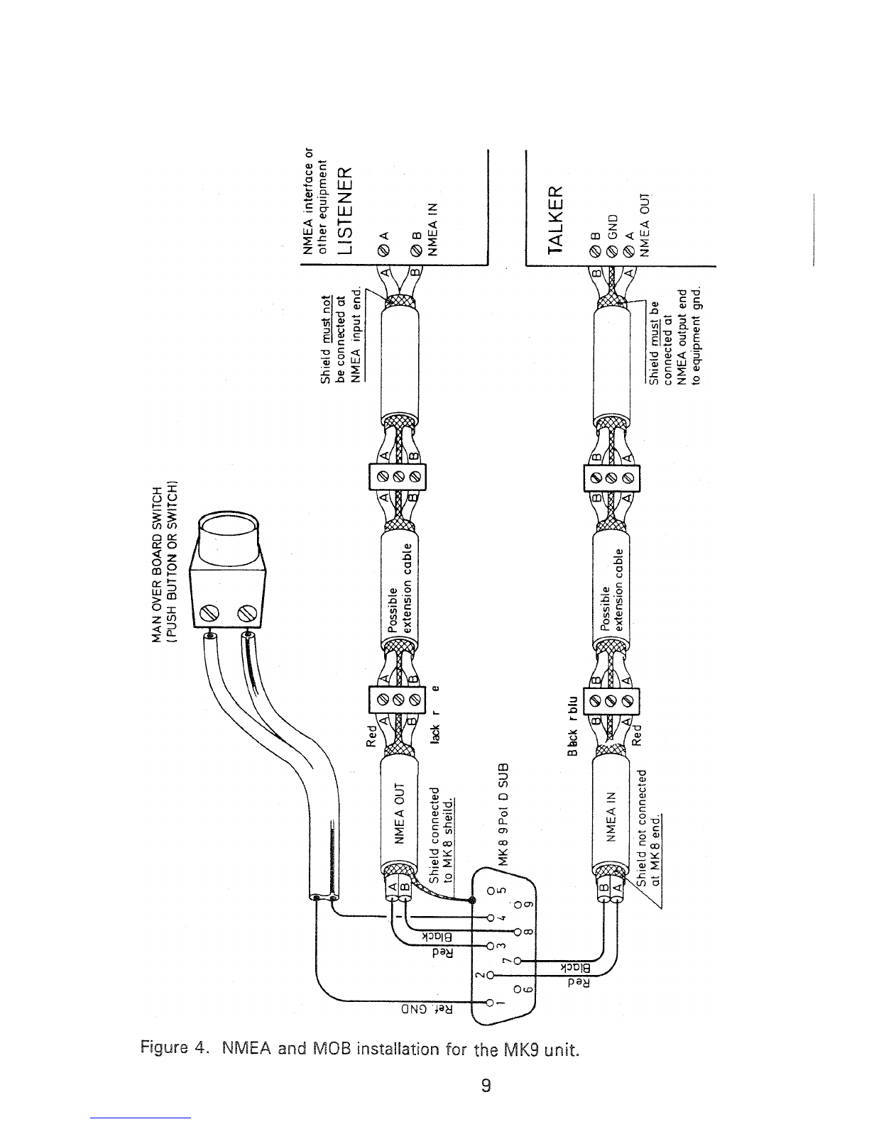
The installation kit includes a
9
socket
D
-
SUB
connector mounted
with
all the
necessary cabling. The Power Cable is a joint
RED
and BLACK pair:
BLACK wire (D
-
SUB socket
51
should be connected to the minus
pole
of
the battery.
RE5
wire (D
-
SUB socket
9)
should be connected to the plus pole of the
battery.
Please be sure to have a fuse
in
the circuit
-
not to protect the navigator
-
but
to protect
the
cabling. (Short
-
circuiting
a
cable with direct connection
to
a
battery
will
make severe damage).
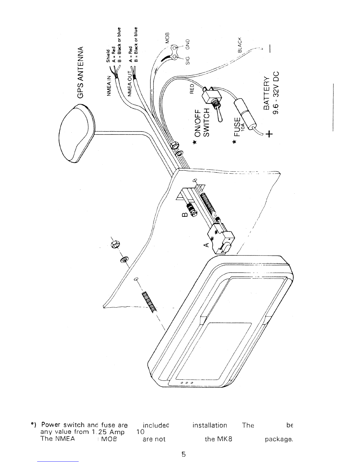
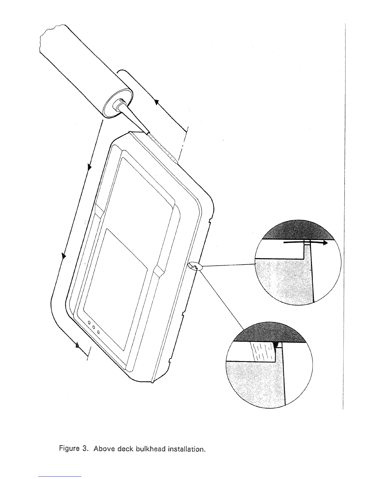
A
typical installation
is
shown
in
figure
2
page
5.
The electronics
of
the navigator
is
isolated
from
the external power supply.
It
is
recommended
to
ground the shield
of
the navigator
to
avoid static charge
built
up.
This can
be
done
in
one
of
two ways:
1)Connect
the
D
-
SUB
'GND'
pin
1
of
the
navigator
to
boat's seawater
ground.
2)Connect the antenna mounting
(nut
etc.) to the boat's seawater
ground.
'Seawater ground' is any structure
in
connection
with
the sea below the water
-
line. The connection could be through
a
10
KOhm resistor.
Antenna mounting
and
navigator shield
is
electrically connected through
the
screen
of
the antenna cable.
To
avoid current loops do only
use
one
of
the two
grounding methods.
If
the antenna
is
mounted on the push
pit
or
similar metal
structure
we
recommend using that
part
for
grounding of the navigator
(possi
-
bly
by connecting
it
to
boat's
seawater ground).
c