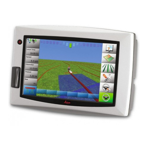
Leica mojo 3D User manual

Leica
User Manual
mojo3D
Version 3.0
English

2
Leica mojo3D, Introduction
Introduction
Purchase Congratulations on the purchase of a Leica mojo3D system.
This manual contains important safety directions as well as instructions for setting
up the product and operating it. Refer to "14 Safety Directions" for further informa-
tion. Read carefully through this User Manual before you switch on the product.
To ensure safety when using the system, please also observe the directions and
instructions contained in the User Manual and Safety Handbook issued by the:
• Agricultural machinery manufacturer.
Product identifica-
tion
The type and serial number of your product are indicated on the type plate. Enter the
type and serial number in your manual and always refer to this information when you
need to contact your agency or Leica Geosystems authorised service workshop.
Symbols used in
this manual
The symbols used in this manual have the following meanings.
Type: _______________
Serial No.: _______________
Type Description
Danger Indicates an imminently hazardous situation which, if not
avoided, will result in death or serious personal injury.

Leica mojo3D, Introduction 3
Trademarks All other trademarks are the property of their respective owners.
Available
documentation
Warning Indicates a potentially hazardous situation or an unintended use
which, if not avoided, could result in death or serious personal
injury.
Caution Indicates a potentially hazardous situation or an unintended use
which, if not avoided, may result in minor or moderate personal
injury, appreciable material, financial and environmental damage,
or all of these.
Important paragraphs which must be adhered to in practice as
they enable the product to be used in a technically correct and
efficient manner.
Type Description
Name of documentation Description
mojo3D/ mojoXact
User Manual
All instructions required in order to operate the
product to a basic level are contained in this User
Manual. Provides an overview of the system together
with technical data and safety directions.

4
Leica mojo3D, Table of Contents
Table of Contents
In this manual Chapter Page
1 System Overview 12
1.1 General mojo3D System Information 12
1.2 Components of the mojo3D System 13
1.3 Features and Specifications 15
1.3.1 mojo3D Hardware 15
1.3.2 mojo3D Software 17
1.3.3 mojo3D Positioning 17
1.3.4 mojo3D Guidance 18
1.3.5 mojo3D Section Control and Mapping 18
2 System Installation 20
2.1 Before Installation 20
2.2 mojo3D Installation 22
2.3 Antenna Installation 25
2.4 SIM Card Installation 29
3 Running the mojo3D for the First Time 32
3.1 Starting Up 32
3.2 Setting the Screen Calibration 34

Leica mojo3D, Table of Contents 5
3.3 Initial Setup Wizard 35
3.4 Menu Buttons at Right of Screen 49
3.5 Menu Buttons at Left of Screen 51
3.6 Specifying Data for Display 52
3.7 Zoom Buttons 54
3.8 View Modes 55
3.9 Error Notifications 56
3.10 Running the Setup Wizard at any Time 60
3.11 Changing System Settings 61
3.12 Vehicle Setup 62
3.13 Attached Device Selection 63
3.14 NMEA Configuration 65
3.15 Feature Unlock 66
4 Setting Guidance Types 68
4.1 AB Parallel Guidance 68
4.2 A+ Heading Guidance 70
4.3 Fixed Contour Guidance 72
4.4 Pivot Guidance 74
4.5 Ultimate Curve Guidance 76
4.6 Stop Guidance 79
4.7 Guidance Management 80
4.7.1 Saving a Wayline 80
4.7.2 Changing the Name of a Wayline 81

6
Leica mojo3D, Table of Contents
4.7.3 Deleting an Individual Wayline 82
4.7.4 Deleting All Waylines 83
4.7.5 Exporting Waylines 85
4.7.6 Importing Waylines 90
4.7.7 Replay Guidance 97
4.8 Field Offset 99
4.9 Nudge 101
5 Auto-Steer 102
5.1 Engage Auto-Steer 102
5.2 Tuning Auto-Steer Performance 106
5.2.1 Tuning Procedure 106
5.2.2 Sensitivity 109
5.2.3 Aggressiveness 110
5.2.4 Overshoot 111
5.2.5 Speed Adjust 112
5.2.6 Tuning Tips 113
5.2.7 Swap Left and Right Steering Control 115
5.3 Stationary Engage and Reverse Steering 117
5.4 Testing Auto-Steer 123
6 Treatments 128
6.1 Starting a New Treatment 129
6.2 Load a Stored Treatment 130

Leica mojo3D, Table of Contents 7
6.3 Changing a Treatment Name 131
6.4 Creating a PDF Report of a Treatment 132
6.5 Deleting a Treatment 134
6.6 Exporting Treatment Data 136
6.7 Importing Treatment Data 142
7 Automatic Section Control 146
7.1 Section Control Latency 147
7.1.1 Calibrating the Section Control Latency Value 148
7.1.2 Troubleshooting Latency Problems 150
7.2 Setting the Overlap Limit 153
7.3 Setting the Low-Speed Shutoff 155
7.4 Section Override Control 157
8 Field Boundary 158
8.1 Create a New Field Boundary 158
8.2 Load a Stored Field Boundary 160
8.3 Changing a Field Boundary Name 161
8.4 Deleting a Field Boundary 162
8.5 Exporting Field Boundary Data 163
8.6 Importing Field Boundary Data 169
9 Vehicles and Implements 178
9.1 Saving a Vehicle or Implement Configuration 179

8
Leica mojo3D, Table of Contents
9.2 Load a Vehicle or Implement Configuration 181
9.3 Renaming a Vehicle or Implement Configuration 183
9.4 Deleting Vehicle or Implement Configurations 186
9.5 Exporting Vehicle or Implement Configurations 191
9.6 Importing Vehicle and Implement Configurations 195
10 Correction Sources 202
10.1 Network DGPS 203
10.2 SBAS 209
10.3 GL1DETM 211
10.4 Network RTK 215
10.5 RTK Base Station (Internal Radio) 221
11 NMEA Output 226
11.1 Configuring NMEA Output 227
11.2 Logging NMEA Data to USB 230
11.3 NMEA Sentences Available 232
12 Virtual Wrench™ Remote Service 234
12.1 Virtual Wrench™ 234
12.2 Making a Service Request 235
12.3 Upgrading Software from Virtual Wrench™ 236
12.4 Upgrading Software via USB Flash Drive 238
12.5 Restoring Previous Software Version 240

Leica mojo3D, Table of Contents 9
12.6 Backing Up Current Software 242
12.7 Serial Numbers and Other System Information 244
13 Care and Transport 246
13.1 Transport 246
13.2 Storage 246
13.3 Cleaning and Drying 247
14 Safety Directions 248
14.1 General Introduction 248
14.2 Intended Use 249
14.3 Limits of Use 251
14.4 Responsibilities 251
14.5 Hazards of Use 253
14.6 Electromagnetic Compatibility (EMC) 259
14.7 FCC Statement, Applicable in U.S. 262
14.8 ICES-003 Statement, Applicable in Canada 263
14.9 Labelling 264
15 Technical Data 268
15.1 mojo3D Display Technical Data 268
15.2 mojo3D GPS Receiver Technical Data 271
15.3 Wireless Modules Technical Data 273
15.3.1 HSDPA Wireless Module Technical Data 273

10
Leica mojo3D, Table of Contents
15.3.2 CDMA Wireless Module Technical Data 275
15.4 Antennas Technical Data 277
15.4.1 GPS Patch Antenna Technical Data 277
15.4.2 Cellular Antenna Technical Data 280
15.4.3 mojoXact and mojoXact Plus Red Antenna Technical Data 282
15.4.4 mojoXact Black GeoPRO Antenna Technical Data 286
15.5 mojoXact Technical Data 289
15.6 mojoXact GPS Receiver Technical Data 292
15.7 mojoXact Plus Technical Data 294
15.8 mojoXact Plus GPS Receiver Technical Data 297
15.9 Conformity to National Regulations 299
15.9.1 mojo3D 299
15.9.2 mojoXact 301
15.9.3 mojoXact Plus 303
16 International Limited Warranty, Software License Agreement 306
Appendix A mojo3D Enhancements 308
A.1 mojo3D with Single Section Control 308
A.2 mojo3D with Multi Section Control Kit 313
A.3 mojo3D with GeoPRO Antenna 320
A.4 mojo3D with mojoXact Kit 325
A.4.1 Leica mojoXact 326
A.4.2 Installation 327

Leica mojo3D, Table of Contents 11
A.4.3 Antenna Installation 329
A.4.4 Leica mojoXact Installation 334
A.5 Redeeming a System Option Voucher 364
Appendix B Formatting USB Flash Drives 366
Appendix C GNU General Public License 372
Appendix D Glossary of Terms 374

12
Leica mojo3D, System Overview
1 System Overview
The images in this manual are for reference purposes only. Individual screens and
icons may differ from the actual items.
1.1 General mojo3D System Information
General informa-
tion
• Leica Geosystems' mojo3D is a GPS-based agricultural guidance system that
provides visual guidance and mapping with optional auto steering and section
control.
• Beyond its capabilities of visual or auto steer guidance and section control the
mojo3D also provides remote service and diagnostics and remote upgrades via
Virtual Wrench, thus reducing costly on-site service calls.

Leica mojo3D, System Overview 13
1.2 Components of the mojo3D System
mojo3D compo-
nents
a) RAM mount - ball
b) RAM mount - arm
c) mojo3D display
d) Glass-mount cell modem antenna
e) Magnetic-mount GPS antenna
f) Standard power cable
g) Product documentation
a
d
e
f
g
mojo3D_001
b
c

14
Leica mojo3D, System Overview
mojo3D accessory
options
• Port expansion cable
• Multi-Section control kit
• Electric auto-steer kit
• mojoRTK console
• mojoRTK external control cable
• mojoXact
• GeoPRO antenna
Refer to "Appendix A mojo3D Enhancements" for more information about the acces-
sory options, their installation and use.

Leica mojo3D, System Overview 15
1.3 Features and Specifications
1.3.1 mojo3D Hardware
mojo3D hardware
features
• Simple installation, with RAM mount and colour-coded quick-install antennas
• Integrated L1 GPS receiver
• Integrated cell modem, CDMA or HSDPA depending on region ordered
• 12 volt operation
• Internal storage for waylines, worked areas, and settings
a) USB interface for data transfer
b) Power button
c) 7" colour touch screen
d) Port expansion connector
e) Connector for GPS antenna, blue
f) Connector for cell modem antenna,
purple
g) Power connector
h) Cover for SIM card slot
i) RAM mount - ball
a cb
g
de f
h i
mojo3D_002

16
Leica mojo3D, System Overview
Caution Operation by touch screen:
The mojo3D is designed to be used by a finger tapping the display screen. It may
affect warranty if operated with a hard object i.e. stylus or pen.

Leica mojo3D, System Overview 17
1.3.2 mojo3D Software
mojo3D software
features
• Intuitive software that allows for easy setup and use
• On screen field guidance and coverage mapping
• Auto-steer compatible
• Multi & single automatic section control
• Upgrade, backup, and rollback of software through USB
• Virtual Wrench™, which provides remote support and over-the-air software
upgrades
1.3.3 mojo3D Positioning
mojo3D posi-
tioning features
• GPS algorithms are tuned for the agricultural environment.
• Multi-link implement modelling, to provide high accuracy recording of worked
areas.
• Optional NMEA (NMEA 0183) output for auxiliary devices that require GPS data.
• Optional Radar-out signal for auxiliary devices that require a radar speed signal.
• Leica Twist compatible for terrain compensated electric auto steer.
• Leica mojoRTK Console or mojoXact compatible for base station RTK, Network
RTK, and Dual Frequency GL1DE™.

18
Leica mojo3D, System Overview
1.3.4 mojo3D Guidance
mojo3D guidance
features
• Multiple guidance patterns for visual guidance, including AB Parallel, A+ Heading,
Fixed Contour, Pivot and Ultimate Curve.
• View in 3D perspective, with heads-up, chase, top-down, and north-up modes.
• On-screen lightbar with heading assist operation.
• Electric auto-steer capable, with Electric Steer Kit.
• Hydraulic auto-steer capable, with Leica mojoRTK Console or Leica mojoXact.
1.3.5 mojo3D Section Control and Mapping
mojo3D section
control and
mapping features
• Single-section control using port expansion cable
• Multi-section control capability with Multi-Section Kit
• Direct Section Control capability with Direct Section Kit
• Recording of worked area, with the ability to export PDF reports to a USB Flash
Drive for archiving

Leica mojo3D, System Overview 19

20
Leica mojo3D, System Installation
2 System Installation
2.1 Before Installation
General installa-
tion information The installer must read and study this user manual, including the safety
directions. The installer must be able to use the system in accordance with
the user manual. Leica Geosystems recommends that installation of the
mojo3D equipment be performed by a qualified technician, because instal-
lation requires making electrical connections.
• The following instructions are to be used as a general guide during the installa-
tion of the mojo3D.
• The system will not operate at peak performance if steering joints and linkage
assemblies are not within the manufacturer's specifications. Check for worn
steering components by turning the steering wheel. As the steering wheel is
turned, the wheels should begin to move. If results are undesirable, please
consult your vehicle manufacturers’ maintenance manual.
• Install the system in a clean and dry workshop environment. Failure to do so may
cause the system to short or promote product malfunction. Any moisture on
the roof of the vehicle will also prevent the antenna mounting tape from
sticking properly.
• Route and secure all cables and wiring to ensure that they do not chafe or rub,
causing premature failure.
Table of contents
Other Leica GPS manuals

Leica
Leica GS20 User manual

Leica
Leica T-Scan 5 User manual

Leica
Leica GPS1200+ Product manual

Leica
Leica Digilux 2 User manual

Leica
Leica MK8 User manual

Leica
Leica GPS1200+ Instructions for use

Leica
Leica T-Scan5 User manual

Leica
Leica mojo3D User manual

Leica
Leica mojo3D User manual

Leica
Leica RX1250 SmartRover User manual

Leica
Leica GG02 User manual

Leica
Leica GPS1200 Series User manual

Leica
Leica MX400 User manual

Leica
Leica MojoMINI User manual

Leica
Leica INEX 1-1296 User manual

Leica
Leica MojoMINI User manual

Leica
Leica apMK12 User manual

Leica
Leica iNEX User manual

Leica
Leica DistoX2 User manual

Leica
Leica GS09 User manual