Leica GPS1200+ Instructions for use

Leica GPS1200+
Applications
Field Manual
Version 7.1
English

2GPS1200+ Introduction
Introduction
Purchase Congratulations on the purchase of a GPS1200+ Series instrument.
)To use the product in a permitted manner, please refer to the detailed safety direc-
tions in the User Manual.
Product
identification
The type and the serial number of your product are indicated on the type plate.
Enter the type and serial number in your manual and always refer to this information
when you need to contact your agency or Leica Geosystems authorized service
workshop.
Symbols The symbols used in this manual have the following meanings:
Trademarks • Windows and Windows CE are a registered trademark of Microsoft Corporation
• CompactFlash and CF are trademarks of SanDisk Corporation
• Bluetooth is a registered trademark of Bluetooth SIG, Inc
All other trademarks are the property of their respective owners.
Validity of this
manual
• This manual applies to all GPS1200+ instruments. Differences between the
various models are marked and described.
• The RX1200 is available as RX1210 or with touch screen functionality as
RX1210T, RX1250X, RX1250Xc, RX1250T or RX1250Tc. The name RX1210 is
used throughout the manual and may also represent the touch screen models.
Only use the supplied stylus on the screens of the touch screen models.
• This manual covers standard real-time surveying applications. Refer to the
GPS1200+ Technical Reference Manual for information about other function-
ality available.
Available
documentation
Type: _____________________
Serial No.: _____________________
Type Description
)Important paragraphs which must be adhered to in practice as
they enable the product to be used in a technically correct and
efficient manner.
Name Description Format
User Manual All instructions required in order to
operate the product to a basic level are
contained in the User Manual. Provides
an overview of the product together with
technical data and safety directions.
xx

Introduction GPS1200+ 3
Refer to the following resources for all GPS1200+ documentation and soft-
ware:
• the SmartWorx DVD
• http://www.leica-geosystems.com/downloads
Name Description Format
System Field Manual Describes the general working of the
product in standard use. Intended as a
quick reference field guide.
-x
Application Programs
Field Manual
Describes specific onboard application
programs in standard use. Intended as a
quick reference field guide. The Road-
Runner application program is described
in a separate manual.
xx
Technical Reference
Manual
Overall comprehensive guide to the
product and program functions. Included
are detailed descriptions of special soft-
ware/hardware settings and soft-
ware/hardware functions intended for
technical specialists.
-x

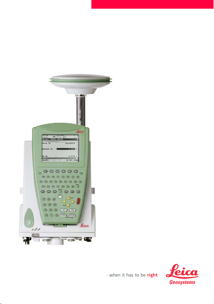
4GPS1200+ Table of Contents
Table of Contents
In this manual Chapter Page
1 Application Programs - Getting Started 7
1.1 Starting an Application Program 7
1.2 Configuration of a Logfile 10
2 COGO 11
2.1 Overview 11
2.2 Accessing COGO 12
2.3 Configuring COGO 13
2.4 COGO Calculation - Inverse Method 15
2.4.1 Inverse Point - Point 16
2.4.2 Inverse Point - Line 17
2.4.3 Inverse Point - Arc 20
2.4.4 Inverse Point - Current Position 23
2.5 COGO Calculation - Traverse Method 25
2.6 COGO Calculation - Intersections Method 29
2.7 COGO Calculation - Line/Arc Calculations Method 33
2.8 COGO Calculation - Shift, Rotate & Scale (Manual) Method 39
2.9 COGO Calculation - Shift, Rotate & Scale (Match Pts) Method 44
2.10 COGO Calculation - Area Division 46
3 Determine Coordinate System - General 53
3.1 Overview 53
3.2 Configuring Determine Coordinate System 55
3.2.1 Configuring Determine Coordinate System - Normal 55
3.2.2 Configuring Determine Coordinate System -
One Point Localisation 57
4 Determine Coordinate System - Normal 59
4.1 Determining a New/Updating a Coordinate System 59
4.2 Selecting/Editing a Pair of Matching Points 64
4.3 Transformation Results 65
5 Determine Coordinate System - One Point Localisation 67
5.1 Accessing Determine Coordinate System -
One Point Localisation 67
5.2 Determine Coordinate System -
Onestep/Twostep Transformation 68
5.2.1 Determining a New Coordinate System 68
5.2.2 Computing the Grid Scale Factor for
Twostep Transformations 74
5.2.3 Computing the Height Scale Factor for
Twostep Transformations 75
5.3 Determine Coordinate System - Classic 3D Transformation 76
5.4 Computing Required Azimuth 77
6 Reference Line 79
6.1 Overview 79
6.2 Configuring Reference Line 81
6.3 Managing Reference Lines/Arcs 84
6.3.1 Overview 84

Table of Contents GPS1200+ 5
6.3.2 Manually Entering a Reference Line/Arc 85
6.3.3 Selecting a Reference Line/Arc from the Job 88
6.3.4 Defining Reference Line/Arc Offsets 91
6.3.5 Defining Reference Line/Arc Slope 92
6.4 Measuring to a Reference Line/Arc 94
6.5 Staking to a Reference Line/Arc 99
6.6 Gridstaking to a Reference Line/Arc 102
6.7 Staking to a Polyline 104
6.7.1 Overview 104
6.7.2 Accessing Staking to Polylines & Choosing a Polyline 105
6.7.3 Stake Parameters 106
6.7.4 Staking Operation 108
6.7.5 Results of Stakeout 111
7 Reference Plane 113
7.1 Overview 113
7.2 Configuring Reference Plane 115
7.3 Managing Reference Planes 116
7.4 Measuring Points to a Reference Plane 120
8 Stakeout 123
8.1 Overview 123
8.2 Configuring Stakeout 124
8.3 Staking Out 128
8.4 Stakeout Difference Limit Exceeded 131
9 Survey - General 133
9.1 Pre-Survey Preparations 133
9.2 Static Operations 135
9.3 Post-Processed Kinematic Operations 138
9.4 Real-Time Reference Operations 139
9.5 Real-Time Rover Operations 141
10 Survey - Auto Points 143
10.1 Overview 143
10.2 Configuring Auto Points 144
10.3 Auto Points for Post-Processed Kinematic and
Real-Time Rover Operations 148
10.4 Offset Points of Auto Points 151
10.4.1 Overview 151
10.4.2 Configuring Offset Points 152
11 Survey - Hidden Points 153
11.1 Overview 153
11.2 Measuring Hidden Points 154
11.3 Hidden Point Measurement Including Heights 161
12 Survey Cross Section 165
12.1 Overview 165
12.2 Configuring Survey Cross Section 166
12.3 Surveying Cross Sections 168
12.4 Cross Section Templates 170
12.4.1 Accessing Cross Section Template Management 170
12.4.2 Creating/Editing a Cross Section Template 171

Application Programs - Getting Started GPS1200+ 7
1 Application Programs - Getting Started
1.1 Starting an Application Program
Access an applica-
tion program step-
by-step
XX Begin SURVEY Survey Begin is shown as an example. Additional fields are available for
particular application programs. The first screen of Wake-Up Sessions differs from
XX Begin and is explained in the chapter on Wake-Up Sessions.
Description of fields
Step Description
1. Press PROG. The PROG key opens the application programs menu
GPS1200+ Programs.
2. GPS1200+ Programs
Select an option in the menu.
3. CONT (F1) to access XX Begin.
)Some application programs are protected. They are activated through a
specific licence key. This can either be typed in in Main Menu:
Tools...\Licence Keys or the first time the application program is started.
)Four application programs can be open at one time. XX Begin is shown
for the application program opened first, but not for the following applica-
tion programs.
CONT (F1)
To accept changes and access the
subsequent screen.
CONF (F2)
To configure the application program.
CSYS (F6)
To select a different coordinate
system. Not available for <Use Auto
CrdSys: Yes> configured in CONG-
FIGURE Additional Rover
Settings.
Field Option Description
<Control
Job:>
Choicelist Available for Reference Line. The original points
to be staked and the reference lines/arcs are
stored in this job.
<Stakeout
Job:>
Choicelist Available for Stakeout. The job containing the
points to be staked.
<Job:> Choicelist The active job.
For Stakeout and Reference Line: Points which
are occupied after staking out are stored in this
job. The original points to be staked are not
copied to this job.

8GPS1200+ Application Programs - Getting Started
Description of fields for Determine Coordinate System
Next step
<Coord
System:>
Output The coordinate system currently attached to the
selected <Job:>.
<Codelist:> Choicelist No codes are stored in the selected <Job:>. All
codelists from Main Menu:
Manage...\Codelists can be selected.
Output Codes have already been stored in the selected
<Job.>.
<DTM Job:> Choicelist Available for Stakeout if <Use DTM: DTM only>
and <Use DTM: DTM & Stake Job> in
STAKEOUT Configuration, Heights page.
Available for Reference Line if <Heights: Use
DTM Model> in REFLINE Configuration,
Heights page.
To select a DTM to be staked and to select the
active DTM layer to be used. Heights are then
staked out relative to the selected DTM.
<Config
Set:>
Choicelist The active configuration set.
<Antenna:> Choicelist The antenna currently defined to be used in the
selected configuration set.
Field Option Description
<Name:> User input A unique name for the coordinate system. The
name may be up to 16 characters in length and
may include spaces. Input is mandatory.
)Entering the name of an existing coor-
dinate system will allow that system to
be updated.
<WGS84 Pts
Job:>
Choicelist The job from which the points with WGS84 coor-
dinates will be taken.
<Local Pts
Job:>
Choicelist The job from which the points with local coordi-
nates will be taken.
<Method:> Choicelist Method used to determine the coordinate
system.
IF the application
program
THEN
is to be accessed CONT (F1) accepts the changes and starts the application
program. Refer to the relevant chapters.
Field Option Description

Application Programs - Getting Started GPS1200+ 9
is to be configured CONF (F2). Refer to the relevant chapters.
IF the application
program
THEN

10 GPS1200+ Application Programs - Getting Started
1.2 Configuration of a Logfile
Description A logfile is a summary of the calculations done while using an application program.
The logfile is written to the \DATA directory of the CompactFlash card or internal
memory if fitted. The creation of a logfile can be activated while configuring an appli-
cation program.
Access step-by-
step
XX
Configuration,
Logfile page
Description of fields
Next step
PAGE (F6) changes to the first page on this screen.
Step Description
1. Refer to "1.1 Starting an Application Program" to access XX Begin.
2. CONF (F2) to access XX Configuration.
3. PAGE (F6) until the Logfile page is active.
Field Option Description
<Write
Logfile:>
Yes or No To generate a logfile when the application
program is exited.
<File Name:> Choicelist Available for <Write Logfile: Yes>. The name
of the file to which the data should be written.
<Format
File:>
Choicelist Available for <Write Logfile: Yes>. A format file
defines which and how data is written to a
logfile. Format files are created using LGO.

COGO GPS1200+ 11
2COGO
2.1 Overview
Description COGO is an application program to perform coordinate geometry calculations such
as
The calculations can be made from
• existing point data in the job, known distances or known azimuths.
• manually occupied points.
• entered coordinates.
)Changing coordinates of a point which has been previously used in COGO does not
result in the point being recomputed.
COGO calculation
methods
The COGO calculation methods are:
Distances and
azimuths
• coordinates of points. • distances between points.
• bearings between points.
• Inverse. • Arc calculations.
• Traverse. • Shift, Rotate & Scale (Manual)
• Intersections. • Shift, Rotate & Scale (Match Pts)
• Line calculations. • Area Division
Type of distances: The choices are
• Ground
•Grid
• Ellipsoidal
Type of azimuths: The azimuths are grid azimuths relative to the local grid.

12 GPS1200+ COGO
2.2 Accessing COGO
Access step-by-
step Step Description
1. Refer to "1.1 Starting an Application Program" to access COGO COGO
Menu.
2. COGO COGO Menu
The COGO menu lists all COGO calculation methods and the option to
end COGO.
Highlight the COGO calculation method to be started.
3. CONT (F1) to access the screen for the COGO calculation method.
)The screens for each COGO calculation method can be accessed directly
by pressing a configured hot key or USER. The currently active configura-
tion set and job are used.

COGO GPS1200+ 13
2.3 Configuring COGO
Access
COGO
Configuration,
Parameters page
The explanations for the softkeys given below are valid for all pages, unless other-
wise stated.
Description of fields
Step Description
1. Press PROG.
2. Highlight COGO.
3. CONT (F1)
4. In COGO COGO Begin press CONF (F2) to access COGO Configura-
tion.
CONT (F1)
To accept changes and return to the
screen from where this screen was
accessed.
SHIFT ABOUT (F5)
To display information about the
program name, the version number,
the date of the version, the copyright
and the article number.
Field Option Description
<Distance
Type:>
Grid, Ground or
Ellipsoid
The type of distances and offsets to be accepted
as input or shown as output, and used in the
calculation.
<Use
Offsets:>
Yes or No Activates the use of offsets in the COGO calcu-
lations. Input fields for the offsets are available
in COGO XX.
<Store Pts
As:>
MEAS or CTRL Defines the point class of COGO calculated and
stored points as MEAS or CTRL triplets.
<Est Pos
Qlty:>
User input The estimated value for the position quality
assigned to all calculated COGO points which is
used for the averaging calculation.
TPS12_170
P1
a
d1
d2
d3
P2
a Ellipsoid
Known
P1 First known point
P2 Second known point
Unknown
d1 Ground distance
d2 Ellipsoid distance
d3 Grid distance

14 GPS1200+ COGO
Next step
PAGE (F6) changes to the Residuals page.
COGO
Configuration,
Residuals page
This page applies to COGO Shift, Rotate & Scale (Match Pts).
Description of fields
Next step
PAGE (F6) changes to the Logfile page. Refer to "1.2 Configuration of a Logfile".
)<Azimuth:> is used throughout this chapter. This should always be considered to
also mean <Bearing:>.
<Est Ht
Qlty:>
User input The estimated value for the height quality
assigned to all calculated heights which is used
for the averaging calculation.
<TPS Obs -
TPS Obs
Intersection>
Output text COGO method for which only the following
configuration setting is valid.
<Compute
Ht:>
Using Average,
Use Upper
Height or Use
Lower Height
Defines the height being used within TPS Obs -
TPS Obs Intersection.
Field Option Description
<Easting:>,
<Northing:>
or <Height:>
User input The limit above which Easting/Northing/Height
residuals will be flagged as possible outliers.
<Residual
Distbtn:>
The method by which the residuals of the control
points will be distributed throughout the transfor-
mation area.
None No distribution is made. Residuals remain with
their associated points.
1/DistanceXX Distributes the residuals according to the
distance between each control point and the
newly transformed point.
Multiquadratic Distributes the residuals using a multiquadratic
interpolation approach.

COGO GPS1200+ 15
2.4 COGO Calculation - Inverse Method
Diagram Point - Point
Point - Line
Point - Arc
Point - Current Position
Access Refer to "2.2 Accessing COGO" to access COGO Inverse.
Known
P0 First known point
P1 Second known point
Unknown
αDirection from P0 to P1
d1 Slope distance between P0 and P1
d2 Horizontal distance between P0 and P1
d3 Height difference between P0 and P1
Known
P0 Start point
P1 End point
P2 Offset point
Unknown
P3 Base point
d1 Offset-XX
d2 ΔLine-XX
Known
P0 Start point
P1 End point
P2 Offset point
Unknown
P3 Base point
d1 Offset-XX
d2 ΔArcDist-XX
Known
P0 Current position
P1 Second known point
Unknown
αDirection from P0 to P1
d1 Slope distance between P0 and P1
d2 Horizontal distance between P0 and P1
d3 Height difference between P0 and P1
GPS12_062
P0
P1
d
GPS12_119
P0
P1
P2
d2 d1
P3
GPS12_121
P0
P1
P3
d2
d1
P2
GPS12_062
P0
P1
d

16 GPS1200+ COGO
2.4.1 Inverse Point - Point
COGO
Inverse Input,
Inverse page
The COGO calculation results are displayed on the same page.
----- is displayed for unavailable information, for example if a position only point is
used, <ΔHeight:> cannot be calculated.
Description of fields
Next step
STORE (F1)
To store the result.
SURVY (F5)
To manually occupy a point for the
COGO calculation. Available if
<From:> or <To:> is highlighted.
SHIFT CONF (F2)
To configure the COGO application
program.
SHIFT QUIT (F6)
To not store the calculated results
and exits COGO calculation.
Field Option Description
<From:> or
<To:>
Choicelist The point ID of the known points.
)To type in coordinates for a known point
open the choicelist when <From:> or
<To:> is highlighted. Press NEW (F2) to
create a new point.
<Azimuth:> Output The direction from the first to the second known
point.
<HDist-XX:> Output The horizontal distance between the two known
points.
<ΔHeight:> Output The height difference between the two known
points.
<Slope Dist:> Output The slope distance between the two known points.
<Grade:> Output The grade between the two known points.
<ΔEasting:> Output The difference in Easting between the two known
points.
<ΔNorthing:> Output The difference in Northing between the two known
points.
Step Description
1. PAGE (F6) changes to the Map page.
2. STORE (F1) stores the result. For <Write Logfile: Yes> in COGO
Configuration, Logfile page the result is written to the logfile.

COGO GPS1200+ 17
2.4.2 Inverse Point - Line
COGO
Inverse
Pt - Line Input,
Inverse page
Description of fields
CALC (F1)
To calculate the inverse between
point and line.
INV (F2)
To calculate the values for the
azimuth, the distance and the offset
from two existing points. Available if
<Azimuth:> or <HDist-XX:> is high-
lighted.
LAST (F4)
To recall previous results from
COGO inverse calculations. Avail-
able if <Azimuth:> or <HDist-XX:> is
highlighted.
SURVY (F5)
To manually occupy a point for the
COGO calculation. Available if
<Start Point:>, <End Point:> or
<Offset Point:> is highlighted.
SHIFT CONF (F2)
To configure the COGO application
program.
SHIFT MODIF (F4)
To type in numbers for the multiplica-
tion, division, addition and subtrac-
tion with the original azimuth,
distance or offset value. The
standard rules of mathematical oper-
ations apply. Available if
<Azimuth:>, <HDist-XX:> or
<Offset:> is highlighted.
Field Option Description
<Method:> The method by which the line will be defined.
2 Points Uses two known points to define the line.
Pt/Brg/Dist Defines the line using a known point, a
distance and an azimuth of the line.
<Start Point:> Choicelist The start point of the line.
<End Point:> Choicelist The end point of the line. Available for
<Method: 2 Points>.
<Azimuth:> User input The azimuth of the line. Available for
<Method: Pt/Brg/Dist>.

18 GPS1200+ COGO
Next step
CALC (F1) calculates the result and accesses COGO Inverse Pt - Line Result.
COGO
Inverse
Pt - Line Result,
Result page
Description of fields
<HDist-Grid:> User input The horizontal distance from the start point to
the end point of the line. Available for
<Method: Pt/Brg/Dist>.
<Inverse to:> The method by which the inverse will be
calculated.
Known Point Uses two known points to define the line.
Current Position Defines the line using a known point, a
distance and an azimuth of the line.
<OffsetPoint:> Choicelist The offset point. Available for <Inverse To:
Known Point>.
Field Option Description
STORE (F1)
To store the result.
SURVY (F5)
To manually occupy a point for the
COGO calculation. Available if
<Start Point:>, <End Point:> or
<Offset Point:> is highlighted.
SHIFT CONF (F2)
To configure the COGO application
program.
SHIFT QUIT (F6)
To not store the calculated results
and exits COGO calculation.
Field Option Description
<Offset Point:> Output The offset point.
<ΔLine-Grid:> Output Horizontal distance from start point to base
point.
<ΔOffset-Grid:> Output Offset from base point to offset point. Positive to
the right and negative to the left of the line.
<Offs Pt Brng:> Output Bearing of offset point to base point.
<Line Length:> Output Length of line from first to second point.
<Line Brng:> Output Bearing of line from first to second point.

COGO GPS1200+ 19
Next step
Step Description
1. PAGE (F6) changes to the Map page.
2. STORE (F1) stores the result. For <Write Logfile: Yes> in COGO
Configuration, Logfile page the result is written to the logfile.

20 GPS1200+ COGO
2.4.3 Inverse Point - Arc
COGO
Inverse
Pt - Arc Input,
Inverse page
Description of fields
STORE (F1)
To store the result.
SURVY (F5)
To manually occupy a point for the
COGO calculation. Available if
<From:> or <To:> is highlighted.
SHIFT CONF (F2)
To configure the COGO application
program.
SHIFT QUIT (F6)
To not store the calculated results
and exits COGO calculation.
Field Option Description
<Method:> The method by which the arc will be
defined.
3 Points Uses three known points to define the arc.
2 Points/Radius Defines the arc using two known points
and a radius of the arc.
2 Tgnts/Radius Defines the arc using two tangents and a
radius of the arc.
2 Tgnts/Arc Lngt Defines the arc using two tangents and
the length of the arc.
2 Tgnts/Chrd
Lngt
Defines the arc using two tangents and
the chord of the arc.
<Start Point:> Choicelist The start point of the arc.
<Second Point:> Choicelist The second point of the arc.
<End Point:> Choicelist The end point of the arc.
<Point 1:> Choicelist A point on the first tangent. Available for
<Method: 2 Tgnts/Radius>, <Method: 2
Tgnts/Arc Lngt> and <Method: 2
Tgnts/Chrd Lngt>.
<PI Point:> Choicelist The point of intersection of the two
tangents. Available for <Method: 2
Tgnts/Radius>, <Method: 2 Tgnts/Arc
Lngt> and <Method: 2 Tgnts/Chrd
Lngt>.
<Point 2:> Choicelist A point on the second tangent. Available
for <Method: 2 Tgnts/Radius>,
<Method: 2 Tgnts/Arc Lngt> and
<Method: 2 Tgnts/Chrd Lngt>.
Other manuals for GPS1200+
1
Table of contents
Other Leica GPS manuals

Leica
Leica INEX 1-1296 User manual

Leica
Leica RX1250 SmartRover User manual

Leica
Leica MK8 User manual

Leica
Leica GG02 User manual

Leica
Leica mojo3D User manual

Leica
Leica GPS1200+ Product manual

Leica
Leica T-Scan5 User manual

Leica
Leica GPS1200 Series User manual

Leica
Leica iNEX User manual

Leica
Leica mojo3D User manual

Leica
Leica GPS1200 Series User manual

Leica
Leica GPS System 500 User manual

Leica
Leica GS09 User manual

Leica
Leica MX400 User manual

Leica
Leica apMK12 User manual

Leica
Leica DistoX2 User manual

Leica
Leica GPS500 User manual

Leica
Leica SR20 User manual

Leica
Leica MojoMINI Installation and operating manual

Leica
Leica mojo 3D User manual