Leica GS20 User manual

Powering Up the Unit
The GS20 operates on a single battery. Once a battery is fully charged, you are ready to power up
the GS20.
Remember: Although the unit can power on without the flash card, most functionality will not be
available.
1. Open the GS20 Battery door by turning the door latch 90 degrees counterclockwise, and pull open the
battery door.
2. Place the battery in the well with the gold contacts facing down and making contact.
3. Shut the battery door and return the latch to the locked position, with the spin arrow facing upward
toward the dot on the housing.
4. On the keypad, depress the Power Button in the Lower Left corner, just left of the 0 key. Startup will
be followed by an audible tone, then after a memory check (2 to 3 seconds) the GS20 Splash Screen will
be followed by the Main Menu.
5. Once the Main Menu appears, the receiver will begin to search and acquire satellites.
Make sure that the GS20 has a clear view of the sky!
GS20 Quickguide – WoRCS RTS

ALMANAC
Initially (first time use, out of the box) the GPS unit will not have an Almanac.
The almanac is a library of satellite orbits, that helps the GPS locate the satellites more quickly. When
using the unit for the first time, or after a long period without use, it may take several minutes to acquire a
position. This is known as a “Cold Start”.
Make sure to track satellites for 15-20 minutes to ensure that you download a current almanac. The
Almanac is broadcast every 12.5 minutes.
Once an Almanac is downloaded and a position has been obtained, future acquisition will range from 1 to
1.5 minutes. This is known as a “Warm Start”.
ICONS
The Icon area is displayed to provide the user with current information about the GPS and hardware.
Accuracy Indicator
The accuracy indicator is displayed once a solution is calculated. The open sphere indicates that an
autonomous position has been determined and the bulls eye target indicates a DGPS solution.
Additionally information provided in the text includes horizontal and vertical qualities, as well as PDOP.
Stop and Go indicators
A static position is located, such as a point or a node (in a line or area), the stop and go indicator is
displayed as a tripod. Once the icon returns to the walkingman, the user can proceed to the next
collection point.
Satellite Indicator
The satellite indicator provides text-based information including the satellite tracking angle, the number of
satellites visible (according to the almanac) and the number of satellites currently tracked. (Satellites
Tracked / Satellites Visible)

Differential Corrections
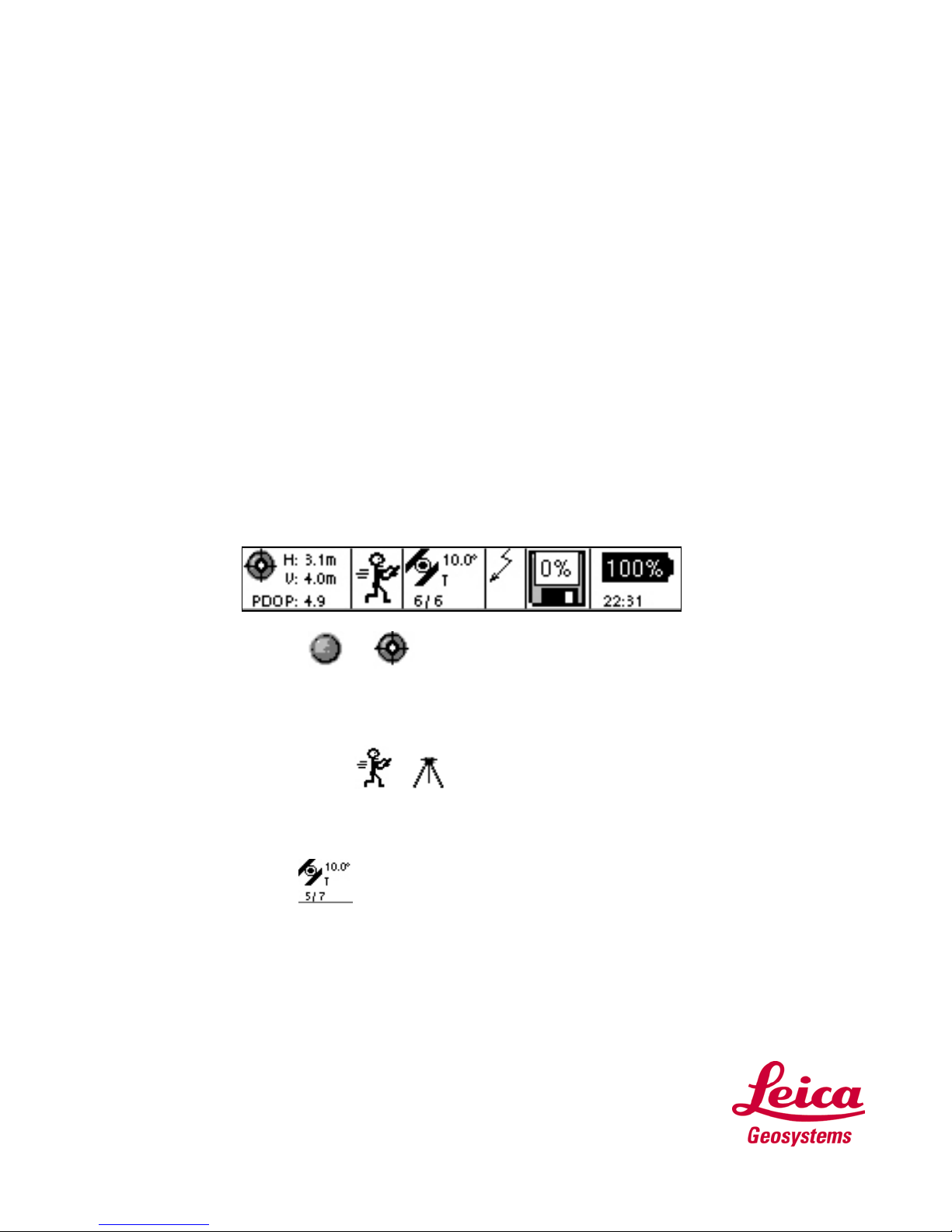
When differential corrections are received and interpreted, the differential icon appears. If the correction is
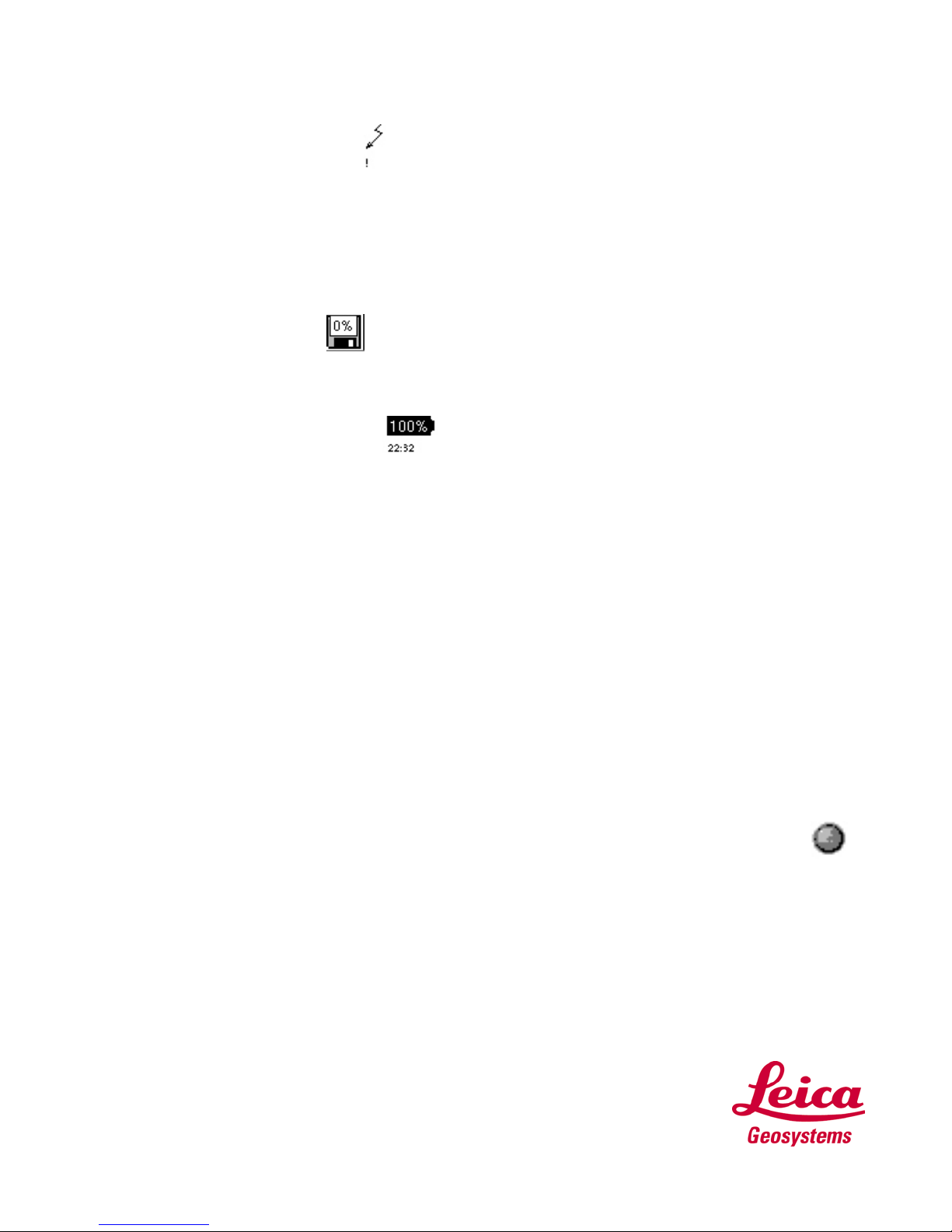
lost after 1/3 of the selected age (see 6.5.1), an exclamation point will appear in the lower left hand corner
of the window. If it is still absent after 2/3 of the selected age, an additional exclamation mark will appear.
If corrections are lost beyond the selected age, a third exclamation will appear and the icon will then
disappear.
This window will be empty when using Autonomous GPS or the Post Processing configuration.
Memory Card Status
The memory card status icon provides a graphical representation of the percentage of the compact flash
used.
Battery and Time Indicators
The battery and time indicators provide information about the current status of the onboard battery and
the current time obtained by satellites.
•Because the Battery indicator is based on a microprocessor in the Lithium Ion battery, only the onboard
battery status can be provided in percentages.
•Because the Leica Geosystems GS20 does not rely on internal batteries for clock function, time is only
displayed when 1 or more satellites are tracked.
GETTING YOUR FIRST POSITION
In order to collect Data, it will be necessary to have a GPS Position.
Power on the GS20 outside with a clear sky view and the receiver will begin to track satellites and
calculate a position.
Remember, if this is your first time tracking you will need to download an Almanac.
(See above section ALMANAC for further explanation)
After a few minutes, check to see if the position icon is displayed in the upper left of the Icon Panel.
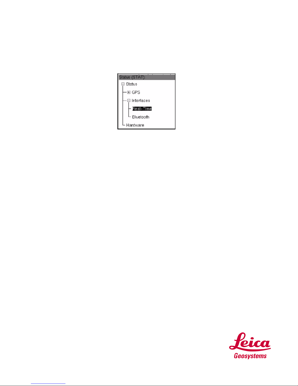
If it is, you have a position and are ready to collect data. The position can be viewed by selecting
Status|GPS|Position.
The position screen provides coordinate information containing:
•Coordinate system toggle
•Current time
•X,Y coordinates
•Ellipsoidal Elevation (EHeight)
•Position and Height Quality

If there is no position available, check the number of satellites to make sure you are tracking.
This can be seen by selecting Staus|GPS|Satellite View or by simply checking the Satellite Indicator.
Connecting to WoRCS Real Time Satellite (RTS)
If you purchased the Leica Geosystems GS20 with the Wireless real-time Correction System, the
WoRCS, you are only steps away from collecting real-time sub-meter data. The WoRCS comes pre-
configured with the Blue- tooth linked to your GS20.
Powering on the WoRCS
1.The Bluetooth Module is the only belt item with configurable controls. By Default, Power should be set
to On, and Line should be set to Bluetooth.
2.Follow the procedure listed previously for charging the batteries. Once the batteries are fully charged,
you can place them in any of the three bays of the battery insert shown below. The battery insert is both
hot swappable and self-switching. The batteries will be drawn down from bay one to bay three without
interruption in power.

Checking the Bluetooth Link
If your Bluetooth link is successfully connected, a status message “Bluetooth Link Restored” will appear
at the bottom of the screen. You can now proceed to Checking the real-time Link; if not follow the steps
listed below.
1.Power on the GS20 and select 4 Auxiliary, 4 Hard-ware, and the Wireless Selection.
2.Expand the Wireless tree, expand the Bluetooth, and view WoRCS.
3.If the GS20 has been linked to the WoRCS Bluetooth Module (see page 35), an address that
corresponds to the address on the top of the Bluetooth Module will appear. If the address does not
correspond, press menu and select clear.
4.If the address area displays zeros, you will need to establish a connection.
5.Highlight the WoRCS branch and press enter; this will take you to the Bluetooth Setup screen.

6.Press Inquire and wait until the Cancel button becomes Inquire again.
7.You will see the Available Devices in the choice list. By highlighting the available devices and pressing
Enter, you will see the entire list of available bluetooth devices in the choice list. If multiple devices have
been found, select the device that matches your WoRCS bluetooth address, displayed on the top of the
bluetooth module.
8.Finally, press the Menu key and Save, then Escape back to the main menu.
TIP: Ensure batteries are charged and correctly inserted. Ensure bluetooth module is set to line and on.
The single flashing red light indicates that power is available. When the light changes to green a BLUE-
TOOTH connection is established but no data is exchanged. When both green lights are flashing data is
exchanged.
Checking the WoRCS Realtime Link
Once the Bluetooth Link is established, you will need to make sure that your real-time device is linked
and active. If the status message “Reference Data is Available” appears, setup is complete, and there is
no need to proceed any further. Otherwise, follow the steps of the status check below.

WoRCS RTS
1. From the Main Menu select Status. Expand the Interfaces branch and select Real-Time. If you
have communication with the RACAL module (RTS), you will see information about the Station
ID, frequency, signal strength etc.
The real-time screen does not refresh automatically; to refresh the values, you will need to escape
and re-enter.
2. If the Station = -1, this means the Racal Unit does not have a subscription. You will need to
contact Racal-LandStar to check the status of your subscription. To find the office nearest you, go
to www.landstar-dgps.com.
3. If the station id is present and all lights are on, on the RACAL Module, escape to the Main Menu
and select 5 Setup.
Verify the user-defined configuration named “WRCSRTS” is selected; if WRCSRTS exists and
is not selected, highlight and press Enter, otherwise select the default “RACAL”.
4. Press Enter again on the selected configuration to edit the setup values.
5. Expand the Interfaces branch, highlight the Real-time branch and press enter.
6. Make sure the Device is set to RTS, and the port is set to WoRCS 1.
7. Escape and save the values, then escape and save the configuration.
If you are editing a default configuration, you will be prompted to provide a configuration name.
8. Escape to the main menu, and return to the status/Interface/Real-time branch to check the status
of the real-time device. You should now see values for the Station ID, frequency, bitrate, etc.

Collecting Data
Job Management
When Data Collection is opened, if no job is currently selected, the user will be prompted to either “Open”
an existing job or create a “New” job to continue. If a new or empty job is selected, the unit will prompt the
user to attach a codelist; otherwise the program will proceed to the Data Collection map.
Code Management
Because the Leica Geosystems GS20 is designed for GIS data creation and update, existing feature
layer will be used as a code template for each particular job. Additional codelists can be attached to a job
via Codelist Manager. In order to protect database integrity, a consistency check is performed when
codelists are attached to a job. If the same code occurs in both the feature table and the codelist, the job
feature data will be used. Codelists can be attached and detached as well as created and modified from
the Codelist Manager in the Auxiliary Menu.
The Job Codelist
If a job is new (i.e. does not contain any data), the user will be taken to the code table; otherwise the user
is defaulted into a map view. From the mapview, you can enter featuring via the context menu, or by just
pressing Enter. From the code table screen, the code template can be selected by using the cursor or
searching with the pop-up dialog (which opens with an alpha numeric key).

Attribution
After a code is selected, press Enter to open the attribution screen. By default the focus is on the Occupy
button; however, by using the cursor and Enter key, attribution values can be entered. Additional
occupation selections can be accessed via the context menu.
Point Collection
Point collection is often as simple as entering attributes, pressing Occupy and Save; however different
user defined quality settings can determine how the feature is collected (see Setup\Data Collection.) In
addition to direct locations, the user can also choose from a list of point offsets.

Line and Area Collection
Unlike point collection, lines and areas offer multiple methods of collection; noding (i.e. collecting by
vertex), streaming by time or distance, locating nodes by point offsets, creating linear offsets to either side
of the collected line, pasting a node from the clipboard, and nesting additional features. Because the
Start/Stop button is necessary to both stop in noding and pause in streaming, features must be saved by
the Done button or the Save Feature in the context menu.
Tip: When escaping the feature collection, a dialog will allow the user to save or discard the current
feature.

Modes of Collection
When a line or area feature is selected, the attribution screen will display the current mode of collection
(i.e. stream or node.) The last selected mode becomes the default by being stored in the user’s recent
value file.
2 Node Mode or noding is the manual collection of nodes or “vertices.” Like points, nodes can be
collected using the autostop which can be found in Data Collection\Quality Control settings in the Setup
menu.
3 Streaming is the automatic collection of nodes (i.e. vertices) based on time or distance (length between
nodes.) Additionally, streaming criteria can be based on the horizontal quality defined in the Data
Collection\ Quality Control in the Setup configuration. Streaming options can be selected from the
attribution\collection screen via the context menu.
4 Line Offsets allow the user to enter linear offsets, either left, right or in both directions with different
values. When in node mode, the offset selection will become a submenu offering all methods of point
collection for individual nodes. The 8 More selection allows the user to Paste from Clipboard, as well as
Append or Prepend an existing line. Paste from Clipboard allows multiple features to share common
nodes. In order to paste a node, it must first be 3 Copied to Clipboard in Data Management. (See
3.2.4.2)
Remember: Point features cannot be created with pasted node data in Data Collection.
Other manuals for GS20
1
Table of contents
Other Leica GPS manuals

Leica
Leica mojo3D User manual

Leica
Leica T-Scan5 User manual

Leica
Leica GPS500 User manual

Leica
Leica Digilux 2 User manual

Leica
Leica GPS1200+ Instructions for use

Leica
Leica GPS System 500 User manual

Leica
Leica GS09 User manual

Leica
Leica mojo3D User manual

Leica
Leica T-Scan 5 User manual

Leica
Leica GG02 User manual

Leica
Leica GPS1200 Series User manual

Leica
Leica MojoMINI User manual

Leica
Leica GPS1200 Series User manual

Leica
Leica mojo 3D User manual

Leica
Leica GPS1200 Series Product manual

Leica
Leica iNEX User manual

Leica
Leica DistoX2 User manual

Leica
Leica MojoMINI Installation and operating manual

Leica
Leica MX400 User manual

Leica
Leica INEX 1-1296 User manual