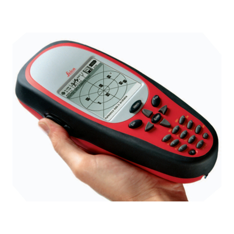
Leica MX400 User manual

Operator’s
Manual
MADE TO MEASURE
MX400 GPS Navigator

Operator’s Manual
DGPS Navigator
Version 3.3
ProductInformation
The model and serial number of your instrument are given on
the instrument. Enter the model and serial number in the
spaces provided below. Always refer to this information
when you contact your dealer.
Receiver Serial No.:______________
Part No.: _______________
Document No. 10500MAN
MX400 Series GPS
MX400
MX400B
MX412
MX412B
MX412BR

Symbols Used In This Manual
Danger
Indicates an imminently hazardous situation which, if not avoided,
will result in death or serious injury.
Warning
Indicates a potentially hazardous situation which, if not avoided,
could result in death or serious injury.
Caution
Indicates a potentially hazardous situation which, if not avoided,
may result in minor or moderate injury and/or appreciable material,
financial and envirtonmental damage. This symbol is also used to
alert against unsafe practices.
Important paragraphs which must be adhered to in practice as they
enable the product to be used in a technically correct and efficient
manner.
!
!
!
!This manual contains important safety directions as well as instruc-
tions for setting up the instrument and operating it. Read carefully
through the Operator’s Manual, Options Manual, and Installation
& Service Manual before you switch on the instrument.

Scope Of This Manual
This manual reflects the software capabilities in version 3.2
software.
We have attempted to take care and develop manuals which provide
in-depth information. Where possible, we have attempted not only
to describe what you see on the screen, but how to understand or
use it as well. Obviously, we can’t teach you how to navigate, but
we can help make your work more thorough and enjoyable.
Throughout the manual, you will find helpful hints about the
interaction of various functions. In a piece of equipment that has the
many capabilities of this receiver, important details can sometimes
become obscured in one or two lines of text. In our effort to ensure
you get the most out of this documentation, and protect against
important details becoming lost, don’t be surprised if you see the
same or similar information more than once.
This manual is organized by describing the special front panel
features first. The sections that follow detail each primary function
as it is presented on the front panel (i.e. NAV, RTE, WPT, PLOT,
...CFG). The appedixes describe important details about special
functions. Details of any product options that are available at an
additional modest price are provided in a separate Options Manual
(see Related Documents below).
We hope you find the manual enjoyable and informative reading.
As always, we welcome your comments on improving our products
or manuals. We wouldn’t mind if you wrote to tell us that we did
the job right the first time either. You can find a Reader Comment
Card at the back of the manual.
RelatedDocuments
Installation & Service Manual (P/N 10501MAN)

How To Contact Us
For Installation, Service, & Technical Support:
Contact your local Leica dealer
For Sales of accessories:
Contact your local Leica dealer
For Hardware and Software Upgrades:
Contact your local Leica dealer
Unlike many other consumer electronics industries which only sell
consumer electronic devices, your marine dealer is often your best
advisor for installation and service of your new GPS receiver. Leica
strongly encourages you to utilize the knowledge and experience of
your sales and service dealer.
Should you need to contact us directly, we can be reached at the
following for new sales, upgrades, repair service, or technical
support:
International:
Leica Geosystems
GPS
23868 Hawthorne Blvd.
Torrance, California 90505
USA
+01-310-791-5350 Telephone (International)
1-800-97-LEICA (1-800-975-3422) Telephone (USA)
+01-310-791-6108 Fax
In Europe:
Leica Geosystems
A/S
Høkær12A
DK-2730 Herlev
Denmark
+45-44-54-03-00Telephone
+45-44-54-03-30 Sales Fax

Version 3.3 i
Table of Contents Operator’s Manual
Table of Contents
Product Information ........................................................................ i
Symbols Used In This Manual........................................................ii
Scope Of This Manual...................................................................iii
Related Documents.......................................................................iii
Scope Of This Manual...................................................................iii
Related Documents.......................................................................iii
How To Contact Us........................................................................iv
About GPS Navigation................................................................1
Special Notes ................................................................................ 2
GPS .............................................................................................2
DGPS........................................................................................... 2
Charts and NavigationalAids....................................................... 3
Functional Description ................................................................4
ReceiverConfigurations..................................................................4
6 Channel GPS ............................................................................. 4
6 Channel GPS With Built-in Beacon ............................................ 4
12 Channel GPS ........................................................................... 4
12 Channel GPS With Built-in Beacon .......................................... 5
6 Channel Dual Control................................................................. 5
12 Channel Dual Control............................................................... 5
12 Channel Dual Control Integrity Monitor .................................... 6
DGPS Beacon System ...............................................................8

ii Version 3.3
Operator’s Manual Table of Contents
Keypad & Display Description...................................................10
Differential GPS Traffic Light Operation: ..................................... 11
Red Flashing.............................................................................. 11
Red/Yellow Solid ........................................................................ 11
Red Solid ................................................................................... 11
Yellow/Green Solid..................................................................... 11
Yellow Solid................................................................................12
Green Solid ................................................................................12
GPS Traffic Light Operation: ....................................................... 12
Red Flashing..............................................................................12
Red/Yellow Solid ........................................................................ 13
Red Solid ...................................................................................13
Yellow Solid................................................................................13
Green Solid ................................................................................13
The Display: ................................................................................ 14
The Softkeys: ..................................................................... 14
The Function Keys: ..................................................................... 14
Mark Position.................................................................. 15
GOTOO.............................................................................15
LIGHT .............................................................................15
POWER ON/OFF............................................................ 16
MAN OVER BOARD (MOB) ...........................................16
E
E (EDIT)..........................................................................17
C
C (CLEAR)......................................................................18
CURSOR ........................................................................18
NAV
1
ABC FUNCTION .....................................................................18

Version 3.3 iii
Table of Contents Operator’s Manual
Navigate ...................................................................................20
Dead Reckoning............................................................................21
NAV1 - The Panorama Screen......................................................22
NAV2 - Basic Steering Information................................................24
NAV 3 - Expanded Navigation Information ....................................26
NAV4 - Sensor Input Navigation....................................................27
Route........................................................................................31
RTE1-TheActiveRoute...............................................................32
CreatingA Route Using The GOTO Key: .................................... 33
Erasing An Existing Route........................................................... 36
CreatingA Multi-Waypoint Active Route...................................... 37
Insert By Number ........................................................................ 38
Choose In Bank........................................................................... 39
Insert New Waypoint ................................................................... 40
Insert Route................................................................................. 41
Maneuvering Within The Route................................................... 42
Scrolling .....................................................................................42
Skipping and Unpassing Waypoints........................................... 42
Inserting Waypoints or Routes IntoAn Existing Route...............43
Reversing The Active Route....................................................... 46
ETA Setup .....................................................................................47
SOG Based on Arrival Date & Time: ........................................... 48
ETA Based on Speed: ................................................................. 48
RTE2 - The Route Bank ................................................................49
Waypoint...................................................................................51
CreatingAndEditingWaypoints....................................................52
Waypoint Lock/Unlock................................................................. 57
To lock a waypoint......................................................................58
To unlock a waypoint..................................................................58
To lock all waypoints .................................................................. 59
To unlock all waypoints .............................................................. 59

iv Version 3.3
Operator’s Manual Table of Contents
RemovingWaypoints.....................................................................60
Movingwaypoints..........................................................................61
Downloading Waypoints & Routes To Other Devices....................63
Rnn - Routes:.............................................................................63
RTE - Active Route:.................................................................... 64
WPL - Waypoint Location - NMEA 0183 Standard:....................65
WPL - Waypoint With Symbols &
Description - NMEA 0183 Expanded: .................................. 65
Downloading Waypoints To A Personal Computer ...................... 66
Uploading Waypoints From Other Devices....................................68
Uploading Waypoints From A Personal Computer ...................... 69
Mark or Event ..................................................................71
GOTOO..............................................................................72
Plot ...........................................................................................75
PLOT 1 - Relative To Boat.............................................................77
Modifying The Active Route Using The Plot Screen.................... 77
Customizing The Display............................................................. 79
PLOT 2 - Relative To Marker.........................................................82
Plot Screen Use Examples............................................................82
Station Keeping ........................................................................... 82
Grid Search ................................................................................. 83
Man Over Board...............................................................85
Remote MOB ................................................................................86
Tide ..........................................................................................87
TIDE1 - Current Tide Display ........................................................87
TIDE2 - Tide Table Port List ..........................................................88
AddingA Port ................................................................................90

Version 3.3 v
Table of Contents Operator’s Manual
Auxiliary....................................................................................92
AUX1 - Alarm Log...................................................................... 92
AUX2 - Speed Graph .................................................................. 93
AUX3 - Fuel Information.............................................................. 93
AUX4 - Sun Almanac................................................................... 94
AUX5 - Moon Phases.................................................................. 94
AUX6 - Batteries.......................................................................... 94
AUX7 -Unit Information ............................................................... 95
Position.....................................................................................96
POS1 - Large Position Display......................................................97
Loran-C ....................................................................................... 97
User Grid ..................................................................................... 98
UTM............................................................................................. 98
Decca .......................................................................................... 99
POS2 - Position, Altitude,Magnetic Variation, & Time ..................99
POS3 - Position & Log ................................................................100
GPS........................................................................................102
GPS1 - Current Satellite Status...................................................102
For 6 Channel GPS Models ...................................................... 102
For 12 Channel GPS Models .................................................... 104
GPS2 - GPS Health (All Models).................................................105
DGPS.....................................................................................109
DGPS1 - Current DGPS Correction Status .................................109
DGPS3 - DGPS Messages .........................................................112

vi Version 3.3
Operator’s Manual Table of Contents
Configuration.......................................................................... 113
Alarms.........................................................................................113
Anchor-Anchor WatchAlarm .....................................................114
COG SOG - Course & Speed Filter Settings & Setup.................114
Compass - External Compass Input & Magnetic
VariationTable ......................................................................115
Datum - Current Position Calculation ..........................................116
Depth - NMEA Input Control........................................................117
DGPS - Differential Correction Input Control...............................118
DR - Dead Reckoning .................................................................121
Dual Contr. - Dual Station Control ...............................................123
Fuel - Fuel Input Calibration & Control ........................................123
GPS - Elevation Mask &Antenna Offset Control.........................125
Init Pos - Initial Position Entry......................................................126
Language - Foreign Language Setup..........................................127
Lighting - Display/Keyboard Light & Contrast Control .................128
Log - Speed Log Input (Pulse or NMEA 0183) ............................129
Log Pulses - GPS SOG Log Pulse Output ..................................131
MX 480 - MX 480 PC Chart Interface Control .............................131
Navigation - Navigation Method & Waypoint Pass
Criterion Control....................................................................131
NMEA Out 1 thru 4 - NMEA 0183 Output Data Control...............135
Other Special CasesAffecting NMEA 0183 Records: ............... 140
Operation - General SetupAnd Control Settings.........................141
Organizer-AutomatedMessageReminders ..............................143
Position - Positioning Reference, Mode, & AlarmControl ...........144
Printout 2 - Printer Output Control...............................................146

Version 3.3 vii
Table of Contents Operator’s Manual
Security .......................................................................................149
Set & Drift....................................................................................149
SJB - Smart Junction Box Control...............................................150
Time - ModeAnd Format Control ................................................152
Wind............................................................................................153
Wpt & Rte Input - Uploading Waypoints Into the receiver ...........154
AppendixA - Datum List .........................................................155
Appendix B - Beacon List .......................................................162
Appendix C- Engineering Mode..............................................175
AUX7 - Unit Information & Self Test ............................................175
Receiver Cold Start - Clearing Memory To Factory Default.........177
GPS - GPS Receiver Troubleshooting ........................................178
GPS6 - Visible Satellite Information .......................................... 178
GPS7 - GPS Position Uncertainty ...............................................179
GPS8 - Oscillator Offset Temperature Curve Fit..........................180
GPS9 - GPS Debug Screen........................................................181
DGPS8 - Beacon Receiver Status ..............................................183
Beacon Signal Scope..................................................................184
Appendix D - Dual Control Head Mode...................................186
Turning Master And Slave Units Off ............................................188
Appendix E - Demonstration Mode.........................................189
Appendix F - Software Updates..............................................191
Glossary .................................................................................196

viii Version 3.3
Operator’s Manual Table of Contents

Version 3.3 1
About GPS Navigation Operator’s Manual
About GPS Navigation
This GPS receiver is a precision navigation instrument utilizing the
latest technology available today to provide optimum performance
from the GPS satellite and Beacon land signals received. As with all
other forms of radio signals, the ultimate navigation result is
dependent upon the quality of these signals. Radio signals may, on
occasion, be distorted, jammed, or otherwise incorrect. As a result,
your position accuracy may occasionally be less than that which can
normally be expected.
The Navstar Global Positioning System, commonly referred to as
GPS, is a satellite navigation system developed by the U.S. Depart-
ment of Defense to provide both military and civilian users with
highly accurate, worldwide, three dimensional navigation and time.
By receiving signals from orbiting GPS satellites, authorized users
are able to continuously navigate with an accuracy on the order of
16 meters or better, while civilian users are limited to accuracy’s of
approximately 100 meters 2D RMS.
A technique referred to as Differential GPS (DGPS), allows users to
obtain maximum accuracy from the GPS system. DGPS requires
the use of two GPS receivers. One receiver, known as the Reference
Station, is placed at a surveyed location, the coordinates of which
are precisely known. The purpose of the differential GPS system is
to use the reference station to measure the errors in the GPS signals
and to compute corrections to remove the errors. The corrections
are then communicated in real-time to the navigators, where they
are combined with the satellite signals received by the navigators,
thereby improving their navigation or positioning. This technique is
effective because many of the errors at the reference station and
navigators are common. The geographic validity of these correc-
tions decreases with distance from the reference station, but the
corrections are valid for navigators hundreds of kilometers from the
reference station.
In order to set up a DGPS system, the user must have a GPS
reference station at a precisely known location, a DGPS navigator,
and a communication link to transmit the pseudorange corrections.
Leica has pioneered the development of the DGPS Beacon System.
This system allows the user to benefit from the accuracy of DGPS
without the need to purchase and maintain a complete DGPS
System (reference stations, transmitting equipment, as well as
!

2Version 3.3
Operator’s Manual About GPS Navigation
receiving equipment, and navigators).
Marine radio beacons operating in the 283.5 to 325.0 KHz fre-
quency range are in widespread use for direction finding in coastal
navigation. Because the beacon system has been in place and
widely used for many years, it provides an effective means for the
transmission of DGPS signals. Depending on their local environ-
ment and power output, their signals may be usable to several
hundred miles. Marine beacons provide an economical means of
obtaining DGPS accuracy for coastal navigators. GPS receivers
with built-in beacon receivers are designed to provide low cost
reception of DGPS corrections broadcast (normally free of charge)
by coastal authorities.
Special Notes
GPS Never rely solely on any single navigational aid. Always use
whatever information is available, and cross-check information
when possible. GPS expected position accuracy is better than 100
meters (95% of the time); but may be up to 300 meters occasion-
ally. The derived speed and course readings may be hampered
accordingly. The GPS system was declared operational in 1994,
however, the system’s availability and accuracy are subject to
change at the discretion of the US Department of Defense.
DGPS This GPS receiver’s position accuracy is improved to 5 meters or
better for 95% of the time, subject to the availability, accuracy, and
control of the DGPS correction transmission from the Beacon
Station, or other reference station connected at the time of usage.
The differential GPS position is that of the navigator GPS antenna,
and not that of the beacon antenna, if a separate beacon antenna is
in use. In addition, the beacon radio signal which carries the DGPS
corrections may be hampered by weather conditions such as heavy
rain, snow, and thunder storms. The beacon radio signal may also
be interrupted by powerful radio transmitters operating in long
!
!

Version 3.3 3
About GPS Navigation Operator’s Manual
wave length bands.
Charts and NavigationalAids
Positions obtained from charts are not always as accurate as your
navigator (due to environmental changes, the dates of charts, and
datum offsets if the datum differs from the one in use by the
navigator). The position of a floating aid can differ due to tide, set
and drift.
!

4Version 3.3
Operator’s Manual Functional Description
Functional Description
Receiver Configurations
This GPS receiver is available in six basic configurations, identified
by product description and part number. Refer to the Auxiliary Unit
Information section of the manual to view sample screens to
identify your particular model.
6 Channel GPS
The basic 6 channel GPS navigator is capable of receiving DGPS
corrections in the RTCM SC-104 version 2 format via one of the
four input data ports. However, it does not have an internal marine
beacon DGPS receiver. This model is supplied with a GPS only
Volute, Discus, or Globe style antenna. Should you decide at a later
date to upgrade your receiver to a GPS with Built-in Beacon, the
display unit must be returned to the factory to install the appropriate
components and software. In addition, a separate whip, loop
(optional), or combined (optional) antenna is supplied with the
upgrade. This model can be upgraded to a 12 channel GPS model in
the field, by purchasing a 6 channel baseband daughter board (P/N
10502).
6 Channel GPS With Built-in Beacon
This is a standard 6 channel DGPS navigator with an integrated
internal beacon receiver. It is capable of receiving DGPS correc-
tions in the RTCM SC-104 version 2 format via its internal marine
beacon DGPS receiver, or via one of the four input data ports. This
model is supplied with a GPS and Loop (H-Field) combined Discus
style antenna. A separate (optional) whip or loop antenna may be
used with this model; however, an additional internal cable must be
installed in this configuration. This model can be upgraded to a 12
channel GPS model in the field, by purchasing a 6 channel
baseband daughter board (P/N 10502).
12 Channel GPS
This is a 12 channel GPS upgraded version of the basic 6 channel
GPS navigator. It is capable of receiving DGPS corrections in the
RTCM SC-104 version 2 format via one of the four input data

Version 3.3 5
Functional Description Operator’s Manual
ports. However, it does not have an internal marine beacon DGPS
receiver. This model is supplied with a GPS only Volute, Discus, or
Globe style antenna. Should you decide at a later date to upgrade
your 6 channel to a 12 channel receiver or your 12 channel receiver
to a 12 channel with built-in beacon, the display unit must be
returned to the factory to install the appropriate components and
software. In addition, a separate whip, loop (optional), or combined
(optional) antenna is supplied with this upgrade.
12 Channel GPS With Built-in Beacon
This is a 12 channel GPS upgraded version of the standard 6
channel with built-in beacon DGPS navigator. It is capable of
receiving DGPS corrections in the RTCM SC-104 version 2 format
via one of the four input data ports, or via its internal marine beacon
DGPS receiver. This model is supplied with a GPS and Loop (H-
Field) combined Discus style antenna. A separate (optional) whip or
loop antenna may be used with this model, however, an additional
internal cable must be installed in this configuration.
6 Channel Dual Control
This is an enhanced 6 channel DGPS navigator. Two GPS receivers
are actually supplied, one 6 channel GPS (operating as a slave unit)
and one 6 channel with built-in beacon (operating as a master unit)
with one GPS and Loop (H-Field) combined Discus style antenna.
It is capable of receiving DGPS corrections in the RTCM SC-104
version 2 format via one of the four input data ports, or via its
internal marine beacon DGPS receiver. This configuration allows
data to be shared between two remotely separated stations (i.e.
navigator’s station and helmsman’s station), with independent
access to various information fields. The 6 channel GPS unit gets its
positioning information from the 6 channel GPS with built-in
beacon unit, but can be connected to the antenna independently and
calculate its own position as a back-up GPS receiver. This model
can be upgraded to a 12 channel GPS model in the field, by
purchasing a 6 channel baseband daughter board (P/N 10502).
12 Channel Dual Control
This is a 12 channel GPS upgrade to the enhanced 6 Channel Dual
Control configuration. It is a dual head DGPS system where two
GPS receivers are actually supplied, one 6 channel GPS (operating

6Version 3.3
Operator’s Manual Functional Description
as a slave unit) and one 12 channel with built-in beacon (operating
as a master unit) with one GPS and Loop (H-Field) combined
Discus style antenna. It is capable of receiving DGPS corrections in
the RTCM SC-104 version 2 format via one of the four input data
ports, or via its internal marine beacon DGPS receiver. This
configuration allows data to be shared between two remotely
separated stations (i.e. navigator’s station and helmsman’s station),
with independent access to various information fields. The 6
channel GPS gets its positioning information from the 12 channel
with the built-in beacon, but can be connected to the antenna
independently and calculate its own position as a back-up GPS
receiver.
12 Channel Dual Control Integrity Monitor
This is an enhanced to the 12 Channel Dual Control configuration.
It is a dual control DGPS system where two DGPS receivers are
supplied, one 12 channel with built-in beacon (operating as a slave
unit) and one 12 channel with built-in beacon (operating as a master
unit) with two GPS and Loop (H-Field) combined Discus style
antennas. It is capable of receiving DGPS corrections in the RTCM
SC-104 version 2 format via one of the four input data ports, or via
its internal marine beacon DGPS receiver. This configuration
allows data to be shared between two remotely separated stations
(i.e. navigator’s station and helmsman’s station), with independent
access to various information fields. The purpose of this configura-
tion is for each receiver to calculate its own position, then to check
the operational status of the other GPS receiver. The GPS receiver
with the best overall operational status then provides the system
position. This provides a fully redundant system, with self-recovery
capabilities. The Integrity Monitor function can be set to Automatic
switchover, forced to the Master unit, or forced to the Slave unit for
position and navigation functions.
The Installation & Service Manual has more details on the parts
supplied with each configuration, and their associated part numbers.
Beyond the physical differences between these models, the operat-
ing software is exactly the same, except where the hardware
differences mentioned above come into play. Expect to find these

Version 3.3 7
Functional Description Operator’s Manual
differences detailed in the GPS, DGPS, & CFG sections of the
manual.
Note: In general, this manual will refer to all versions
of this product line simply as the receiver,
navigator, or GPS. Where distinction between
models is necessary, the particular model type
will be called out.
Table of contents
Other Leica GPS manuals

Leica
Leica GPS System 500 User manual

Leica
Leica mojo 3D User manual

Leica
Leica T-Scan5 User manual

Leica
Leica GPS500 User manual

Leica
Leica GPS1200 Series User manual

Leica
Leica apMK12 User manual

Leica
Leica GPS1200+ Product manual

Leica
Leica DistoX2 User manual

Leica
Leica MojoMINI User manual

Leica
Leica iNEX User manual

Leica
Leica Digilux 2 User manual

Leica
Leica GG02 User manual

Leica
Leica GPS1200 Series Product manual

Leica
Leica MojoMINI User manual

Leica
Leica GS20 User manual

Leica
Leica MojoMINI Installation and operating manual

Leica
Leica mojo3D User manual

Leica
Leica GS09 User manual

Leica
Leica RX1250 SmartRover User manual

Leica
Leica INEX 1-1296 User manual