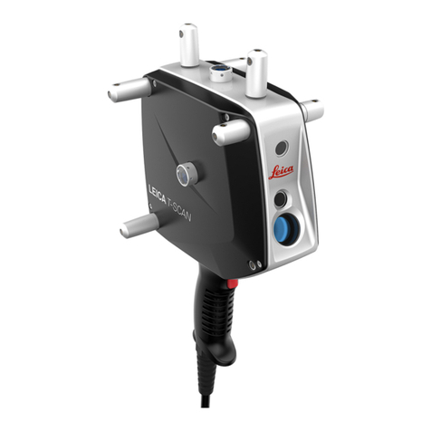
Leica T-Scan5 User manual

392
SPATIALANALYZER USER MANUAL
T-Scan Interface
Hardware Setup
This Quick-start guide can be used for the initial setup of the Leica
T-Scan5 system for operation within SA in conjunction with either an
AT960 or AT901.
Set up the unit following the manufacturer’s directions. The
AT960 users the MCA-47 cable between the T-Scan and Tracker
controller’s signal port (the trigger port is not used). The AT901
uses the MCA-36 cable which has a dual end for the tracker sig-
nal line and trigger connections . A single network cable should
be connected from the computer to the t-scan controller and a
second Ethernet cable connects the tracker and t-scan system
along with a signal cable (Figure 14-82).
Figure 14-82. AT901 Cable
Conguration
Ensure that you have the T-Scan License key to operate the sys-

393
CHAPTER 14 MEASURING WITH LASER TRACKERS
tem.
Ensure that you have the USB drive containing the *.mtx and
*.emsys les (calibration les) which should also contain the
Leica setup manuals and a version of the required software (T-
Scan Collect or T-Scan Interface and TwinCat Engineering).
Tracker Conguration
The T-Scan target denition must be dened on the tracker controller.
The procedure to do so depends on the tracker type:
AT960 Conguration:
1. Open Tracker Pilot, and connect to the AT960 using the “Ad-
vanced”permissions (if you need the current Tracker Pilot you
can browse directly to http://192.168.0.1 (or the trackers IP)
and download Tracker Pilot from the controller).
2. Go to targets and ensure the T-Scan is dened. If not use the
Import Targets button and browse to the *.emsys le for the
t-scan provided on the USB disk.
3. Once dened Exit Tracker Pilot.
AT901 Conguration:
1. Open the Emscon TransferTool, enter the tracker IP and press
Test.
2. In the Transfer to emScon section press Parameter File and
browse to the *.emsys le for the t-scan provided on the USB
disk.
3. Save and Exit
Software Setup and Initial conguration
Directory Setup:
1. Determine if you have a license key for either the T-Scan In-
terface or the full T-Scan Collect Software (Either one or the
other should be installed as require but not both), and install
the correct one on your machine.
2. Transfer the *.mtx les from the USB drive to the T-Scan direc-
tory. T-Scan looks for the les in a particular spot (C:\Program-
Data\Steinbichler\T-SCAN\Calibration) you will need to build
the Calibration directory and place the les in this folder.
TScanCol.ini Edit Process:
1. Within the C:\ProgramData\Steinbichler\T-SCAN\T-SCAN In-
terface 10.30\ folder (or T-Scan Collect 10.3 folder) you will
nd a le called “TScanCol.ini”. Open and edit this le as fol-
lows (it’s a long le so scroll through it to the correct section):
2. Verify the Specic IP address of your tracker (192.168.0.1 by

394
SPATIALANALYZER USER MANUAL
default)
3. Enter the TrackerInterfaceType (EMSCON for AT901 or LMF for
AT960)
4. Enter the ScannerAlignmentBaseName (such as LLS1100271).
This number is on the front of the T-Scan.
5. Enter the AMSNETID for theT-Scan Controller.Which should be
printed on the front of the controller (Such as 5.29.142.116.1.1)
6. Once complete save and close the TScanCol.ini le (see Figure
14-83).
Figure 14-83. TScanCol.ini le
Network Conguration:
1. Congure your local area network connection as follows:
2. Go to Control Panel> Network and Internet> Network and
Sharing Center
3. Open the Local Area Network Connection properties (ensure
the cable is connected to the T-Scan Controller if you don’t
see it)
4. Go to the properties for the Internet Protocol Version 4 (TCP/
IPv4)
5. Set the IP address to use the following IP: 10.168.2.2XX (enter
201-250 only) and subnet 255.255.255.0.
6. Press Advanced and add a second IP (for the tracker). En-
ter 192.168.0.XXX (enter 2-250 for the IP), again using
255.255.255.0 for the subnet mask(see Figure 14-84).

395
CHAPTER 14 MEASURING WITH LASER TRACKERS
Figure 14-84. Network Congu-
ration settings
7. Click OK and close out of all dialogs and exit out of the net-
work Sharing Center when done.
TwinCAT Software:
1. Install the TwinCAT Engineering Software (which will man-
age the dual network communication between the tracker
and the T-SCAN system). This software should be available
on your USB drive and will be called “Tc211x64Engineer-
ing_2110_2209.exe” or something similar.
2. From the Windows task bar launch the TwinCAT System Man-
ager and congure it to talk to the T-Scan Controller.
3. Select Choose Target(see Figure 14-85):

396
SPATIALANALYZER USER MANUAL
Figure 14-85. c
Figure 14-85.
c
4. Perform a Broadcast Search and look for the AMS NetID of the
controller which should show up on the network list. When it
does, select it and set it to use IP Address as follows(see Figure
14-86):

397
CHAPTER 14 MEASURING WITH LASER TRACKERS
Figure 14-86. c
Fi
Fi
Fi
Fi
gure 14-86.
c
5. You can tell you have a successful connection to both the T-
Scan Controller and the Tracker once you see the Status in-
dicator in the bottom right of the TwinCAT software report
a green connected status. At that point you can close out of
TwinCAT.
Running the T-Scan Interface in SA:
1. Add the Instrument (Instrument>Add…) and choose the ap-
propriate Leica Tracker (AT901 or AT960)
2. Start the Interface through the menu Instrument>Run Inter-
face Module and choose Leica TScan. (Do not connect using
the Laser Tracker Interface) (see Figure 14-87):

398
SPATIALANALYZER USER MANUAL
Figure 14-87. T-Scan Interface
Fi
Fi
Fi
Fi
Fi
gu
gu
gu
gu
gu
gu
gu
gu
gu
gu
gu
gu
gu
gu
gu
gu
gu
gugu
re
re
re
re
re
re
re
re
re
re
re
re
re
re
re
re
re
re
1
1
1
1
1
1
1
1
1
1
1
1
1
1
1
1
1
1
1
1
1
1
1
1
1
1
1
1
1
1
1
1
1
1
1
1
1
1
1
1
1
1
1
1
1
1
1
1
1
1
1
1
1
1
1
1
1
1
1
1
1
1
1
1
1
1
1
1
1
1
1
1
1
1
1
1
1
4-
4-
4-
4-
4-
4-
4-
4-
4-
4-
4-
4-
4-
4-
4-
4-
4-
4-
4-
4-
4-
4-
4-
4-
4-
4-
4-
4-
4-
4-
4-
4-
4-
4-
4-
4-
4-
4-
4-
4-
4-
4-
4-
4-
4-
4-
4-
4-
4-
4-
4-
4-
4-
4-
4-
4-
4-
4-
4-
4-
4-
4-
4-
4-
4-
4-
4-
4-
4-
4-
4-
4-
4-
4-
4-
4-
4-
4-
4-
4-
4-
4-
4-
4-
4-
4-
4-
4-
87
87
87
87
87
87
87
87
87
87
87
87
87
87
87
87
87
87
87
87
87
87
87
87
87
87
87
87
87
87
87
87
87
87
87
87
87
87
87
87
87
87
87
87
87
87
87
87
87
.
T-Scan Interfac
e
T-Scan Interface in SA:
When you start the Leica T-Scan interface it will automatically con-
nect to either T-Scan Collect or the T-Scan Interface which will run in
the background. The T-Scan interface in SA is designed to be as sim-
ple as possible while providing full control (see Figure 14-88):
Figure 14-88. T-Scan Interface
Fi
Fi
Fi
Fi
gure 14-88.
T-Scan Interface

399
CHAPTER 14 MEASURING WITH LASER TRACKERS
Collection and Cloud Name control is provided and a new
cloud name will be incremented automatically with each sepa-
rate scan.
A progress report will be displayed in the connection window
T-Scan control is provided through the Settings button. Con-
trol for both the TS50 and the new Tscan5 is available in sec-
tions in the left hand column, the following Tscan5 controls are
provided:
Exposure Time can be set manually from 0.25 to 20.0 mil-
liseconds
Line Width Set can be set from 0-12 (0=100%, 12=40%).
This reduces the width of the line as you increase the integer
value (set as an integer for scripting purposes).
Reection Filter intensity setting (1 = Standard, 2 = Low, 3
= Medium, 4 = High). Again this value is set as a simple integer
for easy scripting control.
T-Scan MP Controls SA:
Start Instrument Interface. – Argument 3 controls the allow-
able interface types. Include 0 (laser tracker), 1 (Leica Automa-
tion Interface Control interface), or 2 (Leica T-Scan).
Instrument Operational Check –
Select Device T-Scan. – Set AIC Device Selection to T-Scan
Select Tracker # - Set AIC Tracker #, Jump SA Instrument to desig-
nated Collection::Instrument Index (set in AIC Driver), Connect
and Start Interface to T-Scan or emScon based on current MUX
and AIC Device Selection.
Increment Group/Cloud Name – Increment the current Group/Cloud
Name by 1.
Release Motors – Releases motors if there is a current emScon or
T-Scan connection.
Is Laser Locked – Returns success if the beam is locked. Status
window will indicate the kind of target the laser is locked onto.
Set Scan Point to Point Distance – T-Scan Point to Point Distance
Control
Set Scan Line to Line Distance – T-Scan Line to Line Distance Control
Set Scan Maximum Angle of Incidence – T-Scan Maximum Angle Con-
trol in Degrees
Set Scan Exposure Time [] – Set the scanner expose to a value from
0.25-20.0ms.

400
SPATIALANALYZER USER MANUAL
Set Scan Width Iteration []- Sets the width of the scan line as a re-
duction factor from 0-12 (where 0=100% and 12=40% of the
full scan width)
Set Scan Reection Filter [] – Sets the reection lter type from 1-4
(1=Standard, 2=low, 3=Medium, 4=High)
Close Scan Gaps Up To [] – Tells T-Scan collect to close gaps in scan
data to the specied mm distance. Enter 0 to not close gaps.
Scanner Power On – Turn T-Scan On
Scanner Power O– Turn T-Scan O
Set Instrument Group and Target – The Group name is used as the
Cloud Name when using the T-Scan
Measure – Causes the T-Scan to start scanning.
Stop Active Measurement Mode – Causes the T-Scan to Stop Scan-
ning.
Leica Automation Interface
Hardware Setup
Before starting the AIC driver, it’s necessary to ensure that all hard-
ware connections are complete:
The AT-901 tracker controllers should be connected to the AIC
hardware.
The auxiliary device (T-Mac, T-Probe, external trigger, etc.)
should be connected to the AIC hardware.
The AIC hardware should be directly connected to the com-
puter on which the interface will be run.
Starting the AIC Driver Manually
1. First, add up to four Leica AT-901 trackers to the SA job.
2. From the appropriate SA folder in the Windows Start Menu,
navigate to Interfaces and select Leica Automation Interface
(Figure 14-89).
3.
Figure 14-89. Starting the Leica
Automation Interface.
In the Connect dialog, select the tracker you’d like to connect
to (Figure 14-90).
Table of contents
Other Leica GPS manuals

Leica
Leica apMK12 User manual

Leica
Leica GPS1200+ Product manual

Leica
Leica GPS500 User manual

Leica
Leica MK8 User manual

Leica
Leica GPS1200 Series Product manual

Leica
Leica SR20 User manual

Leica
Leica GG02 User manual

Leica
Leica MojoMINI User manual

Leica
Leica GS20 User manual

Leica
Leica MojoMINI User manual

Leica
Leica GPS1200 Series User manual

Leica
Leica GPS1200 Series User manual

Leica
Leica iNEX User manual

Leica
Leica RX1250 SmartRover User manual

Leica
Leica DistoX2 User manual

Leica
Leica GS09 User manual

Leica
Leica Digilux 2 User manual

Leica
Leica T-Scan 5 User manual

Leica
Leica mojo3D User manual

Leica
Leica mojo 3D User manual