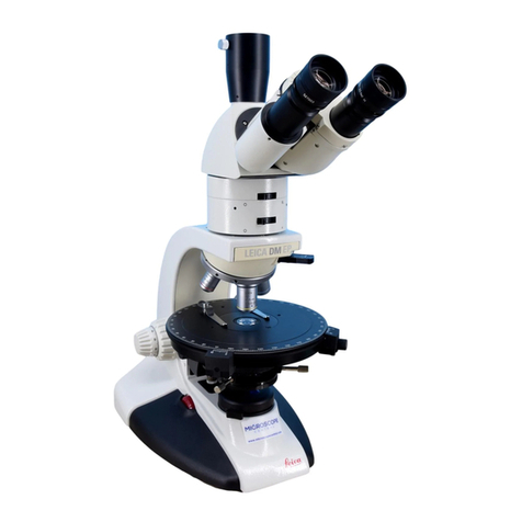
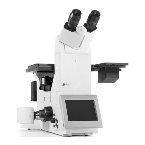
Leica DMLS User manual

MICROSYSTEMS
Leica DMLS
Instructions · Bedienungsanleitung
Mode d’emploi

Phone/Tel./Tél. +49 (0) 6441-290
Fax +49 (0) 6441-292255
4th edition, issued in 2000 by/
4. Auflage, herausgegeben 2000 von/
4ème édition, publiée en 2000 par:
Leica Microsystems Wetzlar GmbH
Ernst-Leitz-Straße
D-35578 Wetzlar (Germany)
Responsible for contents/
Verantwortlich für den Inhalt/
Département responsable du contenu:
Marketing MQM, Product management

3
MICROSYSTEMS
Leica DM LS
Instructions

4
Copyrights
4
All rights to this documentation are owned by
Leica Microsystems Wetzlar GmbH. Copying of
text and illustrations – in full or in part – by print-
ing, photostat, microfilm or other techniques, in-
cluding electronic systems, is only permitted
subject to the express written consent of Leica
Microsystems Wetzlar GmbH.
The information contained in the following docu-
mentation represents the latest stage of tech-
nology and knowledge. We have composed the
texts and illustrations with great care. However,
as it is impossible to eliminate the risk of error
completely, we cannot accept any kind of liabil-
ity for the correctness of the contents of this
manual. Nevertheless, we are always grateful to
be notified of any errors.
The information in this manual may be altered
without prior notice.

5
Contents
Important notes on this manual ....................... 7
Assembly an description
of components ..................................................... 8
Site ......................................................................... 8
Mains voltage, fuses .......................................... 9
Assembly of components .................................. 10
Light sources, lamp change.............................. 16
Performance parameters .................................. 22
Objectives, eyepieces ........................................ 22
Tube system ......................................................... 25
Condensers .......................................................... 26
Operation .............................................................. 28
Basic setting for transmitted light ................... 28
Filters ..................................................................... 30
Condensers .......................................................... 30
Phase contrast .................................................... 34
Transmitted light darkfield................................. 36
Transmitted light polarization ........................... 37
Fluorescence ....................................................... 38
Linear measurements ........................................ 42
Thickness measurements ................................. 43
Object marker ...................................................... 44
TV microscopy ..................................................... 44
Care and maintenance ...................................... 46
Wearing and spare parts, tools ....................... 47
Supplementary information .............................. 48
Index ..................................................................... 52
EU Conformity declaration ............................... 53
General specifications
Main voltage: 230/115/100 V ±10 %
Frequency: 50 – 60 Hz ~
Power consumption: max. 40 W
For indoor use only!
Operating temperature: 10 – 36 °C
Relative humidity: 0 – 80 % to 30 °C
Overvoltage category: II
Contamination class: 2

6
Cross section diagramm of DAS Mikroskop Leica DM LS
14
1
13
12b
12a
11
10
9
8
5
4
3
2
7
6a
6b
18Aperture diaphragm
19Condenser lenses
10 Microscope stage with specimen
11 Objective
12 Tube lens system
13 Deflecting prisms in tube
14 Eyepiece(s)
1Coarse/fine focusing
2Halogen lamp
3Collector
4Field diaphragm
5Exit window in microscope base
6a Condenser lenses
6b Condenser clamp screw
7Auxiliary lens LS

7
Important notes on this manual
Attention:
This manual is an integral part of the product
and must be read carefully before switching
on and using the microscope!
It contains important instructions and infor-
mation for safe operation and maintenance of
the product and must therefore be kept in a
safe place!
Text symbols and their meanings:
(1.2) Numbers in brackets, e. g. (1.2) refer
to illustrations, in this example Fig. 1,
pos. 2.
→p. 20 Numbers with an arrow, e.g. →p. 20,
refer to a specific page in this manual.
Special safety information is
marked at the edge by the
lefthand symbol and highlighted
by a grey background.
This symbol means that incorrect
operation can damage the micro-
scope or its accessories.
Warning of hot surface.
Explanatory note.
* Item is not included in all variants of
the microscope.
!
The Leica DM L microscope series consists of
several basic stands and a range of modular
components allowing an almost unlimited
variety of individual outfits.
Therefore this manual has been given a modular
layout as well to show you other possible
configurations besides your own. It applies to
the microscope Leica DM LS and, together with
the supplementary DM LSP manual, to the
polarized light microscope Leica DM LSP.
This manual is devided into three main chapters:
Assembly, Performance parameters, Operation
The manual is multilingual. Due to the spiral
binding you can turn the language you want to
the front.
A foldable pocket-sized set of brief instructions
is also available in various languages for the
different basic stands, please consult your
supplier.
A list of optics with key data on objectives,
eyepieces, graticules and fluorescence filter
cubes is also supplied with this microscope. It is
constantly being updated.
Special manuals are delivered with some
additional equipment such as microscope
cameras, heating stages, and also in case of
modifications. We also print extensive
brochures on microscopy, which can be
ordered, as can extra copies of this manual,
from our agencies for a cover charge.

8
Assembly and description of components
Attention:
Do not connect the microscope and pe-
ripherals to the mains yet! (→p. 18 –21).
Installation site
Attention:
Make sure that the workplace is free from oil
and chemical fumes. Vibrations, direct sunlight
and major temperature deviations have a
negative effect on measurements and photo-
micrography. It is important to have a stable
desk of the right height (70 –80 cm). This and an
ergonomically designed chair which can be
adjusted in several positions are the basic
prerequisites for fatigue-free microscopy.
Unpacking Documents
Please compare the delivery carefully with the
packing note, delivery note or invoice. We
strongly recommend that you keep a copy of
these documents with the manual, so that you
have information on the time and scope of
delivery later when ordering more equipment or
when the microscope is serviced. Make sure
that no small parts are left in the packing
material. Some of our packing material has
symbols indicating environmental-friendly re-
cycling.
Attention:
Important note! When taking the microscope out
of its packing and putting it onto the desk take
care not to damage the sensitive vibration-
damping feet on the bottom of the microscope.
!
Fig. 1 Assembly tools
13 mm Allen key
2
2.5 mm Allen key (short)*
31.5 mm centering keys*
4
2 mm centering keys*
4
for UCL/UCLP condenser
5Crosstip screwdriver*
Fig. 2 The main microscope
components
* not part of all outfits
!
54
3
12
Eyepieces
Tube
Intermediate system
Objective
nosepiece
Object
stage
Condenser
Micro-
scope
stand
Base
Light source

9
Assembly tools
You only need a few ordinary screwdrivers to
assemble your microscope. These are supplied
with the delivery. Replacements for lost tools
can be obtained from us or from a tool shop
(Fig. 1, see list of spare parts, →p. 49).
Setting the mains voltage
Attention:
Make sure to check the voltage setting (230
or 115 or 100 V) on the back of the microscope
(3.6) and correct if necessary:
Do not forget to disconnect from the mains
(3.2)!
n. b.! The 100 V setting must not be used for
115 V!
Release the lock button (3.5) by pressure with a
biro or pen and remove the fuse holder (3.4). Pull
out the square module (3.6) and replace it so
that the number of the desired mains voltage
appears in the window (upside down).
Push fuse holder (3.4) back in until you hear the
locking button (3.5) click into position.
Fuses
The two mains fuses (see spare parts list on
p. 47, identical for all mains voltages) can be
accessed after pressing the lock button (see 3.5,
mains voltage).
Attention:
Never use other types of fuses!
Attention:
If using external lamp power units, always
set the mains voltage as instructed in the
special manual or use a series transformer,
e. g. 115/230 V.
Fig. 3 Fuses and mains
adaption
1Nameplate
2Mains connection
3Mains fuses (2)
4Fuse holder with window
showing mains voltage
5Lock button
6Module for voltage setting
Fig. 4 Underneath the stand
→Provision for ground
connection
1
2
34
6
5

10
Safety
Attention:
To ensure that the microscope and
accessories are in a perfectly safe condition,
please note the following advice and
warnings: The mains plug must only be
inserted into a grounded outlet. If an ex-
tension cord is used, it must be grounded as
well. Using the connection on the base plate
(Fig. 4), any accessories connected to the
microscope which have their own and/or a
different power supply can be given the
same ground conductor potential. Please
consult our servicing personnel if you intend
to connect units without a ground conductor.
Attention:
The instruments and accessory components
described in the manual have been tested
for safety or possible hazards. It is essential
to consult your Leica agency or the main
factory in Wetzlar before carrying out any
operations on the instrument, modifications,
or combination with non-Leica components
not dealt with in this manual.
Transit protection
Attention:
The sensitive focus drive is only automatically
protected from damage during transport in its
original packing. If the packing is no longer
available or greatly damaged, the vertical stage
movement must be blocked by putting hard foam
rubber padding above and below the stage for
longer periods of transport. Objectives,
condenser, tube and intermediate systems
should be disassembled.
Tubes and intermediate systems
The tube is adapted to the stand direct (Fig. 23)
or via mediate systems (Fig. 31). Tubes and
intermediate systems are secured with the
lateral clamp screw (27.3):
Loosen clamp screw (27.3) slightly if necessary
with Allen key (1.1). Insert the tube or
intermediate system into the circular mount
(dovetail) and align by rotating (viewing port to
the front). Pol components may have a clickstop
device (pin).
Attention:
Make sure that components do not jam each
other. Retighten clamp screw (27.3).
When combined with other intermediate
systems, the fluorescence illuminator (Fig. 31)
is always assembled underneath (i. e. directly
onto the microscope stand). The number and
type of usable intermediate systems is limited,
→p. 25 –26.
Besides tubes from the DM L range (Fig. 35), it is
also possible to adapt tubes from DM R research
microscopes (Fig. 36) using the R/L adapter
(36.2).
The Ergo module (36.3) is for raising the viewing
port by 30 mm (or 60 mm if two are used).
!
!

11
Eyepieces
For direct visual observation. If you are wearing
glasses, pull off the glare protection (5.7), as it
may prevent you seeing the whole field of view.
Only use Leica HC PLAN eyepieces.
Exceptions: Widefield 16x/14 B and 25x/9.5 B
eyepieces, from the range of Leica AG
Heerbrugg/CH, for which a special adapter ring
is required, which is pushed onto the eyepiece
(6.2).
Always make sure the pair of eyepieces have
identical magnifications and field of view
numbers, e. g.
10x/20! Further important
information →p. 23 –27.
Assembly of graticules*
Only possible for eyepieces with adjustable
eyelens = M type (5.4).
Attention:
Important: Be extremely careful to avoid dust
and fingermarks, as these will be visible in the
field of view. The graticule diameter is always
26 mm for HC PLAN eyepieces.
10x/25 and 12.5x/16 eyepieces only:
Screw the retainer ring out of the underneath of
the eyepiece (5.6).
10x/22 and 10x/25 eyepieces only:
Screw out the bottom part of the eyepiece (5.8)
and screw out the retainer ring with a blunt
blade. Insert the graticule with the coated side
downwards (in the direction of the objective) so
that any lettering is seen the right way round
when later observed in the viewing direction.
Screw the retainer ring and the bottom part of
the eyepiece back in. The eyepiece can be used
both with and without spectacles. When
wearing spectacles, pull off or push back the
anti-glare protection (5.7), as otherwise part of
the field of view may not be visible.
Fig. 5 Eyepieces
1–4 Eyepieces ready for use by viewers without eyeglasses
(anti-glare protection 10 mounted or pulled up), 5PHOTO
eyepiece, 610x/25M eyepiece disassembled, 6Upper part,
7Lower part, screwed off (applies also for 10x/22M, 12.5x/
16M, but not for 10x/20 and 10x/20M), 8a, b Retainer ring for
eyepiece graticules, can be screwed out, 9Eyepiece
graticule*, 10 Anti-glare protection, removed for viewers
wearing eyeglasses (it can be pushed back with eyepieces
10x/20 and 10x/22, insertable and remove pos. 8a or 8b). The
12.5x/16M model is basically the same as the 10x/25M
eyepiece.
Fig. 6 Widefield 16x/14 B eyepiece
1Clamp screw, 2Space ring for Leica microscopes (must be
pushed upwards as far as the stop)
!
11 10
6
7
8b
12345
10x/2010x/20M 10x/25M
8a
10 10
10x/22M PHOTO
1
2

12
Photoeyepieces*
The HC PLAN observation eyepieces (fitting
diameter 30 mm) are designed for direct visual
observation only. Special eyepieces with fitting
diameter of 27 mm and the engraving
Fig. 9 Fitting the UCL condenser disc
1Condenser disc, 2Light ring for darkfield or phase contrast
(or λor λ/4 compensator), 3Centering screws, 4Axis,
5Centering keys, 6λor λ/4 compensator, 72.5x...20x
auxiliary lens
Fig. 10 Assembly of the condenser (does not apply for
versions with fixed condenser). The stage was disassembled
to give a clearer picture
1Condenser height adjustment, 2Orientation groove and pin
(→8.3), 3Clamp screw, 4Condenser centration
Fig. 7 Condensers UCL 0.90/1.25 OIL (1) and CL/PH 0.90/1.25 OIL (4)
The CLP/PH 0.85 and UCLP 0.85 condensers required for
polarisation look very similar to the CL/UCL, but are not
intended for oil imersion (Engraving P0.85)
1UCL 0.90/1.25 OIL, 2Fixing screw (disc axis),
3Condenser
disc, 4CL/PH 0.90/1.25 OIL, 5Centering keys, 6Auxiliary lens
for DM LS/LSP, 7Slide with light ring DF or PH or diffusion
screen for using the 2.5x objective or λcompensator
Fig. 8 Underneath of condenser, with (1) and without (2)
auxiliary lens LS (2), 3Orientation pin
HC...PHOTO are used for the adaption of
photomicrographic equipment with a fixed
magnification factor, e.g. MPS systems and for
special TV adaption systems (Adapter 36.4).
57
4
17
7
6
2 3
33
12
8
9
45
6
7
1
22 3
1
4
3
2
10

13
Condensers CL/PH and CLP/PH, UCL/UCLP
If the condenser is not yet complete, the follow-
ing components* may have to be fitted before
the condenser is adapted to the microscope
(Fig. 10). For polarisation the strain-free Pol ver-
sions CLP/PH 0.85 or UCLP 0.85 are necessary.
The full name of the condenser has the suffix S 1.
This signifies that the condenser is intended for
use with specimen slides of ca. 1 mm thickness.
To be more precise (as per DIN/ISO) 1.0 to 1.2 mm.
Achromatic condenser A 0.9 (P)
The condenser can be used on both the DM LS
and on the DM LB up to fov 22.
Objectives with magnification < 10x should be
used with the aperture diaphragm open. This
also applies to objective 1.6x, which can also be
used up to FOV 22 if the slider with the frosted
disc is used.
Objectives with magnifications < 10x are used
with the condenser head folded out, magnifica-
tions of 10x upwards (up to 100x) with the con-
denser head folded in.
If the appropriate sliders with light rings are
used, the condenser can be used for the
following illumination methods:
●Dark field (DF) up to objective aperture 0.7
●Phase contrast (PH 1, PH2, PH 3)
●Polarisation (P)
Auxiliary condenser lens LS
Unlike the microscope series DM L, the DM LS
and DM LSP microscopes require the auxiliary
lens LS (7.6) to be pushed into the bottom of the
condenser. If this lens is not fitted, it may not be
possible to obtain exact Koehler illumination,
→p. 30.
Condenser disc*
Condenser discs* (7.3; 9.1) can be inserted into
condensers UCL 0.90/1.25 OIL (7.1) and
UCLP 0.85 for certain illumination techniques
(darkfield = DF, phase contrast = PH, polarisation
contrast = whole- and quarter-wave compen-
sator, and the lens for the 2.5x objective).
To remove and assemble the disc, screw out the
screw (7.2; 9.4) completely. Light rings and Pol
components will normally have been already
inserted at the factory; if you should need to
assemble them yourself: turn back the centering
screws (9.3) with the centering keys (7.5) until
the light rings, whole- and quarter-wave
compensator* and lens* 2.5x (Fig. 7 and 9) can
be inserted.
Light rings for condenser disc
The somewhat larger hole is for brightfield
observation (= BF), the smaller ones for light
rings or whole-/quarter-wave compensators. If
you use a smaller hole for brightfield, the
maximum illumination aperture cannot be used.
The lettering (e. g. DF, PH 1.. . , λ) must point
upwards, the whole- and quarter-wave compen-
sators must be inserted with the correct
orientation: the notch must point towards the
centre of the disc! The lettering of the
components should tally with the marking at the
opposite position (outer edge of the disc).
Tighten the centering screws (9.3; 9.5) until the
components are roughly in the center of the
holes.
Lens and diffusing screen for 2.5x objective*
For observation with the 2.5x objective, a special
adaptation lens (9.7) must be inserted into one of
the holes in the condenser disc. This lens is not

14
available for condensers CL/PH and CLP/PH. A
diffusing screen (similar to 7.7) is inserted
instead; polarized light is not possible with this
screen.
Slide with light ring or λcompensator*
Slides with light rings DF, PH to PH 3 diffusing
screen or λcompensator can be slotted into the
CL and CLP condensers from the right (7.7).
Fixing the condenser
Raise the specimen stage as far as the stop
(11.2). Lower the condenser carrier using the
drive knob (11.1, can be operated on both sides).
Remove filter holder or polarizer (11.4; 12.3) if
present.
Slightly loosen the clamp screw (10.3) so that the
condenser can be inserted from the front. The
adjustment range of the aperture diaphragm
(23.7) should face the front. Make sure the guide
pin clicks into the slot! Do not turn the clamp
screw (10.3) too tightly!
Object guide*
Assemble using the two clamp screws. The
delivery either includes the version for 2 speci-
men slides (13.1) or the one-hand object holder
for 1 specimen slide (26 mm x 76 mm) (13.2).
A rotatable object guide (13.3) is also available.
Pol object guide and specimen clips →supple-
mentary manual for DM LSP.
Objectives
Always only use Leica objectives of tube length
∞(infinity) with M25 thread! It is customary,
although not essential, to arrange the objectives
so that the magnification increases when the
objective nosepiece is rotated counterclock-
wise. Lower the specimen stage as far as
possible before assembling the objectives.
Attention:
Close vacant threads in the nosepiece with dust
protection caps (code no. →p. 47)!
Further information →p. 22 –24.
Fig. 11 Filter magazine
1Condenser height adjustment, 2Focusing, 3Switching lever
with adhesive label, 4Guide catch for clicking into stand
Fig. 12 Filter holder, polarisers
1Analyser, 2λor λ/4 compensator, 3Polarizer, 4Filter holder
!
2 1 3 34
1
32
2
3
4

15
Filter magazine*/Filter holder*
Set the specimen stage and the condenser at
the top position (11.1; 11.2). Push the filter
magazine (11.4) or filter holder (12.3) onto the
base of the microscope and align by rotation
(not for DM LSP!).
Filter magazine only: Lift the back of the
magazine slightly and rotate until the catch (11.4)
clicks into the stand at the front, then push the
magazine towards the back so that its position is
fixed. Apply adhesive filter labels to switching
levers.
Fluorescence filter cube*, assembly
Pull the filter slide (31.10) out of the illuminator.
Lift off lid (14.1). Insert filter systems (max. 2) as
follows:
Attention:
Take care to avoid making finger marks.
The lettering of the filter system, e. g. A 513824
(14.5) must point to the front, so that the dovetail
mount (14.5) points downwards.
!
!
Attention:
Put the filter system onto the round steel rod
(14.2) so that the curved laminated spring snaps
into position. If you try tilting the whole slide,
the filters must not fall out.
Inserting the filter slide*
Replace the lid (14.1) and rotate the slide until
the side without a hole faces you. Push the slide
in to the illuminator from the left or the right
(Fig. 39).
Stick the adhesive labels corresponding to the
filter system, e. g. A, outside on the slide or the
fluorescence illuminator. Use of adjustment lens
(14.4) →p. 39, the enclosed metal plate (25.5 and
31.11) →p. 16.
Fig. 13 Interchangeable object holders*
1for 2 specimens 26 mm x 76 mm, 2One-hand object holder
for 1 specimen, 3Mountable rotary stage
Fig. 14 Assembly of fluorescence illuminator*
1Lid, 2Steel rod and spring, 3Filter system, 4Adjustment lens F,
5Dovetail in filter system
1
3
2
1
2
4
3
5

16
Light trap*
Put the metal plate (25.5) between the two stage
plates (31.11). For fluorescence only.
Adjustment lens*
Screw the adjustment lens (14.4) for adjustment
of the fluorescence lamp →p. 40, into the
nosepiece in place of an objective.
Photomicrography*
In general a trinocular tube (Fig. 35 and 37), a
PHOTO eyepieceadapter tube (36.4) and HC
PHOTO eyepieces with a fitting diameter of
27 mm are necessary for the adaption of photo-
micrographic devices. Unless the photomicro-
graphic equipment is fitted with a special
viewing port with format outlines, HC PLAN M
eyepieces, i. e. with focusable eyelens (5.4) and
inserted photo graticule have to be used in the
binocular port. See the manual supplied with the
photographic equipment for further details.
TV adaption*
→p. 44
Lamp change transmitted light
The transmitted light illumination with low-
voltage halogen lamp is integrated in the
microscope base and accessible from the
underneath of the microscope (15.2).
Data of replacement lamp →nameplate on back
of instrument (3.1) and p. 47.
Attention:
Unplug the connecting cable from the back of
the instrument (3.2).
Tilt the microscope back carefully. Push the
base flap (15.1) in the direction of the back of the
microscope and flip up.
Caution!
The lamp may still be hot! Pull out lamp.
Fig. 15 Transmitted light illumination in microscope base
1Lock, 2Halogen lamp
2 1

17
Attention:
Without removing its protective covering, put
the new lamp into its base as far as the stop,
make sure it is not at an angle! Remove
protective covering. If there are any finger
marks on the lamp or illumination lens, wipe
them off immediately with a clean cloth!
The lamp does not need readjusting.
Inhomogeneous illumination is possible if the
lamp has been inserted at an angle or if cheap
lamps are used.
Illuminating mirror
→p. 49 (Fig. 38)
Light sources for incident light fluorescence*
The Leica DM LS microscope can be equipped
for incident light fluorescence with a 12 V 100 W
halogen lamp, or preferably, due to the con-
siderably brighter image obtained, with mercury
and xenon gas discharge lamps (Fig. 16 –20),
each with a separate power unit.
Lamphousing 106, 105/2, 107/2 and 107
Only for 12 V 100 W halogen lamp (centerable in
x and y direction), focusable, aspherical collec-
tor. Without reflector, with grooved diffusing
screen, heat-absorbing filter (Fig. 16 and 29).
Lamphousing 105/2 or 107/2: like LH 106, but
without lamp and collector adjustment.
!Lamphousing 106 z
Like lamphousing 106, but with centerable and
focusable reflector and 4- or 6-lens collector
(Fig. 18). Quartz collector on request.
The following lamps, each with their own
special holder (Fig. 19 and 20) are possible:
●12 V 100 W halogen lamp, alternating current
●50 W Hg ultra high pressure lamp,
alternating current
●100 W Hg ultra high pressure lamp,
direct current, non-stabilized
●100 W Hg ultra high pressure lamp,
direct current, stabilized
●75 W high pressure xenon lamp,
direct current, stabilized
Assembly
Before assembling to the microscope, check if
the lamps have already been inserted (Fig. 16,
18, 20).
Attention:
When adapting LH 106 and 105/2 or 107/2 and 107,
12 V 100 W halogen and LH 106 z, Xe 75/Hg 100
stabilized it is essential to put the filter holder
(Fig. 17.6) in between, as otherwise the lamp-
housing knocks against the microscope stand;
the filter holder is not absolutely necessary for
LH 106 z with 12 V 100 W halogen, Hg 50 and
Hg 100 non-stabilized.
The lamphousing and filter holder are secured
with the lateral clamp screw (17.5 and 17.7) using
the Allen key (1.1). Screw tight and check that the
lamphousing is firmly in position.
!

18
Power units*
Different power units are required for the
various types of lamp. Some of these vary from
country to country, see separate instructions.
Attention:
Do not connect until the lamps have been
assembled →p. 18 –21. Check the mains
voltage setting and correct if necessary or
use a series transformer, e.g. 100/230 V.
Spare lamps
Code nos. →p. 47.
Lamphousing 106*and 107, halogen lamp
Disconnect from power supply (external power
unit).
Unscrew screw (17.1) and remove cover.
Move the collector to the front (17.4; 16.2, does
not apply for LH 105/2 or 107).
Remove the defect lamp and put a new 12 V
100 W halogen lamp into the lamp holder without
tilting (16.1).
Attention:
Leave the protective covering on the lamp until it
is in its holder. Avoid making fingerprints on the
lamp or wipe off immediately.
Close the lamphousing (17.1).
Lamphousing 106 z*, halogen lamp
Disconnect from power supply (plug).
Loosen screws (18.4 and 18.9) with crosstip
screwdriver. Pull cut-out plug (18.11) slightly out
of socket (18.1) and flip up lid.
Unscrew screws (18.10) on the lamp holder and
pull out the lamp holder (Fig. 19). Remove defect
lamp and insert new 12 V 100 W halogen lamp.
Attention:
Leave the protective covering on the lamp until
it is in its holder! Avoid making fingerprints or
wipe off immediately.
!
Fig. 16 Lamphousing 106*, opened
112 V 100 W halogen lamp in holder, 2Collector, 3Diffusing
screen
Fig. 17 Lamphousing 106* and filter holder* for filters Ø50 mm
1Screw to open the lamphousing, 2, 3 x and y centration of
lamp*, 4Collector focusing, 5, 7 Fixing screws, 6Filter holder
(spacer) for filters Ø50 mm
!
1
423 5 6 7
1
2
3

19
Lamphousing 106 z*, Hg and Xe lamps
Attention:
Danger: the following information is extremely
important and should be adhered to under all
circumstances:
Always unplug the power unit from the mains
before assembly work is carried out.
Wait for the lamphousing to cool down before
opening (at least 15 min.). Danger of explosion!
Never touch glass parts of the burner with
your hands. Remove any fingerprints or dust
carefully (perhaps using alcohol).
Adjust lamps immediately after ignition
(→p. 39).
!Attention:
Avoid switching on and off frequently, as this
can impair the stability of the lamp and shorten
its life.
Hot Hg lamps cannot be reignited until they have
cooled down. We recommend that you let new
burners burn in for several hours without
interruption if possible.
It is a good idea to keep a record of the hours
the lamp is in use and to compare with the
manufacturer’s specifications. Replace dis-
coloured, spent lamps. Set hour counter on
power unit at “0”.
We cannot accept any liability for damage
resulting from a lamp explosion.
Attention:
Always wear safety clothing (gloves and face
mask) when assembling Xe burners (danger
of explosion).
Fig. 18 Lamphousing 106 z*
1Lid, flipped up, 2Collector, 312 V 100 W halogen lamp with
holder or gas discharge lamp (see Fig. 20), 4, 9 Lid screws,
5Reflector, 6, 8 x/y centering of reflector, 7Reflector
focusing, 10 Screws for lamp socket, 11 Socket for cut-out plug
Fig. 19 12 V 100 W lamp holder (LH 106z only)
1
2
3
4
5
6
7
8
9
10 1011

20
Attention:
Protect movable interior parts with foam rubber
or similar in case of shipment.
To open lamphousing 106 z: undo screws (18.4).
Pull the cut-out plug slightly out of the socket
(18.11) and flip up the lid of the lamphousing.
Undo the screws (18.10) on the lamp holder and
remove the holder (Fig. 20). Remove the spent
burner by loosening the clamp screws (20.1 and
20.3).
!Attention:
Insert burner as follows, adhering strictly to
the above safety information:
Do not remove the protective covering yet
(20.7).
Fig. 20 Lamp holders for gas discharge lamps*
1Upper clamp, 2Seal point of the burner, 3Lower clamp,
4, 6 Drillholes for fixing the holder, 5Sockets for cut-out plug,
7Protective cover
Hg 50
1
2
3
4
5
6
Xe 75
1
3
7
1
3
Hg 100
1
3
Hg 100
Stab.
Table of contents
Languages:
Other Leica Microscope manuals

Leica
Leica DM750 M User manual

Leica
Leica TCS SP8 User guide

Leica
Leica Z6 APO User manual

Leica
Leica SP5 II User manual

Leica
Leica M500 OH3 User manual

Leica
Leica MC170 HD User manual

Leica
Leica DM R Series User manual

Leica
Leica S Series User manual

Leica
Leica DM6000 M User manual

Leica
Leica Z6 APO User manual
Popular Microscope manuals by other brands

Bresser
Bresser StereoMicro 88-52000 operating instructions

Meiji Techno
Meiji Techno SZG Series instruction manual

3B SCIENTIFIC PHYSICS
3B SCIENTIFIC PHYSICS 115 V, 50/60 Hz instruction manual

Euromex
Euromex BioBlue.Lab General service and maintenance manual

Zarbeco
Zarbeco MiScope-MP2 Setting manual

Levenhuk
Levenhuk 40L user manual