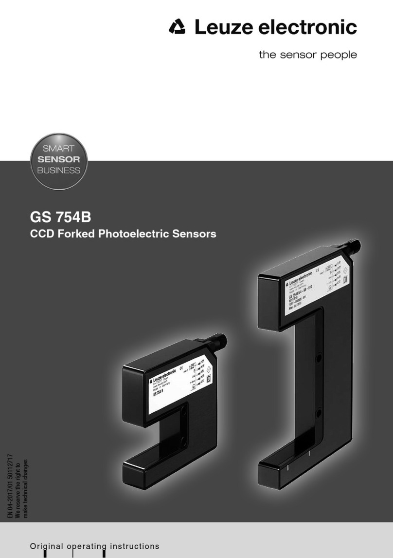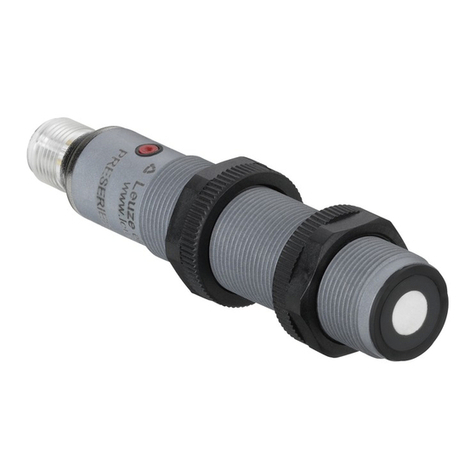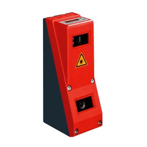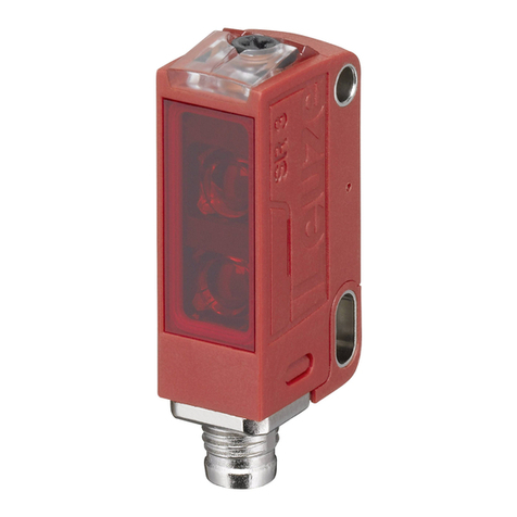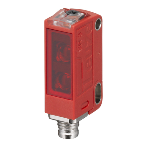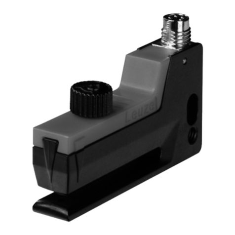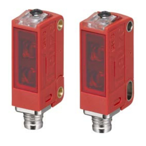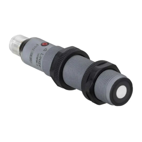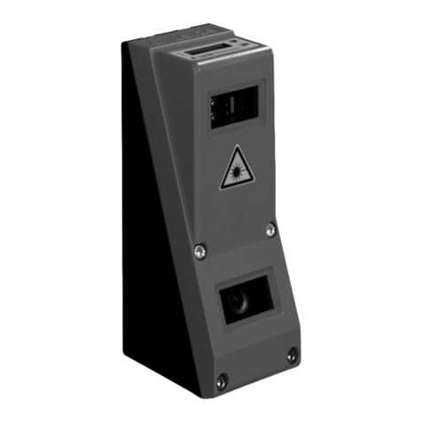
HTU318-300…-M12 - 01 2017/02
HTU318-1200…-M12 - 01
Technical data
Ultrasonic specifications HTU318-300/…-M12 HTU318-1200/…-M12
Scanning range 1)
1) At 20°C
40 … 300mm 2)
2) Target: 100mm x 100mm plate
80 … 1200mm 2)
Adjustment range 40 … 300mm 80 … 1200mm
Ultrasonic frequency 300kHz 200kHz
Typ. opening angle 7° ± 2° 8° ± 2°
Resolution <2mm <2mm
Direction of beam Axial Axial
Reproducibility ± 0.5% 1) 3)
3) From end value
±0.5%
1) 3)
Switching hysteresis 1% 3) 1%
3)
Temperature drift ≤5% 4)
4) Over the temperature range -20°C … +70°C
≤5% 4)
Timing
Switching frequency 8Hz 5Hz
Response time 62ms 100ms
Readiness delay < 100ms < 100ms
Electrical data
Operating voltage UB 5)
5) For UL applications: use is permitted exclusively in Class 2 circuits according to NEC
10 … 30V DC (incl. ± 5% residual ripple)
Residual ripple ±5% of UB
Open-circuit current ≤35mA
Switching output …/4…
…/2…
1 PNP transistor switching output
1 NPN transistor switching output
Function NO (normally open), preset
Output current Max. 150mA
Switching range adjustment 1-point teach: teach-in (pin 2) 2 … 7s to UB,
2-point teach: teach-in (pin 2) 7 … 12s to UB
Changeover
NO/NC
Teach-in (pin 2) > 12s to UB
Indicators
Yellow LED OUT1: object detected
Yellow LED, flashing Teach-in
Green and yellow LEDs flashing Teaching error
Green LED Object within the scanning range
Mechanical data
Housing Plastic (PBT)
Active surface Epoxy resin, glass fiber reinforced
Weight 65g
Ultrasonic transducer Piezoceramic 6)
6) The ceramic material of the ultrasonic transducer contains lead zirconium titanate (PZT)
Connection type M12 connector, 4-pin
Fitting position Any
Environmental data
Ambient temp. (operation/storage) -20° … +70°C/-20° … +70°C
Protective circuit 7)
7) 1=short-circuit and overload protection, 2=polarity reversal protection, 3=wire break and inductive protection
1, 2, 3
VDE protection class III
Degree of protection IP 67
Standards applied EN 60947-5-2
Certifications UL 508, CSA C22.2 No.14-13 5) 8)
8) These proximity switches shall be used with UL Listed Cable assemblies rated 30V, 0.5A min,
in the field installation, or equivalent (categories: CYJV/CYJV7 or PVVA/PVVA7)
Diagrams
HTU318-300/…-M12
HTU318-1200/…-M12
Notes
Observe intended use!
This product is not a safety sensor
and is not intended as personnel
protection.
The product may only be put into
operation by competent persons.
Only use the product in accor-
dance with its intended use.
-100
-50
0
50
100
0 50 100 150 200 250 300 350
y1
y2
Object distance x [mm]
Width y of the sound cone [mm]
Typ. response behavior (plate 100x100mm)
-100
-50
0
50
100
0 50 100 150 200 250 300 350
y1
y2
Object distance x [mm]
Width y of the sound cone [mm]
Typ. response behavior (rod Ø 25mm)
-200
-100
0
100
200
0 200 400 600 800 140012001000
y1
y2
Object distance x [mm]
Width y of the sound cone [mm]
Typ. response behavior (plate 100x100mm)
-200
-100
0
100
200
0 200 400 600 800 140012001000
y1
y2
Object distance x [mm]
Width y of the sound cone [mm]
Typ. response behavior (rod Ø 25mm)
Object distance [mm]
Target (fixed):
plate or rod
Sound cone
= f (α,x)
HTU318
