SICHERHEITS-LICHTSCHRANKEN-SETS MLDSET-M1
UND MLDSET-M2
MLDSET-M1 AND MLDSET-M2 LIGHT BEAM
SAFETY DEVICE SETS
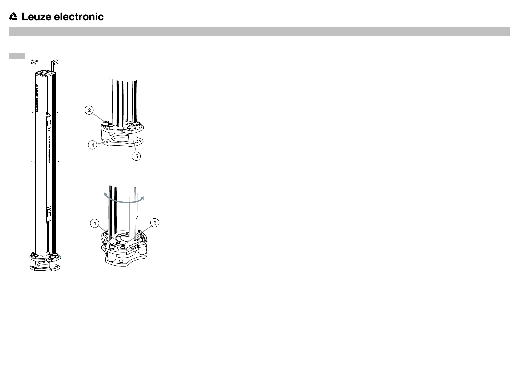
6. Muting-Sensor-Sets ausrichten und in Betrieb nehmen
A: Positionieren Sie die Sensoren bzw. Reflektoren.
Lösen Sie die Kanalabdeckung (4) und die Inbusschraube
(5).
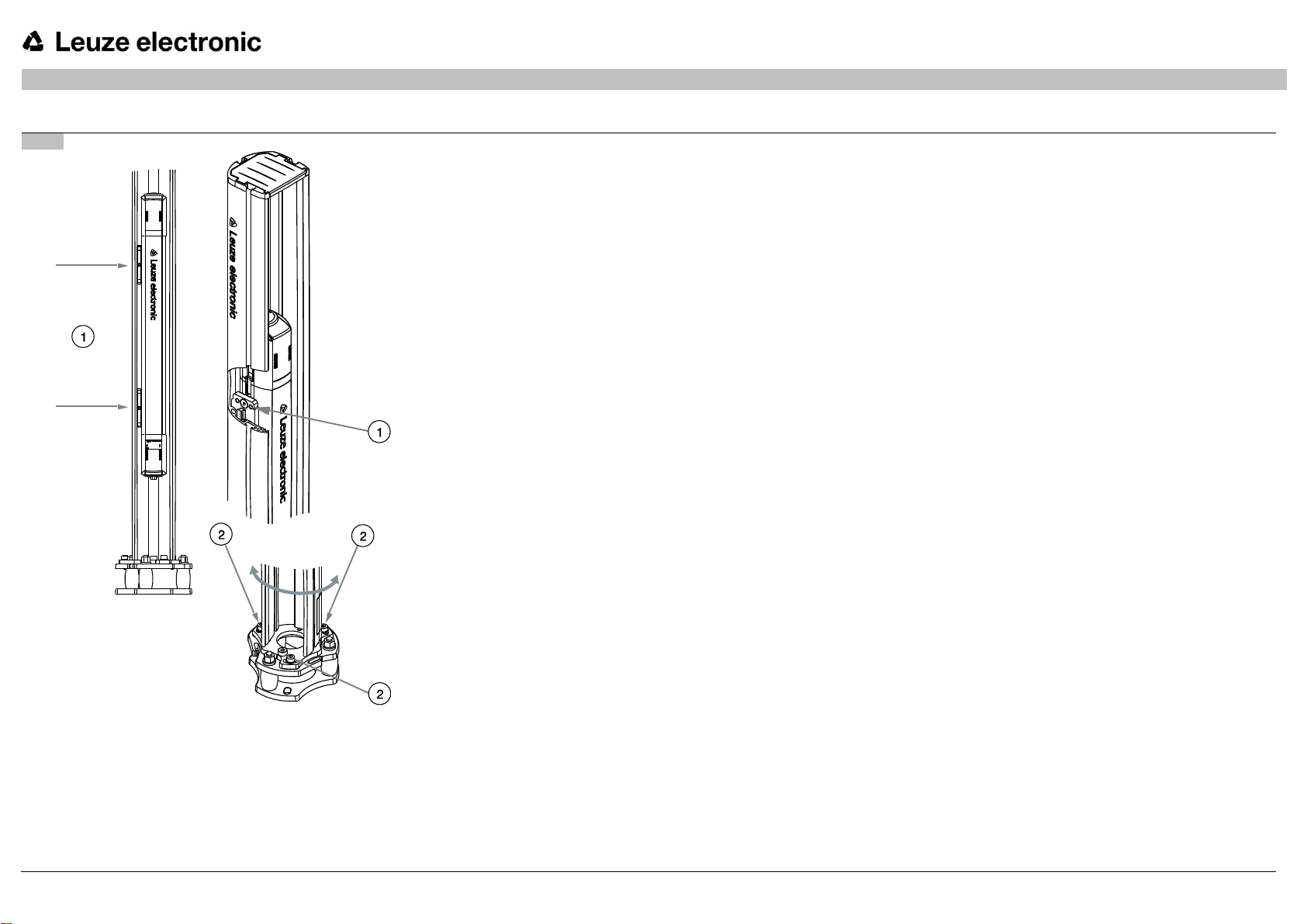
Positionieren Sie Sensoren bzw. Reflektoren durch
Verschieben in Achsrichtung (6).
Ziehen Sie die Inbusschraube nach dem Ausrichten wieder
fest (5).
Schneiden Sie die Kanalabdeckung passend zurecht und
setzen Sie sie wieder ein (4).
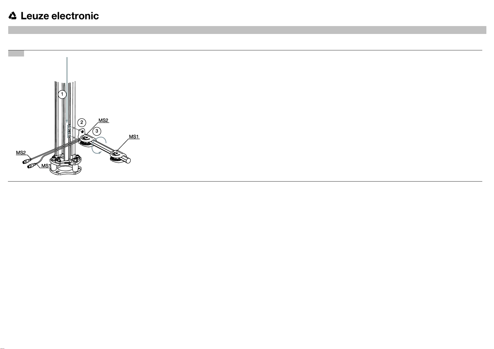
B: Richten Sie die Sensoren und Reflektoren aus.
Lösen Sie die beiden Kreuzschlitzschrauben (7).
Stellen Sie den korrekten Winkel der Sensoren bzw.
Reflektoren durch Drehen ein (8).
Ziehen Sie die Kreuzschlitzschrauben nach dem Ausrichten
fest (7).
Die optimale Ausrichtung ist erreicht, wenn die grünen
LEDs der Muting-Sensoren leuchten!
6. Align and start up Muting Sensor Sets
A: Position the sensors/reflectors.
Loosen the duct cover (4) and the Allen screw (5).
Position the sensors/reflectors by moving in the axial
direction (6).
After aligning, retighten the Allen screw (5).
Cut the duct cover to the appropriate length and
remount (4).
B: Align the sensors and reflectors.
Loosen the two Phillips screws (7).
Turn to set the correct angle of the sensors/reflectors
(8).
After aligning, retighten the Phillips screws (7).
The optimal alignment has been achieved when the
green LEDs on the muting sensors illuminate!
7. Checkliste – Vor der ersten Inbetriebnahme bearbeiten
Nehmen Sie die Maschine oder Anlage nach den
Anweisungen der Original Betriebsanleitung des
Sicherheits-Sensors in Betrieb.
7. Edit Checklist – before the initial start-up
Start up the machine or system according to the
original operating instructions of the safety sensor.