manuals.online logo
Brands
  1. Home
  2. •
  3. Brands
  4. •
  5. Leviton
  6. •
  7. Controllers
  8. •
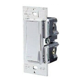
  9. Leviton DECORA NE515 User manual

Leviton DECORA NE515 User manual

For Technical Assistance Call:
1-800-824-3005 (U.S.A. Only)
www.leviton.com
LIMITED 5 YEAR WARRANTY AND EXCLUSIONS
Leviton warrants to the original consumer purchaser and not
for the benefit of anyone else that this product at the time of
its sale by Leviton is free of defects in materials and
workmanship under normal and proper use for five years from
the purchase date. Leviton’s only obligation is to correct such
defects by repair or replacement, at its option, if within such
five year period the product is returned prepaid, with proof of
purchase date, and a description of the problem to Leviton
Manufacturing Co., Inc., Att: Quality Assurance
Department, 59-25 Little Neck Parkway, Little Neck, New
York 11362-2591. This warranty excludes and there is
disclaimed liability for labor for removal of this product or
reinstallation. This warranty is void if this product is installed
improperly or in an improper environment, overloaded,
misused, opened, abused, or altered in any manner, or is
not used under normal operating conditions or not in
accordance with any labels or instructions. There are no
other or implied warranties of any kind, including
merchantability and fitness for a particular purpose, but
if any implied warranty is required by the applicable
jurisdiction, the duration of any such implied warranty,
including merchantability and fitness for a particular purpose,
is limited to five years. Leviton is not liable for incidental,
indirect, special, or consequential damages, including
without limitation, damage to, or loss of use of, any
equipment, lost sales or profits or delay or failure to
perform this warranty obligation. The remedies provided
herein are the exclusive remedies under this warranty,
whether based on contract, tort or otherwise.
DI-000-NE515-00A
Partition Controller
Cat. No. NE515
24VDC
24mA, 0.6W
For use w/compatible Leviton LCnet products
For more information go to
www.leviton.com/D3200
INSTALLATION INSTRUCTIONS
DI-000-NE515-00A
RESET
1
2
3
4
A
A
A
A
Figure 1
Partition Controller Function Buttons
FEATURES
•Leviton’s Decora®Style design • Gangable with 1 additional unit for selection of up to 256 configurations
•Each NE515 can call up to 16 configurations • Fits standard wall box
•Low-Voltage for easy installation
INTRODUCTION
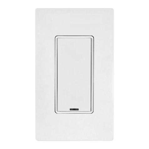
The Partition Controller, Cat No. NE515, is a Decora-style device that sends commands to control combine/separate features. This allows changes of partition configurations with
a touch of a button. The unit provides a unique, entry pad interface that matches Decora® style devices. The NE515 is ideal when lighting rooms with movable walls using the
D3200 Systems.
DESCRIPTION
The NE515 allows you to manipulate lighting in a room with up to four movable walls. Each button will place each D3208 Multizone Controller into the proper configuration when a
wall is present or removed. After programming of D3208(s)/D3206(s) and connection to the NE515 is complete, the NE515 buttons 1 through 4 will be illuminated to indicate
configuration 1 (all walls removed). Pressing a button on the NE515 will turn OFF the NE515 LED associated with that button and will illuminate the Reset button indicating a wall
is present and a different lighting configuration has been implemented. Pressing the Reset button will return the system back into configuration 1 (which will illuminate buttons 1
through 4 of the NE515 to show all walls are removed).
The NE515 in conjunction with a D3208 system can be used more generally as a configuration controller where movable walls may not be utilized.
FCC COMPLIANCE STATEMENT
This device complies with part 15 of the FCC Rules. Operation is subject to the following two conditions: (1) This device must not cause harmful interference, and (2) This device
must accept any interference received, including interference that may cause undesired operation.
INSTALLATION INSTRUCTIONS
WARNING: TO BE INSTALLED AND/OR USED IN ACCORDANCE WITH APPROPRIATE ELECTRICAL CODES AND REGULATIONS.
WARNING: IF YOU ARE NOT SURE ABOUT ANY PART OF THESE INSTRUCTIONS, CONSULT A QUALIFIED ELECTRICIAN.
CAUTION: DISCONNECT POWER WHEN SERVICING FIXTURE OR CHANGING LAMPS.
CAUTION: THE PARTITION CONTROLLER OPERATES OFF OF LOW-VOLTAGE (24VDC), SO CARE MUST BE TAKEN WHEN REPLACING A LIGHT SWITCH. CONSULT
LOCAL BUILDING CODES AND REGULATIONS FOR PROPER LOW-VOLTAGE INSTALLATION.
TO INSTALL:
1. WARNING: TO AVOID FIRE, SHOCK, OR DEATH; TURN OFF POWER AT CIRCUIT BREAKER OR FUSE AND TEST THAT POWER IS OFF BEFORE WIRING!
2. Low-Voltage Wiring: Connect per appropriate WIRING DIAGRAM as follows: Insert each lead into appropriate Plug connector location by pushing firmly (refer to Wiring
Diagrams 1 and 2). If using stranded wire, twist strands of each lead tightly (making sure that there are no stray strands) and push firmly into appropriate Plug connector
location.
NOTES:
•LCnet must be wired using a twisted pair for the CAN_H and CAN_L wires. Leviton recommends using CAT5 wire.
•If the device is the first or last one on the bus, the LCnet must be terminated. Use the terminating plug (included) making sure to connect shorting wire to CAN_H or you
may also short the center terminal in the connector on the device to the CAN_H terminal (refer to Wiring Diagrams 1 and 2).
3. Tighten the screws on the Plug connector making sure that no bare conductor shows. Connect Plug connector to Jack on the back of the Controller.
4. Carefully position all wires to provide room in outlet box for Controller. Mount Controller into box with mounting screws supplied.
5. Replace wallplate as follows:
•Remove "A" tab when using standard Decora® wallplate (refer to Figure 1).
•Leave “A” tabs intact when using Decora® Screwless wallplate.
6. Restore power at circuit breaker or fuse. INSTALLATION IS COMPLETE.
TO OPERATE
1. At the desired D3208 Controller, use the programming wizards to enter the Configuration wizard and access the Comb/Separate menu.
NOTE: Refer to Controller instruction sheet for programming details.
2. Using the UP/DOWN arrows, pick which walls you wish to be present out of the eight available walls. When selected,
the NE515 will shut OFF the LED(s) of the button(s) corresponding to the wall(s) that you have just entered.
NOTE: The walls can also be chosen by entering a configuration number.
3. Assign all attributes to the D3208 Controllers in the system under this configuration to combine the groups of the now joined D3200.
4. With this configuration set, you can move on to set up all configurations needed.
When you want to change configurations corresponding to a wall being removed or added, simply press the button on the NE515. This will cause the corresponding NE515
button to toggle states (LED ON/OFF) and signal a change in configuration. The Reset button may also toggle state.
NOTES:
•When using a NE515 Partition Controller, each button corresponds to its identical space, i.e. button 1 on the NE515 corresponds to space one in the combine/separate function.
•When first installed, the default configuration is #1 which corresponds to all D3208’s in a common group. The D3208’s will be all combined for one large area and the NE515
will have all buttons except for the reset button lit.
•The device will internally assign a configuration number based on the Configuration Matrix on page 2.:
Use , v or SEL
>Comb/Separate
V
Use , v or SEL
<CONFIG WIZARD>
V
SEL PARTITIONS:
>________<
GND (Green)
GND
Not Used
Not Used
+24V DC (Green/White)
+24V DC
CAN-L (Blue/White)
CAN-L
CAN-H (Blue)
CAN-H
LCnet
Back of Partition Controller
GND (Green)
GND
Not Used
Not Used
+24V DC (Green/White)
+24V DC
CAN-L (Blue/White)
CAN-L
CAN-H (Blue)
CAN-H
GND (Green) GND
Not Used Not Used
+24V DC (Green/White) +24V DC
CAN-L (Blue/White) CAN-L
CAN-H (Blue) CAN-H
LCnet
Back of Partition Controller Back of Partition Controller
Wiring Diagram 2 - Two Location Application
Wiring Diagram 1 - Single Station Application
WALL CONFIGURATION EXAMPLES (REFER TO FIGURE AND CONFIGURATION MATRIX )
NOTE: The symbols (____, 1___, 11__, 1__1, etc.) shown in the Configuration Matrix are representative of what may be displayed on the SEL PARTITIONS: menu
of the D3208. For example “Wall Addition/Removal (First 4 locations as displayed on SEL PARTITIONS menu of D3208).”
To operate (one button pushed):
When the wall is removed to make a bigger room, the button corresponding to the wall in place is pressed, changing the configuration to the one programmed by the
user signifying the combining of the desired D3208’s (refer to the “TO OPERATE” section).
Button Lit Config. Wall Removed Controllers in common group (when configuration is programmed by user):
Button 1 2 Wall 1 A + B is separated from C, which is
separated from D, which is separated from E.
Button 2 3 Wall 2 A is separated from B + C, which is
separated from D, which is separated from E.
Button 3 5 Wall 3 A is separated from, B which is separated
from, C + D which is separated from E.
Button 4 9 Wall 4 A is separated from B which is separated
from C which is separated from D + E.
To operate (multiple buttons pushed):
Button Lit Config. Walls removed Controllers in common group (when
configuration is programmed by user):
Button 1 + 2 4 Wall 1 + Wall 2 A + B + C is separated from D which is separated from E.
Button 2 + 3 7 Wall 2 + Wall 3 A is separated from B + C + D which is separated from E.
PROGRAMMING
When combining two NE515s in a system you now have the ability to manipulate lighting in a room with four movable walls. One of the NE515s can be used to
control walls 1-4 and the other NE515 can be used to control walls 5-8. The default setting is the first 4 walls.
To switch and control the last 4 walls, proceed as follows:
1. Press and hold top and bottom (Reset) button on NE515 for 5 seconds. All LED’s will blink to indicate the unit is in programming mode.
2. Go to the D3208 in the system and select the Comb/Separate menu in the Configuration Wizard.
3. Choose wall 8 to be placed and press the Select button.
4. The NE515 will illuminate the second to last bottom button (Button 4) to indicate that wall 8 has been chosen.
5. The NE515 now controls walls 5-8.
6. To re-program back to walls 1-4, go to Steps 1-3 and choose wall 1 instead of wall 8 in Step 3.
1
AB C D E
234
MOVABLE WALL
MOVABLE WALL
MOVABLE WALL
MOVABLE WALL
D320X D320X D320X D320X D320X
DI-000-NE515-00A
____ l___ _l__ ll__ __l_ l_l_ _ll_ lll_ ___l l__l _l_l ll_l __ll l_ll _lll llll
12 34 5 6 7 8 9 101112 13 1415 16
17 18 19 20 21 22 23 24 25 26 27 28 29 30 31 32
33 34 35 36 37 38 39 40 41 42 43 44 45 46 47 48
49 50 51 52 53 54 55 56 57 58 59 60 61 62 63 64
65 66 67 68 69 70 71 72 73 74 75 76 77 78 79 80
81 82 83 84 85 86 87 88 89 90 91 92 93 94 95 96
97 98 99 100 101 102 103 104 105 106 107 108 109 110 111 112
113 114 115 116 117 118 119 120 121 122 123 124 125 126 127 128
129 130 131 132 133 134 135 136 137 138 139 140 141 142 143 144
145 146 147 148 149 150 151 152 153 154 155 156 157 158 159 160
161 162 163 164 165 166 167 168 169 170 171 172 173 174 175 176
177 178 179 180 181 182 183 184 185 186 187 188 189 190 191 192
193 194 195 196 197 198 199 200 201 202 203 204 205 206 207 208
209 210 211 212 213 214 215 216 217 218 219 220 221 222 223 224
225 226 227 228 229 230 231 232 233 234 235 236 237 238 239 240
241 242 243 244 245 246 247 248 249 250 251 252 253 254 255 256
I___
_I__
II__
__I_
I_I_
_II_
III_
___I
I__I
_I_I
II_I
__II
I_II
_III
IIII
____
Wall Addition/Removal (First 4 locations)
Wall Addition/Removal (Last 4 locations)
CONFIGURATION MATRIX
TROUBLESHOOTING
•If NO LED’s are lit; there is no power
- Check wiring.
•Communication LED (located under face of device) does NOT light when the button is pressed
- Check power wiring connections.
•Unable to change configurations (add/remove walls) as expected
- Check setup of configurations in D3208.
For Multiple Power Packs on the Bus:
•The Controller has power (at least the OFF LED is ON) but pressing the buttons have no effect on the lights; there is no
communication between the Controller and the Power Pack
- If the communication LED does NOT flash when a button is pressed, see above.
- If the communication LED does flash, check the address of the Power Pack and Controller (refer to Dimming Power Pack
Instructions).
Terminating Plug
CAN-H
Middle Terminal
LCnet
Termination
LCnet
Termination
Terminating Plug
CAN-H
Middle Terminal

Other Leviton Controllers manuals

Leviton Decora NE505 User manual

Leviton

Leviton Decora NE505 User manual

Leviton ILLUMATECH INF05-1L User manual

Leviton

Leviton ILLUMATECH INF05-1L User manual

Leviton MLC16 User manual

Leviton

Leviton MLC16 User manual

Leviton decora smart D24SF User manual

Leviton

Leviton decora smart D24SF User manual

Leviton Decora Illumatech IPF01-1L User manual

Leviton

Leviton Decora Illumatech IPF01-1L User manual

Leviton NorthStar Site Controller User manual

Leviton

Leviton NorthStar Site Controller User manual

Leviton PowerSwitch MS4X-302 User manual

Leviton

Leviton PowerSwitch MS4X-302 User manual

Leviton Decora Smart User manual

Leviton

Leviton Decora Smart User manual

Leviton DECORA ILLUMATECH IPF01-1LX User manual

Leviton

Leviton DECORA ILLUMATECH IPF01-1LX User manual

Leviton vizia rf+ User manual

Leviton

Leviton vizia rf+ User manual

Leviton DECORA SURESLIDE 6627 User manual

Leviton

Leviton DECORA SURESLIDE 6627 User manual

Leviton Lumina LURPC-01W User manual

Leviton

Leviton Lumina LURPC-01W User manual

Leviton DRKDN-U Series User manual

Leviton

Leviton DRKDN-U Series User manual

Leviton RZCZ1 User manual

Leviton

Leviton RZCZ1 User manual

Leviton RZCZ4 User manual

Leviton

Leviton RZCZ4 User manual

Leviton Decora Smart DW15P User manual

Leviton

Leviton Decora Smart DW15P User manual

Leviton Decora IPHS5 Series User manual

Leviton

Leviton Decora IPHS5 Series User manual

Leviton RZCS4 User manual

Leviton

Leviton RZCS4 User manual

Leviton miniZ mZn20-102 User manual

Leviton

Leviton miniZ mZn20-102 User manual

Leviton BITWISE BWBC1 User manual

Leviton

Leviton BITWISE BWBC1 User manual

Leviton 73A00-3ZB Mounting instructions

Leviton

Leviton 73A00-3ZB Mounting instructions

Leviton CN221 User manual

Leviton

Leviton CN221 User manual

Leviton NorthStar Site Controller User manual

Leviton

Leviton NorthStar Site Controller User manual

Leviton Intellect ZLDNK User manual

Leviton

Leviton Intellect ZLDNK User manual

Popular Controllers manuals by other brands

Hunter X-CORE quick start guide

Hunter

Hunter X-CORE quick start guide

esera automation ECO 10 user guide

esera automation

esera automation ECO 10 user guide

CYP CDPS-IRL Operation manual

CYP

CYP CDPS-IRL Operation manual

Parker 690+ series product manual

Parker

Parker 690+ series product manual

Rain Bird ESP-7ME3 Advanced user's manual

Rain Bird

Rain Bird ESP-7ME3 Advanced user's manual

Tosot XE7A-24/H owner's manual

Tosot

Tosot XE7A-24/H owner's manual

AMS Controls XL100 BATTERY REPLACEMENT GUIDE

AMS Controls

AMS Controls XL100 BATTERY REPLACEMENT GUIDE

Bogart Engineering SC-2030 Technical manual

Bogart Engineering

Bogart Engineering SC-2030 Technical manual

Darco ERO-32MN-1 instruction manual

Darco

Darco ERO-32MN-1 instruction manual

Mitsubishi Electric MELSEC iQ-F Series manual

Mitsubishi Electric

Mitsubishi Electric MELSEC iQ-F Series manual

Mitsubishi Electric FX3G SERIES user manual

Mitsubishi Electric

Mitsubishi Electric FX3G SERIES user manual

TestEquity F4T user guide

TestEquity

TestEquity F4T user guide

Siemens Climatix POL822 Mounting instructions

Siemens

Siemens Climatix POL822 Mounting instructions

YASKAWA MP2600iec Hardware manual

YASKAWA

YASKAWA MP2600iec Hardware manual

Erreka ROLL 60C Installation instruction

Erreka

Erreka ROLL 60C Installation instruction

Intermec 9180 Getting started guide

Intermec

Intermec 9180 Getting started guide

Emerson Bettis RTS Service manual

Emerson

Emerson Bettis RTS Service manual

Vega VEGATOR 131 operating instructions

Vega

Vega VEGATOR 131 operating instructions

manuals.online logo
manuals.online logoBrands
  • About & Mission
  • Contact us
  • Privacy Policy
  • Terms and Conditions

Copyright 2025 Manuals.Online. All Rights Reserved.