manuals.online logo
Brands
  1. Home
  2. •
  3. Brands
  4. •
  5. Leviton
  6. •
  7. Controllers
  8. •
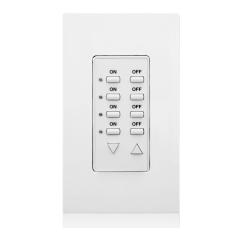
  9. Leviton DECORA 661F Series User manual

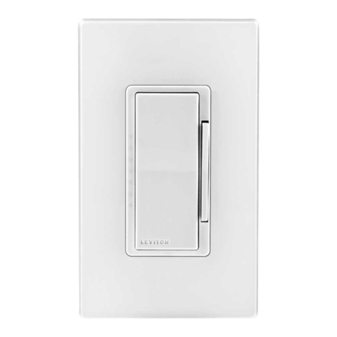
Leviton DECORA 661F Series User manual

Identifying your wiring application
(most common):
WARNING: If the wiring in the wall box does not resemble any
of these configurations, consult an electrician.
QUIET FAN SPEED CONTROL
Single Pole or 3-Way
Cat. No. 661F – Ceiling Fan 1.5A
120VAC, 60Hz
INSTALLATION INSTRUCTIONS
Step 3
Step 2
ONOFF
ONOFF
ONOFF
ONOFF
ONOFF
ONOFF
ONOFFONOFF
ONOFF
ONOFF
ONOFF
ONOFF
WARNING: TO AVOID FIRE, SHOCK, OR DEATH; TURN
OFF POWER at circuit breaker or fuse and test that power is
off before wiring or servicing fixture!
Step 1
Single Pole
1. Line (Hot)
2. Neutral
3. Ground
4. Load
NOTE: For 3-Way applications, note that one of the screw terminals from
the old switch being removed will usually be a different color (Black) or
labeled Common. Tag that wire with electrical tape and identify as the
common (Line or Load) in both the Fan Speed Control wall box and 3-way
switch wall box.
Preparing and connecting wires:
Strip gage
Cut
(if necessary)
5/8"
• Make sure that the ends of the wires from the
wall box are straight (cut if necessary).
• Remove 5/8" (1.6 cm) of insulation from each
wire in the wall box (shown).
•For Single-Pole Application, go to Step 4a.
• For 3-Way Application, go to Step 4b.
Single-Pole Wiring Application:
Step 4a
3-Way
1. Line or Load (See note below)
2. Neutral
3. Ground
4. First Traveler – note color
5. Second Traveler – note color
DI-000-0661F-02A
3
2
4
1
5
3
21
4
Cap with
Wire Connector Green
Ground
BlackRed
Red
Hot (Black)
Neutral (white)
Line
120VAC, 60Hz
Fan Speed Control
NOTE: There is NO derating
necessary for multi-gang
installations of this Fan
Speed Control.
Tools needed to install your Fan Speed Control
Installing your Fan Speed Control
Slotted/Philips Screwdriver Electrical Tape Ruler
Pliers Pencil Cutters
Installing Control by itself or with other devices
Connect wires per WIRING DIAGRAM as follows:
• Green or bare copper wire in wall box to GREEN control lead.
• Line Hot wall box wire to BLACK control lead.
• Load wall box wire to RED control lead.
• Remaining RED control lead should have a label affixed.
DO NOT REMOVE this label in a single pole application.
NOTE: If the insulating label is not affixed to the second RED lead
use electrical tape or a wire connector to cover.
Proceed to Step 5.
Red
Black
Neutral
Green Ground
Red
This wire is used in 3-way installations only.
For single pole installations,
do not remove this insulating label.
Insert wires
straight
then twist
clockwise
Electrical Tape
instructions or rating label on the motor to confirm type. Use with any other types of motors or equipment may cause
overheating and/or damage to the motors or equipment.
• Use only one (1) Fan Speed Control per load. The switch(es) will turn ON the fan at the speed level selected at the control.
• To avoid overheating and possible damage to this device and other equipment, DO NOT install to control a receptacle,
fluorescent lighting, a motor or a transformer-operated appliance other than appropriate ceiling fans
.
• If you are unsure about any part of these instructions, consult an electrician.
• Use this device with copper or copper clad wire only.
WARNINGS:
• TO AVOID FIRE, SHOCK, OR DEATH: TURN OFF POWER at circuit breaker or fuse and test that power is off
before wiring or servicing fixture!
• TO AVOID FIRE, SHOCK, OR DEATH: this control is to be used with ceiling fans that are rated 120VAC, total load
1.5 amperes maximum.
• Use and/or install in accordance with appropriate electrical codes and regulations.
CAUTIONS:
•For use on ceiling paddle fans with split-capacitor or shaded pole motors only. Please refer to manufacturer’s
© 2018 Leviton Mfg. Co., Inc.
Restore Power:
Restore power at circuit breaker or fuse.
Installation is complete.
Step 7
For Technical Assistance Call: 1-800-824-3005 (U.S.A. Only) www.leviton.com
• Fan does not turn ON
- Circuit breaker or fuse has tripped.
- Fan has burned out.
- Fan Neutral connection is not wired.
3-Way Wiring Application:
Step 4b Fan Speed Control Mounting:
WARNING: TO AVOID FIRE, SHOCK, OR DEATH; TURN
OFF POWER at circuit breaker or fuse and test that power is off
before wiring or servicing fixture!
Step 6
Installation may now be completed
by carefully positioning all wires
to provide room in wall box for the
control. Mount the control into box
with mounting screws supplied.
Attach wallplate.
ON:
Push rocker switch "ON"
OFF:
Push rocker switch "OFF"
CHANGING SPEEDS:
Move slide bar
- Fan will change speeds.
Testing your Fan Speed Control prior to
mounting in the wall box:
Step 5
NOTE: If using the control in a 3-way application, the control will turn
ON at the speed level set on the control's slide bar. The fan can be
controlled from either the control or the switch location.
DI-000-0661F-02A
LIMITED 5 YEAR WARRANTY AND EXCLUSIONS
Leviton warrants to the original consumer purchaser and not for the benefit of anyone else that this product at the time of its sale by Leviton is free of defects in materials and workmanship under normal and proper use for five years from the purchase date. Leviton’s only obligation is to correct
such defects by repair or replacement, at its option. For details visit www.leviton.com or call 1-800-824-3005. This warranty excludes and there is disclaimed liability for labor for removal of this product or reinstallation. This warranty is void if this product is installed improperly or in an
improperenvironment,overloaded,misused,opened,abused,oralteredinanymanner,orisnotusedundernormaloperatingconditionsornotinaccordancewithanylabelsorinstructions.Therearenootherorimpliedwarrantiesofanykind,includingmerchantabilityand fitness for
aparticular purpose, butifanyimpliedwarrantyisrequiredby the applicable jurisdiction, the duration of anysuchimpliedwarranty,includingmerchantabilityandfitnessfor a particular purpose, is limited to fiveyears.Levitonisnot liable forincidental,indirect,special,orconsequential
damages,includingwithout limitation,damageto,or lossofuse of,anyequipment,lost salesorprofitsordelayorfailure toperformthiswarrantyobligation.Theremedies providedhereinare theexclusiveremediesunderthiswarranty,whetherbasedoncontract,tort orotherwise.
FOR CANADA ONLY
For warranty information and/or product returns, residents of Canada should
contact Leviton in writing at Leviton Manufacturing of Canada Ltd to the
attention of the Quality Assurance Department, 165 Hymus Blvd, Pointe-
Claire (Quebec), Canada H9R 1E9 or by telephone at 1 800 405-5320.
Slide bar
to vary
the speed
of the fan
Push
ON/OFF
Connect wires per WIRING DIAGRAM as follows:
• Green or bare copper wire in wall box to GREEN control lead.
• Common (Line hot or Load) wire to BLACK control lead.
• Remove insulating label and connect the first traveler wire to the RED
control lead.
• Connect the second traveler wire to the remaining RED control lead.
Proceed to Step 5.
Operation
Troubleshooting
• Restore power at circuit breaker
or fuse.
• Carefully holding control as
shown, slide control lever to
highest position. If fan is not ON,
press rocker. Fan should turn
ON to highest speed level.
If fan does not turn ON, refer
to the TROUBLESHOOTING
section.
Black
Tag
Red
Neutral
Ground
Green
Red
Insert wires
straight
then twist
clockwise
Electrical Tape
Green
Ground
BlackRed
Hot (Black)
Neutral (white)
Line
120V
AC, 60Hz
Red
Black Screw
(common)
3-Way Switch Fan Speed Control
ARTWORK PRINT SPECIFICATIONS
DIMENSIONS / FOLD SCHEME / BINDERY DIAGRAM
PART NUMBER REV DESCRIPTION
Line Screen:
Angle:
Resolution:
Offset Flexo
Other
Body Material:
Bindery
Thickness:
Trim
Perfect Bind
Die cut Saddle Stitch
Drill
Fold
The information in this document is the exclusive PROPRIETARY property of LEVITON MANUFACTURING COMPANY, INC. It is disclosed
with the understanding that acceptance or review by the recipient constitutes an undertaking by the recipient. (1) to hold this information in strict
confidence, and (2) not to disclose, duplicate, copy, modify or use the information for any purpose other than that for which disclosed.
PlantApprovals:
PN-ARN: Pilot Rev:ECR Number:
Released Artwork Format: Production PDF Artwork Release Date:
Artwork Print Specification Sheet Rev A12.eps
PMCQA
Artist:
Notes:
Other
Cust Other
S & A
Mktg Eng
FOR LEVITON USE ONLY
SPECIFICATIONS :
PROCESS :
MANUAL INTERIORS / BINDERY / FOLD SCHEME :
COMMENTS :
For manuals - designates cover specifications
Material:
Thickness:
Finish:
:
Artwork must be printed at 100% (1:1 scale)
Spot
CMYK
1:
4:
3:
2:
Color(s): over
1:
4:
3:
2:
Fonts:
Spot
CMYK
1:
4:
3:
2:
Color(s): over
1:
4:
3:
2:
Fonts:
Fold Line
Die Cut Punch/Drill Hole
Glue
Kiss Cut Cellophane
Fold Line
Perforate
Die Cut
Die Line Key:
DI-000-0661F-02A
40 Lbs
Black
1 1
X
Helvetica
Instruction Sheet
X
X
X
D. Quiles
HD0118-5330
J. Tang
cc: H. Cai
08
E. Krajci
V. LoNigro
K. Cohen
cc: B. Randall
F. Tse
cc: J. Lowe
C. Buttitta
5/21/18
X
X
X
X
X
8.5"
11"
Part No.
FINAL
4.25"
2.75"
Part No.
X1

This manual suits for next models

6

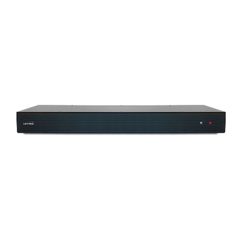
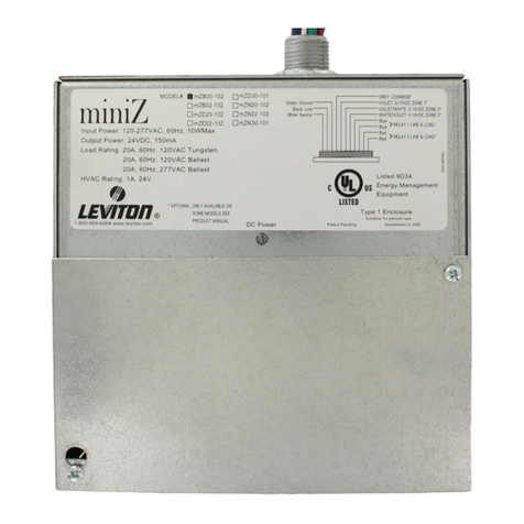
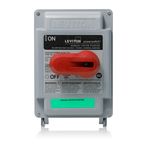
Other Leviton Controllers manuals

Leviton DRC Smart Pack User manual

Leviton

Leviton DRC Smart Pack User manual

Leviton RTD01-10 User manual

Leviton

Leviton RTD01-10 User manual

Leviton D3208 User guide

Leviton

Leviton D3208 User guide

Leviton Intellect ZL07S-N00 User manual

Leviton

Leviton Intellect ZL07S-N00 User manual

Leviton Decora NE515 User manual

Leviton

Leviton Decora NE515 User manual

Leviton Decora NE505 User manual

Leviton

Leviton Decora NE505 User manual

Leviton Decora Home Controls 16450 User manual

Leviton

Leviton Decora Home Controls 16450 User manual

Leviton DECORA NE515 User manual

Leviton

Leviton DECORA NE515 User manual

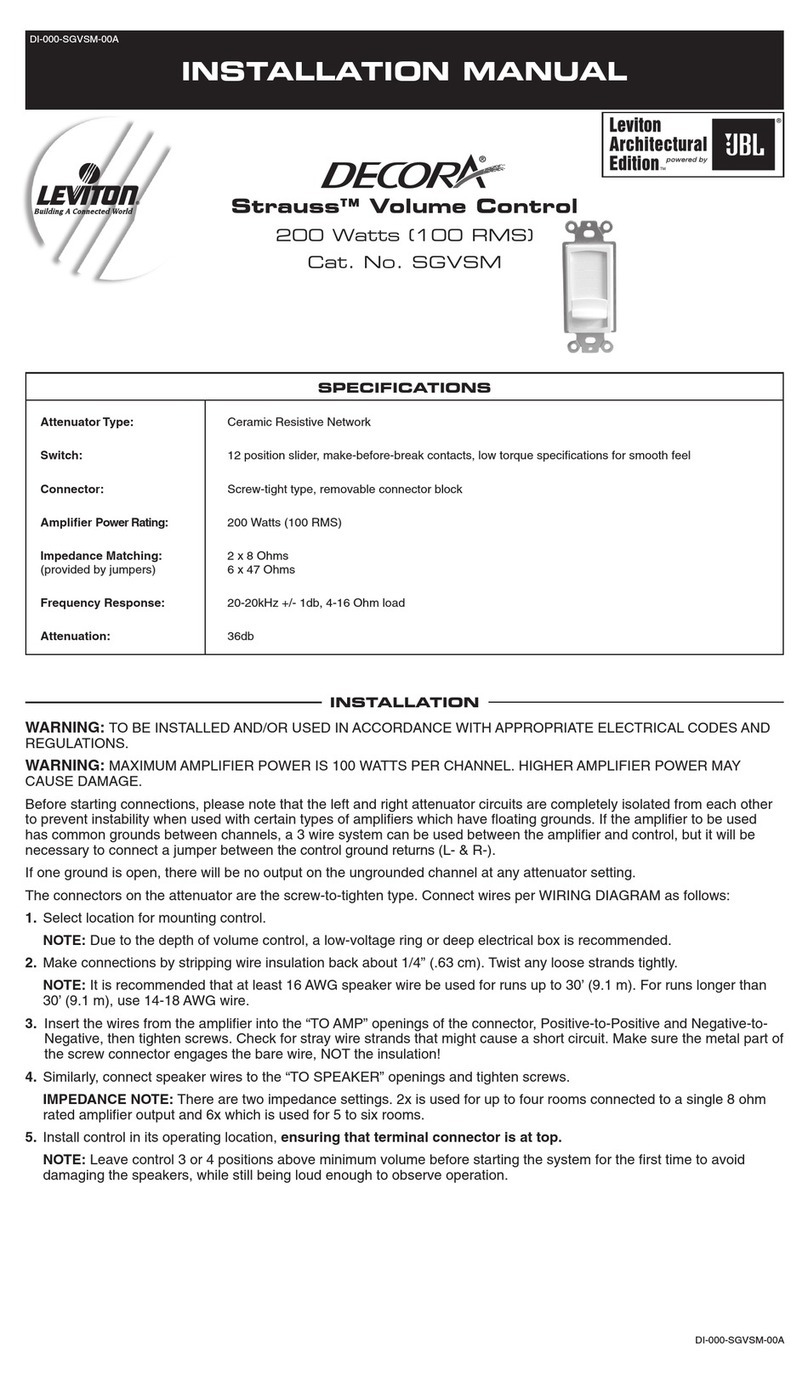
Leviton SGVSM-00W User instructions

Leviton

Leviton SGVSM-00W User instructions

Leviton 6616 User manual

Leviton

Leviton 6616 User manual

Leviton vizia rf+ User manual

Leviton

Leviton vizia rf+ User manual

Leviton ILLUMATECH INF05-1L User manual

Leviton

Leviton ILLUMATECH INF05-1L User manual

Leviton CN221 User manual

Leviton

Leviton CN221 User manual

Leviton BITWISE BWBC1 User manual

Leviton

Leviton BITWISE BWBC1 User manual

Leviton Decora Illumatech IPF01-1L User manual

Leviton

Leviton Decora Illumatech IPF01-1L User manual

Leviton SGVSM-00W User manual

Leviton

Leviton SGVSM-00W User manual

Leviton LE-RZCZ Installation instructions

Leviton

Leviton LE-RZCZ Installation instructions

Leviton MS602-BW User manual

Leviton

Leviton MS602-BW User manual

Leviton CN200 User manual

Leviton

Leviton CN200 User manual

Leviton NorthStar Site Controller User manual

Leviton

Leviton NorthStar Site Controller User manual

Leviton Decora IPHS5 Series User manual

Leviton

Leviton Decora IPHS5 Series User manual

Leviton Lumina RF Decora DL057-D0Z User manual

Leviton

Leviton Lumina RF Decora DL057-D0Z User manual

Leviton HCPRF Manual

Leviton

Leviton HCPRF Manual

Leviton GreenMAX DRC User manual

Leviton

Leviton GreenMAX DRC User manual

Popular Controllers manuals by other brands

JNGE Power JN-MPPT user manual

JNGE Power

JNGE Power JN-MPPT user manual

MULTISPAN OC 99 operating manual

MULTISPAN

MULTISPAN OC 99 operating manual

Genasun GV-4 Operator's manual

Genasun

Genasun GV-4 Operator's manual

warmth R8C.963 instructions

warmth

warmth R8C.963 instructions

Comunello RAMPART 1000 Installation and user manual

Comunello

Comunello RAMPART 1000 Installation and user manual

Sunricher SR-2820B Installation

Sunricher

Sunricher SR-2820B Installation

Curtis Instruments PMC 1200 Series manual

Curtis Instruments

Curtis Instruments PMC 1200 Series manual

Niko 310-01800 manual

Niko

Niko 310-01800 manual

Omron SYSMAC CS/CJ Series Programming manual

Omron

Omron SYSMAC CS/CJ Series Programming manual

resideo Buoy BSV-101-WC10-LF Homeowner quick start guide

resideo

resideo Buoy BSV-101-WC10-LF Homeowner quick start guide

Texas Instruments TMS320DM644x user guide

Texas Instruments

Texas Instruments TMS320DM644x user guide

Dings DS-OLS8-FRS4 Technical manual

Dings

Dings DS-OLS8-FRS4 Technical manual

MR tapcon 240 Quick reference guide

MR

MR tapcon 240 Quick reference guide

industrie technik evolution AHU-XXXSX1 series user manual

industrie technik

industrie technik evolution AHU-XXXSX1 series user manual

Branson Emerson Ultrasplice 40 operating manual

Branson

Branson Emerson Ultrasplice 40 operating manual

Kaidi KDH139 user manual

Kaidi

Kaidi KDH139 user manual

Nexo NX242 user manual

Nexo

Nexo NX242 user manual

Orca Blinky Pro user manual

Orca

Orca Blinky Pro user manual

manuals.online logo
manuals.online logoBrands
  • About & Mission
  • Contact us
  • Privacy Policy
  • Terms and Conditions

Copyright 2025 Manuals.Online. All Rights Reserved.