manuals.online logo
Brands
  1. Home
  2. •
  3. Brands
  4. •
  5. Leviton
  6. •
  7. Controllers
  8. •
  9. Leviton HXC10 User manual

Leviton HXC10 User manual

For Technical Assistance Call:
1-800-824-3005
www.leviton.com
LIMITED FIVE YEAR WARRANTY AND EXCLUSIONS
Leviton warrants to the original consumer purchaser and not for
the benefit of anyone else that this product at the time of its sale by
Leviton is free of defects in materials and workmanship under
normal and proper use for five years from the purchase date.
Leviton’s only obligation is to correct such defects by repair or
replacement,atitsoption,ifwithin such five year periodthe product
is returned prepaid, with proof of purchase date, and a description
of the problem to Leviton Manufacturing Co., Inc., Att: Quality
Assurance Department, 59-25 Little Neck Parkway, Little
Neck, New York 11362-2591. This warranty excludes and there
is disclaimed liability for labor for removal of this product or
reinstallation. This warranty is void if this product is installed
improperly or in an improper environment, overloaded, misused,
opened, abused, or altered in any manner, or is not used under
normal operating conditions or not in accordance with any labels
or instructions. There are no other or implied warranties of any
kind, including merchantability and fitness of a particular purpose,
but if any implied warranty is required by the applicable
jurisdiction, the duration of any such implied warranty, including
merchantability and fitness for a particular purpose, is limited to
five years. Leviton is not liable for incidental, indirect, special, or
consequential damages, including without limitation, damage to,
or loss of use of, any equipment, lost sales or profits or delay or
failure to perform this warranty obligation. Theremediesprovided
herein are the exclusive remedies under this warranty, whether
based on contract, tort or otherwise.
FEATURES
• Leviton's Decora® Style design • Memory retained after Power Interruption
• Universal design works with 1 and 2-Way Receivers • Color conversion available
INTRODUCTION
Leviton Residential Powerline Carrier Components are designed to provide the greatest signal integrity and noise immunity
possible. However, in some environments intense electrical noise can cause interference with the signal. Leviton has developed
hardware and techniques for overcoming this interference when properly applied.
LEVITON’S DHC DEVICES FEATURE INTELLISENSE, THE RIGHT TYPE OF AUTOMATIC GAIN CONTROL (AGC)
Leviton DHC devices use Intellisense, a special gated-type of AGC, to help eliminate noise problems (refer Figure 1). This circuit
feature is ideal for powerline carrier systems because it only operates during the signal window when receivers listen for command
signals. Noise levels in the signal window are never as high as they are during other portions of the AC power curve. Therefore,
Leviton’s Intellisense gatedAGC will desensitize a receiver to noise signals with only a minimal reduction in command signal
sensitivity. The result: Problems from noise interference are dramatically reduced without affecting overall system performance.
It is the responsibility of the specifier/installer to test for signal strength and the presence of noise using Leviton test equipment,
Cat. Nos. 6385 (Signal Test Transmitter) and 6386 (Signal Strength Indicator), and to properly apply signal coupling and noise
reduction equipment according to the guidelines provided in the Decora®Home Controls (DHC) Technical Manual and the DHC
Troubleshooting Guide.
Leviton specifically denies any warranty of performance, stated or implied, where electrical noise interference exists at the time of
installation, or subsequent to installation by the addition of noise-producing devices or equipment, or where these components
have been installed for non-residential applications. Installation of a Repeater/Coupler is recommended in all DHC systems.
DHC Components are for residential use only. Installation for any other application voids any warranty, stated or implied.
DESCRIPTION
Wall box Transmitter
The HXCxx is a signal transmitter that works in conjunction with DHC receivers. The Wall-Mounted DHC Transmitter is designed to
provide manual control of loads from one or more locations in a home over standard 60Hz 120V wiring.
The HXCxx Transmitter Body incorporates Leviton’s exclusive Intellisense™ Automatic Gain Control (AGC) circuitry to deliver
clearer and stronger line signals without affecting signals simultaneously on the line from other transmitters. The resulting
performance reliability exceeds that of any other powerline carrier home automation product line available today.
FCC COMPLIANCE STATEMENT
This equipment has been tested and found to comply with the limits for a Class B digital device, pursuant to Part 15 of the FCC
rules. These limits are designed to provide reasonable protection against harmful interference in a residential installation. This
equipment generates, uses, and can radiate radio frequency energy and, if not installed and used in accordance with the
instructions, may cause harmful interference to radio communications. However, there is no guarantee that interference will not
occur in a particular installation. If this equipment does cause harmful interference to radio or television reception, which can be
determined by turning the equipment OFF and ON, the user is encouraged to try to correct the interference by one or more of the
following measures:
• Reorient or relocate the receiving antenna.
• Increase the separation between the equipment and the receiver.
• Connect the equipment into an outlet on a circuit different from that to which the receiver is connected.
• Consult the dealer or an experienced radio/tv Technician for help.
SPECIFICATIONS
Rating: 120VAC, 60Hz
Max. Controllers on 1 circuit: 4
Power Consumption: 3W
HXCxx CONFIGURATIONS
HXC1
Ø
: 1 address, ON/OFF, (1 rocker)
HXC1A: 1 address, ALL ON/ ALLOFF, (1 rocker) - All in House Code
HXC1D: 1 address, ON/OFF, (1 rocker), DIM/BRIGHTEN (inner rocker)
NOTE: Cat. No. HXCxx Wall Mounted Controller is not intended to replace standard wall switches. The Controller requires one
HOT (BLACK), one NEUTRAL (WHITE) conductor and proper grounding for proper operation. Incorrect installation will void warranty.
INSTALLATION INSTRUCTIONS
WARNING: TO BE INSTALLED AND/OR USED IN ACCORDANCE WITH APPROPRIATE ELECTRICAL CODESAND
REGULATIONS.
WARNING: IF YOU ARE NOT SURE ABOUT ANY PART OF THESE INSTRUCTIONS, CONSULT A QUALIFIED
ELECTRICIAN.
WARNING: INSTALLTO CONTROL SCENE DIMMERS AND APPLICABLE DHC RECEIVERS ONLY. DO NOT INSTALL TO
CONTROL ANY LOAD DIRECTLY.
CAUTION: USE THIS DEVICE ONLY WITH COPPER OR COPPER CLAD WIRE. WITHALUMINUM WIRE USE ONLY
DEVICES MARKED CO/ALR OR CU/AL.
TO INSTALL:
1. WARNING: TO AVOID FIRE, SHOCK, OR DEATH; TURN OFF POWER AT CIRCUIT BREAKER OR FUSEAND TEST THAT
POWER IS OFF BEFORE WIRING!
2. Remove approximately 5/8" (1.6 cm) of insulation from circuit conductors.
Command Signal
is picked up Gated AGC ignores
High noise levels
outside signal window
Noise is not
picked up
Signal Window Signal Window Receiver sensitivity
with Intellisense
gated AGC
Figure 2 - Control Functions
PK-93027-10-00-0C
WALL MOUNTED CONTROLLER
w/ Single Addressing
Cat. Nos.
HXC1
Ø
HXC1A
HXC1D
120VAC, 60 Hz
INSTALLATION INSTRUCTIONS
Figure 1 - Intellisense AGC
Figure 3 - Indicator Position Diagram
Cat. No. HXC1D
Unit Code
HXC1
Ø
& -HXC1D config.
House Code
HXC1
Ø
, HXC1A
& HXC1D config.
AE
MI
15
13 9
Large
Upper
Rocker Small
Upper
Rocker
Small
Lower
Rocker
ON/OFF
LED
Large
Lower
Rocker
Mounting Strap
Side Sections
(Cat. No. HXC1D)
Upper
Rocker
ON/OFF
LED
Lower
Rocker
Mounting Strap
Side Sections
(Cat. No. HXC1
Ø
and HXC1A)
PK-93027-10-00-0C
3. Connect wires per appropriate WIRING DIAGRAM as follows: BLACK (Hot) wire to BLACK lead of device, and WHITE (Neutral) to
White lead of device. Twist strands of each lead tightly together and, with circuit conductor, push firmly into appropriate wire
connector. Screw connector on clockwise making sure that no bare wire shows below the connector. Secure each wire connector
with electrical tape.
4. Remove Front Face of Cat. No. HXCxx (refer to Color Conversion Procedure) to access Control Wheels.
5. Using a small screwdriver (included), set the Number Code and Letter Code dials to the desired address by gently turning the
indicators to the proper positions (refer to Figure 3 and the examples in the Testing section).
NOTE: The HXC1A is only equipped with a housecode dial (refer to Figure 3).
6. Mount Cat. No. HXCxx in wall box using the screws provided.
NOTE: If mounted ina multi-gang box, one or more of the side sections may have to be removed. Use pliers to carefully bend side
sections back and forth until they break off (refer to Figure 2).
7. Replace Front Face (refer Color Conversion Procedure).
8. Mount wallplate.
9. Restore power at circuit breaker or fuse. INSTALLATION IS COMPLETE.
COLOR CONVERSION PROCEDURE
The color of this device can be changed to suit your interior design requirements. Simply obtain a color conversion kit of the
appropriate color from your Leviton distributor and proceed as follows (please note that the wallplate must be removed).
1. Select the color of the face you desire.
2. The frame has snaps on its sides. Using a small screwdriver, gently remove the frame from the strap (refer Figure 4).
3. Take the new frame and position it properly to the strap. Line up the plastic snaps with the square holes in the strap. Insert the
snaps on one side of the frame into the strap.
4. Firmly press sideways and down to slip the other snaps into place. The frame snaps in with a audible click. Ensure that all four
snaps are secure. Replace Decora®wallplate. The color conversion is complete.
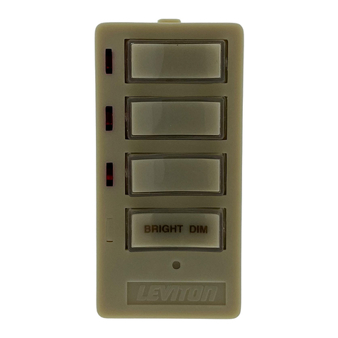
TO OPERATE (Cat. Nos. HXC1
Ø
, HXC1A and HXC1D)
Pressing the upper half of the large rocker will transmit ON and ALL ON commands (Cat Nos. HXC1
Ø
, HXC1A and HXC1D).
Pressing the bottom half of the large rocker will transmit OFF and ALL OFF commands (Cat Nos. HXC1
Ø
, HXC1A and
HXC1D). Pressing the upper half of the small rocker will transmit the BRIGHT command (Cat No. HXC1D). Pressing the bottom
half of the small rocker will transmit the DIM command (Cat No. HXC1D).
When transmitting an ON/ALL ON command, the LED will blink while the signal is being transmitted and will stay ON when the
signal has completed the transmission. When transmitting an OFF/ALL OFF command, the LED will blink while the signal is being
transmitted and turn OFF when the signal has completed the transmission. If there is a BRIGHT/DIM function on the keypad,
pressing the BRIGHT or DIM button will cause the LED on the face of the keypad to flash and will remain flashing until the button is
released.
NOTE: When used with a 2-Way Receivers, the LED's will indicate the status of those devices (i.e., if the Dimmer is turned ON at
it's source, the ON/OFF LED on the Transmitter will turn ON).
TESTING
Press the keypad to confirm that the load or loads are turned ON and OFF within two seconds of signal transmission. If the
Cat. No. HXCxx Controller appears to be functioning improperly or operates erratically, read the following paragraphs, then refer to
the Perfect Performance Checklist.
An ALL ON/OFF (Cat. No. HXC1A) controls all DHC modules set to the same letter code as on the Cat. No. HXCxx Controller. ALL
ON ONLY turns ON lighting modules.ALL OFF turns OFF ALL modules set to the same letter code.
PERFECT PERFORMANCE CHECKLIST
If the Cat. No. HXCxx Controller appears to be functioning improperly proceed with the following steps:
1. Confirm that the Controller is wired exactly as shown in the wiring diagram.
2. Confirm that the receiver module is being supplied from a 120V, 60Hz AC source ONLY.
3. Confirm that the load being controlled is in proper working order. Local switch, ON (check for burned-out bulbs, etc.).
4. Confirm that the Controller is powered and is set to transmit commands to the same letter and number code on receiver modules.
5. Confirm that the Cat. No. HXCxx keypad is installed properly.
NOTE: If the Controller still does not operate properly after following steps 1-5, proceed with diagnostic steps 6 and 7.
6. Set the Controller to transmit address P1. Using a Cat No. 6386 Signal Strength Indicator plugged in on the same branch circuit
as the Controller, confirm that the Controller is transmitting a minimum reading of 2 volts of command signal at the HI-RANGE
setting. If the signal strength is less than 2 volts, have the Controller checked.
7. Check for adequate command signal at the Cat. No. HXCxx location as follows:
A. Plug the Cat. No. 6385 Signal Test Transmitter into a receptacle on the same circuit as the Controller.
B. Using the Cat. No. 6386 Signal Strength Indicator at the HXCxx location, check the command signal amplitude. Signal
strength must be 100mV minimum. If there is less than 100mV of signal present, it may be necessary to couple both legs of
the 120/240 Volt power service at the entrance panel using a Leviton Repeater/Coupler.
C. If the Yellow ERROR CONDITION indicator is lit, there is electrical “noise”present on the AC line which is interfering with
proper module operation. The source of the noise must be identified and either filtered out or eliminated (See Technical
Manual).
8. Installation of a Coupler/Repeater is recommended in all DHC installations for maximum signal.
9. The Leviton Technical Manual covers common DHC problems and system issues in more detail.
Frame
Strap
Snaps
Push in 2 Locations
ON/OFF
LED
Figure 4 - Switch Plate Removal
(Color Conversion Only)
Wiring Diagram 1
Cat. Nos. HXC1
Ø
& HXC1A
PK-93027-10-00-0C
Hot (Black)
Neutral (White)
Controller
Black
White
Line
120VAC, 60Hz
Green
Ground
Hot (Black)
Neutral (White)
Controller
Black
White
Line
120VAC, 60Hz
Green
Ground
Wiring Diagram 2
Cat. No. HXC1D
Frame
Strap
Snaps
Push in 2 Locations ON/OFF
LED
Cat. Nos. HXC1
Ø
& HXC1A Cat. No. HXC1D

This manual suits for next models

2

Other Leviton Controllers manuals

Leviton DECORA SURESLIDE 6627 User manual

Leviton

Leviton DECORA SURESLIDE 6627 User manual

Leviton MLC128R User manual

Leviton

Leviton MLC128R User manual

Leviton NorthStar Site Controller User manual

Leviton

Leviton NorthStar Site Controller User manual

Leviton DRKDN-U Series User manual

Leviton

Leviton DRKDN-U Series User manual

Leviton ILLUMATECH INF05-1L User manual

Leviton

Leviton ILLUMATECH INF05-1L User manual

Leviton Lumina RF Decora DL057-D0Z User manual

Leviton

Leviton Lumina RF Decora DL057-D0Z User manual

Leviton DL057-D0Z User manual

Leviton

Leviton DL057-D0Z User manual

Leviton PowerSwitch MS4X-302 User manual

Leviton

Leviton PowerSwitch MS4X-302 User manual

Leviton CN220 User manual

Leviton

Leviton CN220 User manual

Leviton Decora Illumatech IPF05-1L User manual

Leviton

Leviton Decora Illumatech IPF05-1L User manual

Leviton DECORA ILLUMATECH IPF01-1LX User manual

Leviton

Leviton DECORA ILLUMATECH IPF01-1LX User manual

Leviton DECORA 661F Series User manual

Leviton

Leviton DECORA 661F Series User manual

Leviton miniZ mZn20-102 User manual

Leviton

Leviton miniZ mZn20-102 User manual

Leviton intellect ZL057-D0Z User manual

Leviton

Leviton intellect ZL057-D0Z User manual

Leviton RZCZ1 User manual

Leviton

Leviton RZCZ1 User manual

Leviton MS302 User manual

Leviton

Leviton MS302 User manual

Leviton vizia rf+ User manual

Leviton

Leviton vizia rf+ User manual

Leviton MLC128R User manual

Leviton

Leviton MLC128R User manual

Leviton MLC16 User manual

Leviton

Leviton MLC16 User manual

Leviton HXC4D-1TW Installation instructions

Leviton

Leviton HXC4D-1TW Installation instructions

Leviton ILLUMATECH IPE04-1L User manual

Leviton

Leviton ILLUMATECH IPE04-1L User manual

Leviton INI06-10 User manual

Leviton

Leviton INI06-10 User manual

Leviton DRC Smart Pack User manual

Leviton

Leviton DRC Smart Pack User manual

Leviton MC7008 User manual

Leviton

Leviton MC7008 User manual

Popular Controllers manuals by other brands

MULTISPAN PID 2303-1C-M1 Installation guidelines

MULTISPAN

MULTISPAN PID 2303-1C-M1 Installation guidelines

PEDAL COMMANDER PC17-BT installation manual

PEDAL COMMANDER

PEDAL COMMANDER PC17-BT installation manual

Baker Hughes Mooney 21 Series instruction manual

Baker Hughes

Baker Hughes Mooney 21 Series instruction manual

Evco EV3 HP Installer manual

Evco

Evco EV3 HP Installer manual

Mira Excel Installation & user guide

Mira

Mira Excel Installation & user guide

Siemens SIMOTION C230-2 Equipment manual

Siemens

Siemens SIMOTION C230-2 Equipment manual

HomePro ZTH200 user manual

HomePro

HomePro ZTH200 user manual

Aqua Computer farbwerk 360 User and installation manual

Aqua Computer

Aqua Computer farbwerk 360 User and installation manual

MultiTrode MultiSmart Installation & operation manual

MultiTrode

MultiTrode MultiSmart Installation & operation manual

Klimor HMI Compact Operation and maintenance manual

Klimor

Klimor HMI Compact Operation and maintenance manual

Innotech M2K04 User instructions

Innotech

Innotech M2K04 User instructions

Nitek VR448 Operation manual

Nitek

Nitek VR448 Operation manual

Siemens SIMATIC S7-200 manual

Siemens

Siemens SIMATIC S7-200 manual

Eaton xComfort CSEZ-01/07 Assembly instructions

Eaton

Eaton xComfort CSEZ-01/07 Assembly instructions

Mitsubishi Electric R60AD8-G user manual

Mitsubishi Electric

Mitsubishi Electric R60AD8-G user manual

Pixsys ATR226 user manual

Pixsys

Pixsys ATR226 user manual

Crestron DigitalMedia 8G+ DM-RMC-200-C Do guide

Crestron

Crestron DigitalMedia 8G+ DM-RMC-200-C Do guide

Pelican 9460 manual

Pelican

Pelican 9460 manual

manuals.online logo
manuals.online logoBrands
  • About & Mission
  • Contact us
  • Privacy Policy
  • Terms and Conditions

Copyright 2025 Manuals.Online. All Rights Reserved.