manuals.online logo
Brands
  1. Home
  2. •
  3. Brands
  4. •
  5. Leviton
  6. •
  7. Controllers
  8. •
  9. Leviton Decora Illumatech IPF05-1L User manual

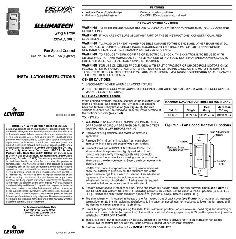
Leviton Decora Illumatech IPF05-1L User manual

Single Pole (One location) or 3-Way (Multi-location)
Fan Speed Control
120VAC, 60Hz
Cat. No. IPF
Ø
5-1L, 5A (Lighted)
INSTALLATION INSTRUCTIONS
DI-000-IPF05-02B
Tools needed to install your Fan Speed Control:
Slotted/Philips Screwdriver Electrical Tape
Pliers Pencil
Cutters Ruler
Changing the color of your Fan Speed Control:
Your Fan Speed Control includes two color options. The Control ships with
the White frame attached. To change color of frame, proceed as follows:
Move the slider up or down one full cycle to automatically engage the
slider control mechanism.
Installing Fan Speed Control by itself or with other
devices:
If installing Control in a single device application, proceed with the
INSTALLING YOUR FAN SPEED CONTROL section. If installing
Control in a multi-device application, proceed as follows:
MULTI-DEVICE APPLICATION:
NOTE: You only need to remove side sections if installing with other
controls or if it does not fit in wall box – not when installing with
mechanical switches.
When installing more than one Fan Speed Control in the same
location, the side sections of the mounting strap must be removed.
Use pliers to carefully bend side sections back and forth until they
break off. The side sections dissipate heat, so removing them requires
a derating of the control's capacity (refer to chart).
INSTALLING YOUR FAN SPEED CONTROL
NOTE: Use check boxes when Steps are completed.
WARNING: To avoid fire, shock, or death; TURN OFF
POWER at circuit breaker or fuse and test that power is off
before wiring!
Removing existing switch: Remove existing
wallplate and switch mounting screws. Carefully pull switch
from wall box. DO NOT remove wires attached to the switch
at this time.
Identifying your wiring application (most
common):
NOTE: If the wiring in the wall box does not resemble any of
these configurations, consult a qualified electrician.
Step 2
Step 4
Step 1
ONOFF
ONOFF
ONOFF
ONOFF
ONOFF
ONOFF
ONOFFONOFF
ONOFF
ONOFF
ONOFF
ONOFF
Single-Pole:
Look at the back of your switch.
If there are 2 wires connected to
two screw terminals (not
including a green or bare copper
wire used for grounding), you
have a Single-Pole switch.
Step 3
con’t
3-Way:
Look at the back of your switch.
If there are 3 wires connected to
three screw terminals (not including
a green or bare copper wire used
for grounding), you have a 3-Way
switch. Note that one of the
screw terminals will usually be a
different color (black) or labeled
Common. Tag that wire with
electrical tape to identify.
Tag Common
Screw Wire
Push in side at tab
to release Line up tabs and
press in side to
attach
WARNINGS AND CAUTIONS:
•To be installed and/or used in accordance with appropriate electrical codes and regulations.
•If you are unsure about any part of these instructions, consult a qualified electrician.
•To avoid overheating and possible damage to this device and other equipment, do not install to
control a receptacle, fluorescent lighting, a motor- or a transformer-operated appliance other than
appropriate ceiling fans.
•To reduce the risk of fire or electrical shock, this control is to be used with ceiling fans that are marked
as suitable for use with a solid-state fan speed control and is rated 120VAC, total load 5 amperes maximum.
WARNINGS AND CAUTIONS:
•For use on ceiling paddle fans with split-capacitor or shaded pole motors only. Please refer to
manufacture's instructions or rating label on the motor to confirm type. Use with any other types of
motors or equipment may cause overheating and/or damge to the motors or equipment.
•Use only one (1) Fan Speed Control per load. The switch(es) will turn ON the fan at the speed level
selected at the control.
•Disconnect power at circuit breaker or fuse when servicing fixture.
•Use this device only with copper or copper clad wire. With aluminum wire use only devices marked
CO/ALR or CU/AL.
Bend back and
forth to remove side
section
Remove
all inner
side
sections
Do not
remove
outer
side
sections
•Disconnect wires from screw terminals or
Quickwire™ slots (shown).
•Pull off pre-cut insulation from Control leads.
•Make sure that the ends of the wires from the
wall box are
straight (cut if necessary)
.
•Remove 5/8" (1.6 cm) of insulation from each
wire in the wall box (shown).
•For Single-Pole Application, go to Step 5A.
•For 3-Way Application, go to Step 5B.
Strip 5/8"
Cut
(if necessary)
Press in slot and
pull out wire Strip Gage
5/8"
√
Step 3
Disconnecting switch wires and preparing wires:
More than
Cat. No. Single Two Devices 2 Devices
IPF
Ø
5-1L 600W, 5A 500W, 4.1A 400W, 3.3A
MAXIMUM LOAD PER DIMMER FOR MULTI-DEVICE
Single-Pole Wiring Application:
Connect wires per WIRING DIAGRAM as follows:
Screw wire nuts on clockwise making sure no bare conductors
show below the wire connectors. Secure each connector with
electrical tape.
NOTE: Control can be installed on either the Load or Line side.
•Green control Ground lead to Green or bare copper
wire in wall box.
•Black control lead to any wall box wire removed
from old switch.
•Red control lead without insulating label to remaining
wall box wire. Proceed to Step 6.
•Remaining Red control lead should have Red insulation
label affixed. Proceed to Step 6.
NOTE: If insulating label is not affixed to Red lead, use a
small wire nut or electrical tape to cap off. Proceed to Step 6.
3-Way Wiring Application:
LIMITED 2 YEAR WARRANTY AND EXCLUSIONS
Leviton warrants to the original consumer purchaser and not for the benefit of anyone else that this product at the time of its sale by Leviton is free of defects in materials and workmanship under normal and proper use for two years from the purchase date. Leviton’s only obligation
is to correct such defects by repair or replacement, at its option, if within such two year period the product is returned prepaid, with proof of purchase date, and a description of the problem to Leviton Manufacturing Co., Inc., Att: Quality Assurance Department, 59-25 Little
Neck Parkway, Little Neck, New York 11362-2591. This warranty excludes and there is disclaimed liability for labor for removal of this product or reinstallation. This warranty is void if this product is installed improperly or in an improper environment, overloaded, misused, opened,
abused, or altered in any manner, or is not used under normal operating conditions or not in accordance with any labels or instructions. There are no other or implied warranties of any kind, including merchantability and fitness for a particular purpose, but if any implied warranty is
required by the applicable jurisdiction, the duration of any such implied warranty, including merchantability and fitness for a particular purpose, is limited to two years. Leviton is not liable for incidental, indirect, special, or consequential damages, including without limitation, damage
to, or loss of use of, any equipment, lost sales or profits or delay or failure to perform this warranty obligation. The remedies provided herein are the exclusive remedies under this warranty, whether based on contract, tort or otherwise.
Connect wires per WIRING DIAGRAM as follows:
Screw wire nuts on clockwise making sure no bare
conductors show below the wire connectors. Secure each
connector with electrical tape.
NOTE: Control can be installed on either the Load or Line side.
•Green control Ground lead to Green or bare copper wire
in wall box.
•Black control lead to tagged (common) wall box wire
identified when removing old switch.
•Remove Red insulating label from Red lead.
•Any Red control lead to any of the remaining
wall box wires.
•Remaining Red control lead to remaining wall box wire.
Testing your Fan Speed Control prior to
mounting in wall box:
Minimum Fan Speed Adjustment:
Fan Speed Control Mounting:
TURN OFF POWER AT CIRCUIT BREAKER OR FUSE.
Step 7
Restore Power: Restore power at circuit breaker or
fuse. Installation is complete.
OPERATION
NOTE: The indicator light will illuminate when the control is in the
OFF position to facilitate access in the dark.
NOTE: If using the control in a 3-way application, the control will
turn ON at the speed level set on the control's slide control lever.
The fan can be controlled from either the control or the
switch location.
TROUBLESHOOTING
•Fan does not turn ON and ON/OFF LED does not turn ON
- Circuit breaker or fuse has tripped.
- Fan has burned out.
- Fan Neutral connection is not wired.
NOTE: If further information is needed in identifying the HOT wire
in a 3-Way application, go to
Leviton's website at www.leviton.com.
For non-standard wiring applications, refer
to Wire Nut and Connector Size Chart
DI-000-IPF05-02B
Step 5b
Hot (Black)
Neutral (White)
Fan
Fan Speed Control 3-Way Switch
Red
Black
Green
Ground
Green
Ground
Black
White
Red
Line
120VAC, 60Hz
Common
Terminal
(Black Screw)
Step 6
Step 5a
Hot (Black)
Neutral (White)
Fan
Fan Speed Control
Black
Green
Ground
Black
White
Red
Line
120VAC, 60Hz
Red
Insulating
Label
Step 9
WIRE CONNECTOR / # OF COND.
COMBINATION CHART
1- #12 w/ 1 to 3 #14, #16 or #18
2- #12 w/ 1 or 2 #16 or #18
1- #14 w/ 1 to 4 #16 or #18
2- #14 w/ 1 to 3 #16 or #18
Black
Red
Neutral
Green
Ground
Red
This wire is used in 3-way installations only.
For single pole installations, do not remove this
insulating label.
Black
Tag
Red
Green
Red
Neutral
Ground
Step 5b
con’t
•Restore power at circuit breaker
or fuse.
•Carefully holding control as
shown, move slider control lever
to highest position. Fan should
turn ON to highest level. If fan
does not turn ON, depress push-
button switch once. Fan should
turn ON to highest level.
If fan still does not turn ON,
refer to the
TROUBLESHOOTING section.
Installation may now be completed
by carefully positioning
all wires to provide room in wall box
for control. Mount control
into box with mounting screws
supplied. Attach wallplate.
ON/OFF:
Depress push-button switch to ON
position - Fan will turn ON at level set
by slider.
Depress push-button switch to OFF
position - Fan will turn OFF.
Fan Speed:
Move slider control lever up or down to
vary the speed of the fan.
Insert wires
straight then twist
clockwise
Insert wires
straight then twist
clockwise
Electrical
Tape
Electrical
Tape
This Fan Speed Control incorporates
a minimum fan speed adjustment
that allows you to set the level of
speed when the slider control lever
is in the lowest position.
Move slider to the lowest position.
Using a small, insulated screwdriver,
rotate the adjustment screw as
shown until the desired level of
minimum speed is obtained. Ensure
that when the push-button is
switched ON, the fan paddles are
rotating.
Step 8
Other Leviton Controllers manuals

Leviton RZCZ1 User manual

Leviton

Leviton RZCZ1 User manual

Leviton N1000-006 User manual

Leviton

Leviton N1000-006 User manual

Leviton MLC128R User manual

Leviton

Leviton MLC128R User manual

Leviton DRKDN-U Series User manual

Leviton

Leviton DRKDN-U Series User manual

Leviton NorthStar Site Controller User manual

Leviton

Leviton NorthStar Site Controller User manual

Leviton DECORA ILLUMATECH IPF01-1LX User manual

Leviton

Leviton DECORA ILLUMATECH IPF01-1LX User manual

Leviton Lumina RF Decora DL057-D0Z User manual

Leviton

Leviton Lumina RF Decora DL057-D0Z User manual

Leviton CN221 User manual

Leviton

Leviton CN221 User manual

Leviton Lumina LURPC-01W User manual

Leviton

Leviton Lumina LURPC-01W User manual

Leviton MS302 User manual

Leviton

Leviton MS302 User manual

Leviton SGVSM-00W User manual

Leviton

Leviton SGVSM-00W User manual

Leviton NorthStar Site Controller User manual

Leviton

Leviton NorthStar Site Controller User manual

Leviton CD250 User manual

Leviton

Leviton CD250 User manual

Leviton NE505 User manual

Leviton

Leviton NE505 User manual

Leviton CN200 User manual

Leviton

Leviton CN200 User manual

Leviton miniZ mZb00-102 User manual

Leviton

Leviton miniZ mZb00-102 User manual

Leviton HXC10 User manual

Leviton

Leviton HXC10 User manual

Leviton LE-RZCZ Installation instructions

Leviton

Leviton LE-RZCZ Installation instructions

Leviton DECORA SURESLIDE 6627 User manual

Leviton

Leviton DECORA SURESLIDE 6627 User manual

Leviton MC7008 User manual

Leviton

Leviton MC7008 User manual

Leviton D4200 User manual

Leviton

Leviton D4200 User manual

Leviton 6616 User manual

Leviton

Leviton 6616 User manual

Leviton Decora NE505 User manual

Leviton

Leviton Decora NE505 User manual

Leviton intellect ZL057-D0Z User manual

Leviton

Leviton intellect ZL057-D0Z User manual

Popular Controllers manuals by other brands

Brightlink BL-VW37-4K operating instructions

Brightlink

Brightlink BL-VW37-4K operating instructions

AirCom RLM operating manual

AirCom

AirCom RLM operating manual

Swagelok RHPS Series user manual

Swagelok

Swagelok RHPS Series user manual

Yoshitake OB-30 manual

Yoshitake

Yoshitake OB-30 manual

AUMA TIGRON TR-M30X Short instructions

AUMA

AUMA TIGRON TR-M30X Short instructions

CDVI Digicode Mifare DGM1D installation manual

CDVI

CDVI Digicode Mifare DGM1D installation manual

Linear ANALOG DEVICES DC1590B Demo Manual

Linear

Linear ANALOG DEVICES DC1590B Demo Manual

Ariston AST 100 Installation, commissioning and user instructions

Ariston

Ariston AST 100 Installation, commissioning and user instructions

VDO ENGINE ACTUATORS - brochure

VDO

VDO ENGINE ACTUATORS - brochure

Banner DXM100 instruction manual

Banner

Banner DXM100 instruction manual

Hoval TopTronic C-SYS operating manual

Hoval

Hoval TopTronic C-SYS operating manual

SIIG USB SoundWave 7.1 Pro Quick installation guide

SIIG

SIIG USB SoundWave 7.1 Pro Quick installation guide

SEW-Eurodrive MOVI-C UHX45A Series manual

SEW-Eurodrive

SEW-Eurodrive MOVI-C UHX45A Series manual

Cissell DX4 CONTROLLER manual

Cissell

Cissell DX4 CONTROLLER manual

Doctorseyes PLC-4 instruction manual

Doctorseyes

Doctorseyes PLC-4 instruction manual

brennenstuhl RC 2044 operating instructions

brennenstuhl

brennenstuhl RC 2044 operating instructions

safgard 250 quick start guide

safgard

safgard 250 quick start guide

Sincro RD1 Operation manual

Sincro

Sincro RD1 Operation manual

manuals.online logo
manuals.online logoBrands
  • About & Mission
  • Contact us
  • Privacy Policy
  • Terms and Conditions

Copyright 2025 Manuals.Online. All Rights Reserved.