manuals.online logo
Brands
  1. Home
  2. •
  3. Brands
  4. •
  5. Leviton
  6. •
  7. Dimmer
  8. •
  9. Leviton i 48e Manual

Leviton i 48e Manual

i Series e Installation Supplement Page 1of 4
LIT-30955-01
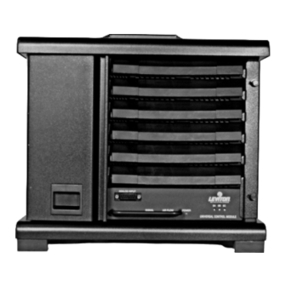
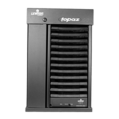
i48eand i96e Dimmer Rack
Installation and Maintenance Manual Supplement
Enclosed is a copy of the Installation and Maintenance Manual for the original product. This
supplement serves as a temporary modifier of that manual for the iSeries e product. Please
follow the instructions in the manual except where modified below.
Page 9, Paragraph 1 –The e Series has two additional control cables that plug into the rear center
of the control module tray. One is a six-pin rectangular connector whose cable routes through
the right wall. The other is a five-pin in-line connector whose cable routes down underneath the
control module tray. Both cables must also be disconnected before removing the control module
tray.
Page 12, Label Part Numbers –The label part numbers for i Series E and the associated
explanation are as follows:
Part Number Rack Type
LBL-31084-00 i96e phase balanced
LBL-31085-00 i96e sequential
LBL-31346-00 i48e phase balanced
LBL-31247-00 i48e sequential
Standard racks are shipped from the factory in the phase balanced configuration. This
places dimmers 1 and 2 at the top of the rack and the top of the phase A bus, dimmers 3
and 4 one-third of the way down the rack at the top of the phase B bus, and dimmers 5
and 6 two-thirds of the way down the rack at the top of the phase C bus. In this
configuration “phase balanced” labels should be selected. If the rack is full of dimmers
you may want to have them arranged sequentially from top to bottom. The rack is easily
configured for this sequential arrangement and the “sequential” labels should be selected.
Page 13, Table 3 –The dimmer module part numbers for e Series dimmer racks must include an
“E” suffix. Constant module part numbers do not require the “E”.
Page 16, Table 4 – The dimmer module part numbers for e Series dimmer racks must include an
“E” suffix.
Page 17, Paragraph 2 –There are no PC Serial control conductors in the e Series. There are,
however, 0 –10VDC Analog inputs.
i Series e Installation Supplement Page 2of 4
LIT-30955-01
Page 17, Figure 16 –SW1 has been replaced with jumpers JP3 and JP4 immediately under TB3
in the e Series. An additional terminal block TB4 has been added immediately to the left of TB1
for the Analog inputs.
Page 17, Last Paragraph –The Network connector is a pair of RJ45 telephone-type connectors.
Page 18, Paragraph 3 –In the e Series DMXO controls only the top control module and DMX1
only the bottom (optional) control module. If it is desired to “pile-on” the two DMX inputs both
control modules must be installed. Both ports support DMX only, CMX is not available with e
Series.
Page 18, Paragraph 4 –SW1 has been replaced with jumpers JP3 and JP4 in e Series. Install the
jumpers for termination and remove the jumpers for no termination.
Page 18, Paragraphs 5 and 6 –CMX is not available with e Series.
Page 20, Paragraph 3 –The PC port is not available with e Series.
Page 21, Section 13.4 –The Network feature has not yet been implemented in e Series.
Page 21 –Add the following:
13.5. Terminal Block 4: 0 –10 VDC Analog Inputs
TB4 is designed to accept the analog control signals from the Remembrance line of
analog control stations. The first twelve terminals numbered from right to left accept 0 –
10 VDC analog signals. Terminal 13 is the common and terminal 14 is the V+ for the
Remembrance station.
Page 22, Tables 8 and 9 –The dimmer module part numbers for e Series dimmer racks must
include an “E” suffix. Constant module part numbers do not require the “E”.
Page 24, Section 18 –Loads connected to the dimmer rack load terminals cannot be tested in e
Series until the control module(s) is installed. Go to Section 20 for control module installation
and then return to this section.
Testing loads is a completely different process in e Series. The process is as follows:
1. Turn off power to the rack. Caution: do not work inside rack while the rack is energized.
2. Remove the top control module and bottom couple of dimmers.
3. Temporarily remove any control wiring from TB1 terminals 3 and 4.
4. Jumper terminals 3 and 4 together on TB1. This will put all dimmers in “panic” mode.
5. Replace modules and turn on power to rack. The green Load LED(s) on each dimmer module
should now be on.
6. Turn on and off the circuit breaker(s) on each dimmer module. The corresponding load should
turn on and off.
7. When testing is complete reverse steps 1 through 5 above to replace control wiring.
Page 25, Section 19 –There are no individual “panic” switches in e Series. Panic selection is
accomplished in software. E Series racks are shipped with all dimming channels programmed
i Series e Installation Supplement Page 3of 4
LIT-30955-01
for “panic” operation in order to facilitate testing. Call Colortran Field Service for further
instructions on how to program the “panic” feature. Observe the second “Caution” notice on
page 25.
Page 27, Paragraph 1 –The part number for the e Series control module is 4-0311E. The same
module is used for both 120V and 230V systems.
Page 27, Paragraph 2 –The e Series control module has no movable handle tabs.
Page 27, Paragraph 4 –In the single-phase mode the Phase B LED will track Phase A in the i96
rack and Phase C in the i48 rack.
Page 27, New Paragraph –Before installation set the “rack” number on the thumbwheel switch
on the front of each control module. Rack 1 will respond to control channels 1 through 96 (i96e)
or 1 through 48 (i48e); rack 2 will respond to control channels 97 through 192 (i96e) or 49
through 96 (i48e); etc. Note: If the rack has been programmed for a custom patch such as when
there is a mixture of single or dual dimmers, or non-dims, set the thumbwheel to “0”.
Page 28 through 34, Sections 21 through 24 –These sections do not apply to e Series.
i Series e Installation Supplement Page 4of 4
LIT-30955-01
Luma
-
Net Termination
Breaker with Fluorescent Breaker Handle Tie
Kit Installed
Luma-Net Control Signal Installation Requirements
For i Series e dimmer racks which require the termination of a Luma-Net control run, follow
these instructions.
Connection
The Luma-Net link connects to the backplane of the rack on
TB1 as follows:
Signal Luma-Net 3
Terminal Rack
Terminal Rack Label
Rem + 19RAKCOM
Rem -210 RAKCOM
overlined
Common 38GND
+V 47+12V
Although most Luma-Net phoenix style connectors have six
terminals, there is no terminal 5 nor terminal 6 connection at the
dimmer rack. Terminal 6 which is used for the hardware lock
feature has no use at the dimmer rack and the “terminate”
feature which is handled by terminal5 is handled by the
termination jumper.
Termination
If the rack is at the end of the run,Jumper JP2 (Rackcom Termin.) must be installed in the
backplane to terminate the run. The jumper is shipped installed by factory default.
Now the dimmer rack is capable of receiving and processing Luma-Net commands.
Special Installation Requirements for HiLume Dimming Circuits
The HILUME feature is only usable in i Series e. This style of
fluorescent dimming ballast requires (3) wires, (1) switched, (1)
dimmed, and (1) neutral. To accommodate these requirements,
the software will couple the odd-numbered dimmer with the
next even-numbered dimmer. The odd-numbered dimmer is the
variable component and the even-numbered dimmer is the
switched component. The breakers for these dimmers must be
tied together with the CTP-4-0307 fluorescent handle-tie kit and
the rack slot labeled. Installation instructions for this are
included with the kit.
The odd/even breakers in the i Series Quad are not below each
other so they cannot be tied together; therefore, HILUME is not a quad feature. When the
HILUME feature couples the dimmers the second address is dropped unless the subsequent
addresses are moved up dimmer by dimmer. For this reason it is a good idea to put the HILUME
dimmers at the end.
Termination Jumper
(Rackcom Termin)

Other Leviton Dimmer manuals

Leviton 06674 User manual

Leviton

Leviton 06674 User manual

Leviton i Series e User manual

Leviton

Leviton i Series e User manual

Leviton Decora Illumatech IPM06-1L User manual

Leviton

Leviton Decora Illumatech IPM06-1L User manual

Leviton Acenti ACE04-1L User manual

Leviton

Leviton Acenti ACE04-1L User manual

Leviton Decora Mural MDE03-1 User manual

Leviton

Leviton Decora Mural MDE03-1 User manual

Leviton Acenti ACX10-1L User manual

Leviton

Leviton Acenti ACX10-1L User manual

Leviton Vizia RF RZI10-1L User manual

Leviton

Leviton Vizia RF RZI10-1L User manual

Leviton VZH08-1L User manual

Leviton

Leviton VZH08-1L User manual

Leviton MRIDC User manual

Leviton

Leviton MRIDC User manual

Leviton Vizia RF RZP03-1LW User manual

Leviton

Leviton Vizia RF RZP03-1LW User manual

Leviton Decora Smart D26HD User manual

Leviton

Leviton Decora Smart D26HD User manual

Leviton VZE04-1L User manual

Leviton

Leviton VZE04-1L User manual

Leviton RZP03-1LW Installation instructions

Leviton

Leviton RZP03-1LW Installation instructions

Leviton DDS 6000+ User manual

Leviton

Leviton DDS 6000+ User manual

Leviton Decora HCM10-1DW Installation instructions

Leviton

Leviton Decora HCM10-1DW Installation instructions

Leviton lumina 0-10VDC User manual

Leviton

Leviton lumina 0-10VDC User manual

Leviton Lumina ZS057-ALZ User manual

Leviton

Leviton Lumina ZS057-ALZ User manual

Leviton lumina 0-10VDC RF User manual

Leviton

Leviton lumina 0-10VDC RF User manual

Leviton Vizia RZI6-1L User manual

Leviton

Leviton Vizia RZI6-1L User manual

Leviton VZM10-1L User manual

Leviton

Leviton VZM10-1L User manual

Leviton DDS6000 Operating instructions

Leviton

Leviton DDS6000 Operating instructions

Leviton 6613-PL User manual

Leviton

Leviton 6613-PL User manual

Leviton Decora Smart DN6HD User manual

Leviton

Leviton Decora Smart DN6HD User manual

Leviton 600 Series Owner's manual

Leviton

Leviton 600 Series Owner's manual

Popular Dimmer manuals by other brands

Lightwave Connect Series instruction manual

Lightwave

Lightwave Connect Series instruction manual

Chauvet DMX-4 user manual

Chauvet

Chauvet DMX-4 user manual

Armacost Lighting DIM2IN1-RFUC instructions

Armacost Lighting

Armacost Lighting DIM2IN1-RFUC instructions

AMX RDD-DM4 4-CHANNEL INTEGRATED DIMMER MODULE Specifications

AMX

AMX RDD-DM4 4-CHANNEL INTEGRATED DIMMER MODULE Specifications

TRADIM 2100 Series instruction manual

TRADIM

TRADIM 2100 Series instruction manual

City Theatrical SHoW DMX Neo D2 quick start guide

City Theatrical

City Theatrical SHoW DMX Neo D2 quick start guide

Theatrelight NEBULA Quick operation

Theatrelight

Theatrelight NEBULA Quick operation

EUCHIPS EUP30D-1HMC-0 quick start guide

EUCHIPS

EUCHIPS EUP30D-1HMC-0 quick start guide

EUCHIPS EUP12D-1WMC-0 user manual

EUCHIPS

EUCHIPS EUP12D-1WMC-0 user manual

Ubisys D1 manual

Ubisys

Ubisys D1 manual

EcoDim ECO-DIM.04 manual

EcoDim

EcoDim ECO-DIM.04 manual

Acclaim Lighting AL-DIMMER-3F User instructions

Acclaim Lighting

Acclaim Lighting AL-DIMMER-3F User instructions

AMX ALD-D48 Dimension Guide

AMX

AMX ALD-D48 Dimension Guide

Rogers Jasco Setup guide

Rogers

Rogers Jasco Setup guide

UltraPro 51399 manual

UltraPro

UltraPro 51399 manual

Arlight V1-S user manual

Arlight

Arlight V1-S user manual

Elko SmartMove Multiwire Dimmer Push user guide

Elko

Elko SmartMove Multiwire Dimmer Push user guide

X10 WS12A Set up and operating instructions

X10

X10 WS12A Set up and operating instructions

manuals.online logo
manuals.online logoBrands
  • About & Mission
  • Contact us
  • Privacy Policy
  • Terms and Conditions

Copyright 2025 Manuals.Online. All Rights Reserved.