FOR CANADA ONLY
For warranty information and/or product returns, residents of Canada should contact Leviton in writing at Leviton Manufacturing of Canada ULC to the attention of the Quality Assurance Department, 165 Hymus Blvd, Pointe-Claire (Quebec), Canada H9R
1E9 or by telephone at 1 800 405-5320.
© 2021 Leviton Mfg. Co., Inc.
FCC SUPPLIERS DECLARATION OF CONFORMITY
Manufactured by Leviton Manufacturing, Inc., 201 N Service Road, Melville, NY, http://www.Leviton.com. This device
complies with part 15 of the FCC Rules. Operation is subject to the following two conditions: (1) This device may not
cause harmful interference, and (2) this device must accept any interference received, including interference that may
cause undesired operation.
LIMITED 5 YEAR WARRANTY AND EXCLUSIONS
Leviton warrants to the original consumer purchaser and not for the benefit of anyone else that this product at the time of its sale by Leviton is free of defects in materials and workmanship under normal and proper use for five years from
the purchase date. Leviton’s only obligation is to correct such defects by repair or replacement, at its option. For details visit www.leviton.com or call 1-800-824-3005. This warranty excludes and there is disclaimed liability for labor for removal of
this product or reinstallation. This warranty is void if this product is installed improperly or in an improper environment, overloaded, misused, opened, abused, or altered in any manner, or is not used under normal operating conditions or not in
accordance with any labels or instructions. There are no other or implied warranties of any kind, including merchantability and fitness for a particular purpose, but if any implied warranty is required by the applicable jurisdiction, the duration
of any such implied warranty, including merchantability and fitness for a particular purpose, is limited to five years. Leviton is not liable for incidental, indirect, special, or consequential damages, including without limitation, damage to,
or loss of use of, any equipment, lost sales or profits or delay or failure to perform this warranty obligation. The remedies provided herein are the exclusive remedies under this warranty, whether based on contract, tort or otherwise.
For Technical Assistance Call: 1-800-824-3005 (U.S. Only) or 1-800-405-5320 (Canada Only) www.leviton.com
RF EXPOSURE AND CO-LOCATION
To ensure compliance with FCC’s and ISED Canada’s RF exposure requirements, this device must be installed to
provide a minimum of 20 cm. between the device and people. This transmitter must not be co-located or operated in
conjunction with any other antenna or transmitter.
Trademark Disclaimer
The Leviton logo is a registered trademark of Leviton Manufacturing Co., Inc. Google Play and Android are trademarks
of Google, LLC. The App Store is a registered trademark of Apple, Inc. Bluetooth is a trademark of Bluetooth SIG, Inc.
Use herein of other third-party trademarks, service marks, trade names, brand names and/or product names are for
informational purposes only, are/may be the trademarks of their respective owners; such use is not meant to imply
affiliation, sponsorship, or endorsement. No part of this document may be reproduced, transmitted, or transcribed
without the express written permission of Leviton Manufacturing Co., Inc.
Configuration
The ZLD1Z-I0W Sensor is designed to work out of the box in default settings. Changes
to these settings and additional product configuration can be performed using the Leviton
Smart Sensor App, downloadable from Google Play™ or the Apple App Store®, using any
Bluetooth™ enabled Android™ or iOS Device.
To pair to device using the Leviton Smart Sensor App:
• Power ON the device.
• Open the Leviton Smart Sensor App and select "Fixture Mount Sensors."
• The device can be found by scanning for nearby devices. Devices can be identified in the
app to confirm you are connected to the right sensor.
Use the Leviton Smart Sensor App to:
• Set photocell mode to Daylight Harvesting (0-10V Dimming, default), Daylighting (ON/OFF
Control), Ambient Light Match (Reverse Daylight Harvesting), or OFF.
• Calibrate the photocell manually or with Auto-Calibration. Auto Calibration and Daylight
Harvesting are ON by default and the Auto Calibration process will begin immediately when
the device is powered on, or after a hard reset.
• Adjust the sensitivity of the sensor to increase or decrease field-of-view coverage area,
based on desired coverage area.
• Adjust time-outs (amount of time before lights/load will turn OFF after occupancy is no
longer detected).
• Dimming configuration, including partial ON and partial OFF levels and time-outs.
• Set a security code to lock configuration.
• See Leviton Smart Sensor App for additional settings and other programming options.
Patents covering this product, if any, can be found on Leviton.com/patents.
INDICATOR LIGHT DESCRIPTIONS
LED Action / Definition
RED Blinks ON twice (2x) (once per second) upon PIR Detection.
Blinking RED Device in Bluetooth reset; it will continue until reset is complete
and then stop.
Alternating BLUE/RED Device in Installation/Test mode (Factory Only).
Blinking GREEN Device is in Identify mode.
Alternating GREEN/BLUE Device is in 24-Hour Daylight Auto-Calibration mode.
Blinking GREEN/BLUE
(for 2 seconds every 30 seconds) Device is in Daylighting mode.
Flashing BLUE
(for 2 seconds every 30 seconds) User Override mode is active.
BLUE Blue LED cycles steady ON for 2 seconds and then OFF for 2
seconds while connected to BLE.
Flashes PURPLE Device is in health check failure.
BUTTON PRESS
ACTION DESCRIPTION
Single Press Toggle between 0%,
10%, 50%,
100% dimming
Hold for 2 to 5 seconds Soft Reset
Hold for 5 to 10 seconds FOV Test mode/Photocell Light Pipe Check mode
Hold for 20 to 25 seconds Factory Reset
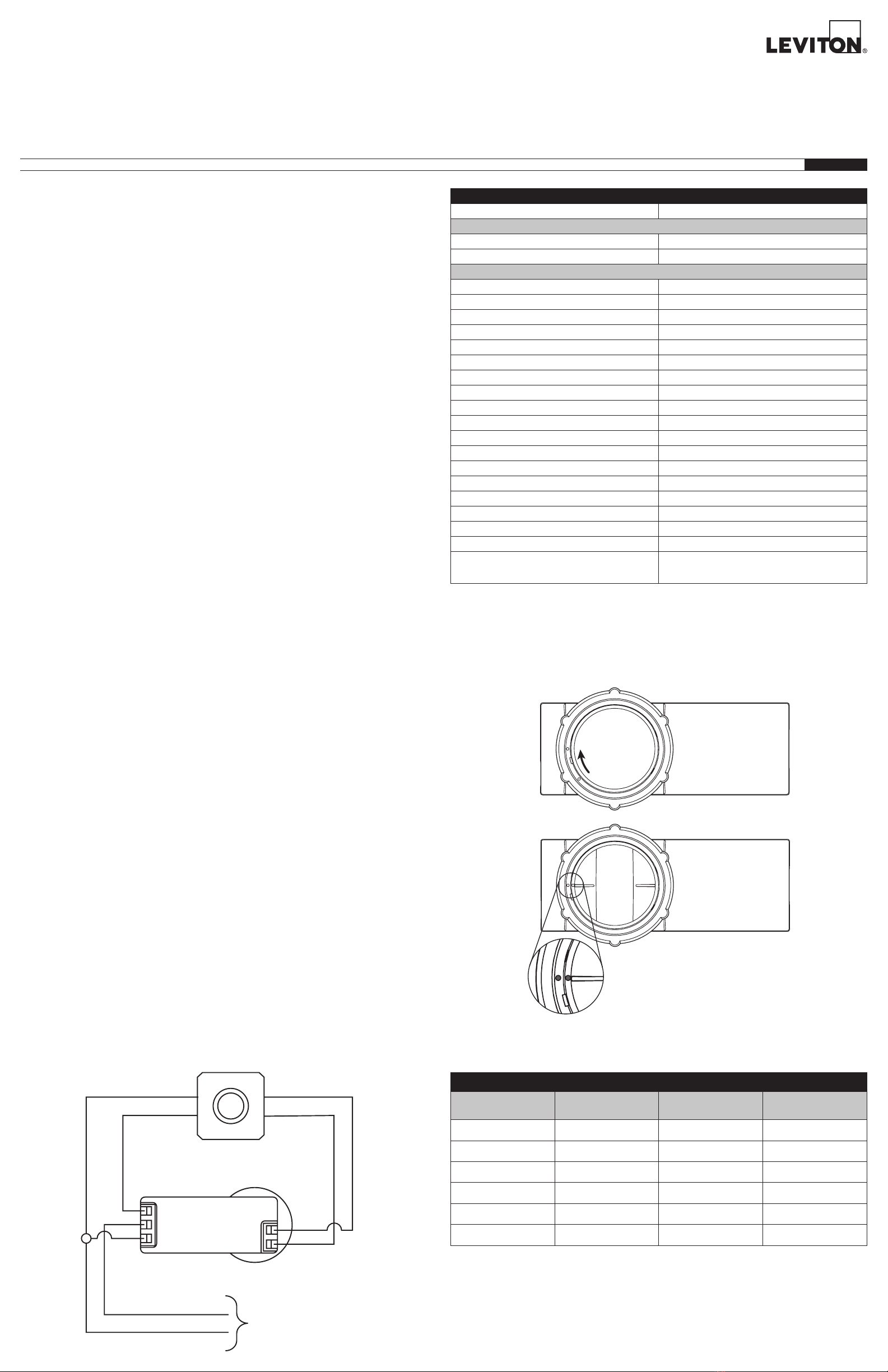
LENS ASSEMBLY DIMENSIONS
DIMENSION LOW BAY LENS HIGH BAY LENS
Lens Diameter 1.87 in.
(47.6 mm)
2.84 in.
(72 mm)
Lens Height 1.09 in.
(27.6 mm)
1.46 in.
(37 mm)
Operation
Photocell Operation
Daylight Mode: The Daylight mode and associated settings are configured using the Leviton
Smart Sensor App. These configuration options define how the sensor responds to ambient
lighting conditions.
• Ambient Light Hold OFF Mode (Daylighting): This mode is used for ON/OFF applications
to hold lights OFF when ambient light level exceeds a set threshold. When little or no
daylight is available, the sensor will turn ON the load. As daylight contribution increases and
crosses a configured threshold, the sensor will hold the load OFF. If light level drops below
the threshold for the duration of the Daylight Response Time (default 5 minutes), the hold
is released, and the load is turned ON. Ambient Light Hold OFF Threshold is derived by
the calibration routine when the photocell is in the Closed Loop mode. The daylight sensor
levels and response time can be adjusted using the Smart Sensor app.
• Daylight Harvesting Mode (Default): Daylight Harvesting adjusts the light levels in the
space through the full dimming range to maintain a Target Light Level based on the amount
of ambient light. When no daylight is available, the sensor allows the load to operate at its
maximum level. As daylight level increases in the space, the sensor dims the load. The
user can configure the lower dimming limit for Daylight Harvesting, including dim to OFF.
If dim to OFF is enabled, when the minimum dim level is reached and the measured light
level remains above target, the sensor will hold the lights off until the light level drops below
target for the duration of the Daylight Response Time (default 5 minutes). As the daylight
level decreases in the space, the sensor will increase the light output until the target is
reached. As the light levels change, the sensor will reduce or increase the light output to
maintain the target. The light level change occurs with a user configurable fade rate to
make the light level transition unnoticeable to occupants. The Target Light Level and other
Daylight Harvesting settings are configured in the Smart Sensor App.
• Ambient Light Match Mode (Reverse Daylight Harvesting): This mode adjusts the light
levels in the space through the full dimming range based on the amount of ambient light in
Open Loop mode and using a bi-level method in Closed Loop mode. When no daylight is
available, the sensor allows the load to operate at a defined partial level or lower limit. As
daylight level increases in the space, the sensor increases the light output. As the daylight
level decreases in the space, the sensor will decrease the light output until the lower limit
is reached. As the light levels change, the sensor will reduce or increase the light output
to minimize the visual transition for drivers or pedestrians entering or exiting an enclosed
artificially lit structure. The light level change occurs with a user configurable rate to make
the light level transition unnoticeable to occupants. The Target Light Level and other
Daylight Harvesting settings are configured in the Smart Sensor App.
NOTE: The Motion Indicator light will blink RED twice (2x) (once per second) for 2 seconds
each time motion is detected.
Occupancy Operation
Occupancy Mode: The Occupancy mode and associated settings are configured using the
Leviton Smart Sensor App. These configuration options define how the sensor responds
to occupancy.
• Occupancy (DEFAULT): In this mode, motion detection by the infrared sensor will turn the
lights ON as well as keep them ON.
• Photocell-Only (Occupancy Disabled): When in Photocell-Only mode, the Occupancy
Sensor is disabled, and the sensor ignores motion. In this mode the lights are ON and the
sensor performs daylighting/daylight harvesting only.
FCC STATEMENT:
This equipment has been tested and found to comply with the limits for a Class B digital device, pursuant to part 15 of
the FCC Rules. These limits are designed to provide reasonable protection against harmful interference in a residential
installation. This equipment generates, uses, and can radiate radio frequency energy and, if not installed and used
in accordance with the instructions, may cause harmful interference to radio communications. However, there is no
guarantee that interference will not occur in a particular installation. If this equipment does cause harmful interference to
radio or television reception, which can be determined by turning the equipment off and on, the user is encouraged to try
to correct the interference by one or more of the following measures:
- Reorient or relocate the receiving antenna.
- Increase the separation between the equipment and receiver.
- Connect the equipment into an outlet on a circuit different from that to which the receiver is connected.
- Consult the dealer or an experienced radio/TV technician for help.
IC Statement
This device contains license-exempt transmitter(s)/receiver(s) that comply with Innovation, Science and Economic
Development Canada’s license-exempt RSS(s). Operation is subject to the following two conditions: (1) This device may
not cause interference. (2) This device must accept any interference, including interference that may cause undesired
operation of the device.
Any changes or modifications not expressly approved by Leviton Manufacturing Co., could void the user’s authority to
operate the equipment.
LOAD
NEUTRAL
LINE
DIM (+)
DIM (-)
Test/Reset
Button
Status LED
Passive Infrared
(PIR) Sensor Photocell
(35 mm)
LENS
0.13 in.
(3.2 mm)
MAX WALL
THICKNES
LENS
(95 mm)
0.91 in.
Troubleshooting
• If sensor does not trigger when entering the room or space, increase the sensitivity level of
the sensor and/or check the daylighting settings (increase the daylighting level).
• To test the sensor's Field Of View (FOV), use Walk Test mode in the Smart Sensor App. The
Walk Test mode will temporarily reduce the timeout of the sensor to 15 seconds.
NOTE: Photocell Auto-Calibration will be paused while in Walk Test mode.
• To exit Walk Test mode:
- Disable it from the Smart Sensor App.
- Power Cycle the device.
- Walk Test mode will automatically time-out after 15 minutes. After exiting Walk Test
mode, normal Operation and/or Auto-Calibration will resume.
• If the lights constantly stay ON even when room is unoccupied:
- Check the Time-Out setting and confirm set to desired time.
- Try lowering the sensor sensitivity; if problem persists, try lowering again.
- Check for reflected heat/motion, as sensor may be seeing motion through a window.
- Check for adjacent HVAC and/or heater ducts.
• If you are unable to connect to the sensor from the App, resetting or restarting the device
may resolve connectivity issues.
- Soft Reset: To restart the sensor, press and hold the RESET/TEST button for
2 to 5 seconds. After 10 to15 seconds, the LED will blink BLUE five times (5x) to indicate
that the reset was successful.
- Hard Reset: To reset the sensor and return to factory defaults, press and hold the
RESET/TEST button for 20 to 25 seconds. If you exceed 25 seconds, no action
will be taken. The LED will blink BLUE at 20 seconds. After 10 to 15 seconds, the LED
will blink BLUE five times (5x) to indicate that the reset was successful.
• Where do I get help on App features?
- Contextual help is provided within the Leviton Smart Sensor App. For additional support,
please reach out to our Technical Service Team.
• If the LED on the sensor is flashing PURPLE, this indicates that the devices’ health check
failed. This is usually a hardware related problem. Disconnect power from the device for 30
seconds. If the problem persists after cycling power, please contact the Leviton Technical
Service Team at 1-800-824-3005.