manuals.online logo
Brands
  1. Home
  2. •
  3. Brands
  4. •
  5. Leviton
  6. •
  7. Home Automation
  8. •
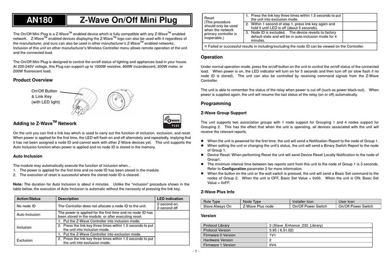
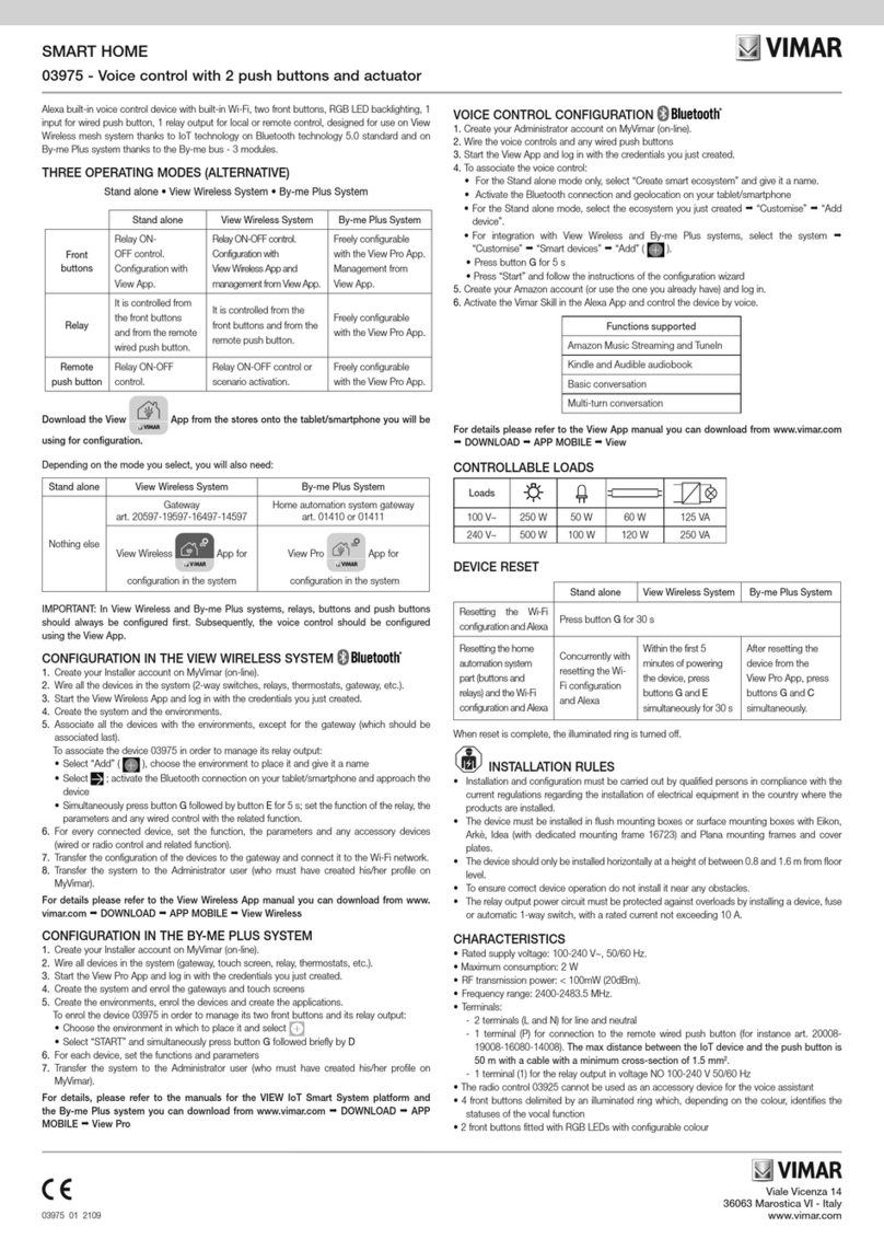
  9. Leviton UPB 5A00-1 User manual

Leviton UPB 5A00-1 User manual

YELLOW
BLUE
GRAY
CONTROL WIRE FROM
*NEUTRAL
*NEUTRAL
BLACK LINE
BOTTOM
(OFF/DIM)
(ON/BRIGHT)
TOP
(FOR RED INDICATOR)
(FOR BLUE INDICATOR)
INDICATO
R
LE
D
LEVITON UPB™
WALL SWITCH
INSTALLATION AND OPERATING INSTRUCTIONS ENGLISH
DI-02X-HL551-00A (55I00-1)
Figure 1 - 55A00-1 Leviton UPB™ Wall Switch Dimmer
WARNINGS AND CAUTIONS
•TO AVOID FIRE, SHOCK, OR DEATH; TURN OFF POWER at circuit breaker or fuse and test that power is off before wiring!
•To be installed and/or used in accordance with appropriate electrical codes and regulations.
•If you are unsure about any part of these instructions, consult an electrician.
•SAVE THESE INSTRUCTIONS.
WARNINGS AND CAUTIONS
•To reduce the risk of overheating and possible damage to other equipment, do not use switch, when set to dimming-capable, to
control a receptacle, a motor-operated appliance, a fluorescent lighting fixture or a transformer-supplied appliance.
•Use this device with copper or copper-clad wire only.
•For indoor use only.
About Your Leviton UPB™ Wall Switch Dimmer
The Leviton UPB™ Wall Switch Dimmer (Figure 1) is a high quality light-switch/dimmer that not only allows for local rocker
switch control of a lighting load but also incorporates UPB™ two-way powerline communication technology that gives it the
ability to be remotely controlled by other UPB™ compatible controllers. The Leviton UPB™ Wall Switch is highly configurable
to allow for behaviors customized to each individual’s desires. The Leviton UPB™ Wall Switch is capable of storing up to
16 preset light levels and fade rates to create powerful lighting scenes. The Leviton UPB™ Wall Switch is also capable of
transmitting UPB™ messages (including a current light level report) when rocker switch events occur. The Leviton UPB™
Wall Switch is capable of being set to a non-dimming mode in order to control such loads as fluorescent lights.
Using Your Leviton UPB™ Wall Switch Dimmer
The Leviton UPB™ Wall Switch Dimmer is packed full of different options and configurations that can be programmed into it
using the UPB™ UPStart configuration software. This section will describe the operation of the Leviton UPB™ Wall Switch
Dimmer in its factory default configuration. Please refer to the section entitled "Configuring the Leviton UPB™ Wall Switch
Dimmer" for a description of the many other configuration options available.
Using Your Leviton Auxiliary Switch
The Leviton UPB™ Wall Switch can (optionally) be connected to one or more Leviton Auxiliary Switch producing three,
four, or five-way lighting circuits. Each Leviton Auxiliary Switch has a Decora
®
rocker switch that can be used to control the
lighting load of the Leviton UPB™ Wall Switch in the same way as previously described in Table 2.
About Your 37A00-1 Leviton Auxiliary Switch
The 37A00-1 Leviton Auxiliary Switch (Figure 2) is a low cost (optional) companion device to the Leviton UPB™ Wall
Switch. The 37A00-1 has a rocker switch that controls the Leviton UPB™ Wall Switch in the same exact way that its local
rocker switch does.
Figure 2 – 37A00-1 Leviton Auxiliary Switch
Installation Instructions
The Leviton UPB™ Wall Switch Dimmer is wired directly to the lighting circuit and can (optionally) be controlled by one or
more Leviton Auxiliary Switch producing three, four, or five-way circuits. Multi-way circuits make it possible for a group of
switches to control the same set of lights. This section will illustrate how to hook-up the connections.
NOTES:
1. Refer to Figures 1 and 2 to determine the wire colors of the hook-up.
2. All Leviton UPB™ Wall Switch Dimmers require a neutral (white) connection.
3. Leviton Auxiliary Switches require that the Line (black) wire be accessible. This wire may be connected to either phase
of the 120/240V supply.
4. The blue and/or gray wire on the Leviton Auxiliary Switch Dimmer can be connected to either earth ground or neutral.
The blue and/or gray wire serves only to light the LED on the Auxiliary Switch. This LED does not indicate anything
except that power is applied and to serve as a night-light.
AIR-GAP SWITCH
The Leviton UPB™ Wall Switch rocker switch has an air-gap switch that will remove all power from the load for safe
installation and bulb replacement. To activate the air-gap switch firmly press the rocker bottom until you hear a loud "click"
or you see the SYSTEM "OFF" label on the top rocker.
Installation Procedure
1. Remove the faceplate from the existing wall switch.
2. Unscrew and pull the existing wall switch out of the wall box.
3. Disconnect the wires from the existing wall switch. Identify the "Line", "Neutral", "Load" and "Traveler" wires.
4. Install the 5 connecting wires per wiring configuration shown in Figure 3.
NOTE: Be sure that the Leviton UPB™ Wall Switch is in the SYSTEM "OFF" position by firmly pressing the Rocker
Bottom until you click the air-gap switch to the open position or you see the SYSTEM "OFF" label on top of the Rocker.
5. Optionally install any Leviton Auxiliary Switch per wiring configuration shown in Figure 3.
6. After all connections have been made, be certain that all wire connectors are firmly attached and there is no exposed
copper.
7. Gently place the wires and Wall Switch into the wall box, with light emitting diode (LED) at the top of device, and screw
in place.
8. Before installing the faceplate, restore power to the circuit, and firmly press the top of the Leviton UPB™ Wall Switch
Dimmer until it snaps out of the SYSTEM "OFF" position.
9. After testing the Leviton UPB™ Wall Switch Dimmer for proper local operation (per Table 2), install the faceplate
cover(s) to the outside of the Leviton UPB™ Wall Switch Dimmer(s).
BLACK
WHITE
RED
YELLOW
LINE
NEUTRAL
LOAD
CONTROL WIRE FROM
GROUND
TO
P
(ON/BRIGHT
)
BOTTO
M
(OFF/DIM
)
BREAK-OFF TABS
INDICATOR
LE
D
(wire must be capped off if not used)
AUXILIARY SWITCH
TO CASE
LEVITON UPB™ 1000W WALL SWITCH DIMMER AND AUXILIARY SWITCH
55A00-1 (Leviton UPB™ 1000W Wall Switch Dimmer)
37A00-1 (Leviton Auxiliary Switch)
Figure 3 – Wiring Diagram
LINE
NEUTRAL
37A00 (OPTIONAL)
AUXILIARY SWITCH
AUXILIARY SWITCH
37A00 (OPTIONAL) 55A00
Leviton Wall Switch
BLACKBLACK BLACK
REDWHITE
YELLOWYELLOW
*BLUE AND/OR GRAY*BLUE AND/OR GRAY
YELLOW
*CONNECTING THE BLUE AND/OR GRAY WIRE TO NEUTRAL SETS THE COLOR OF THE LED INDICATOR.
CONNECT BLUE FOR BLUE INDICATOR, GRAY FOR RED INDICATOR, OR BOTH FOR MAGENTA INDICATOR.
BLUE AND/OR GRAY WIRE MAY BE CONNECTED TO NEUTRAL OR EARTH GROUND. NEUTRAL IS RECOMMENDED.
COPPER
Local Rocker Switch Operation
The Leviton UPB™ Wall Switch Dimmer has a rocker switch that can be used to control the lighting load as described below
in Table 2.
Rocker Event Top Rocker Bottom Rocker
Single-Tap Brightens the light to 100% (on) at a
0.8-second fade rate.
Fades the light to 0% (off) at a 1.6-second
fade rate.
Double-Tap Snaps the light to 100% (on). Snaps the light to 0% (off).
Hold Starts fading (brightening) the light
towards 100% at a 3.3-second fade rate.
Starts fading (dimming) the light towards 0%
at a 3.3-second fade rate.
Release Stops brightening the light. Stops dimming the light.
Table 2: Rocker Switch Operation
LED Indicator
The Leviton UPB™ Wall Switch Dimmer comes equipped with a multi-color LED indicator that is normally lit to blue.
This LED indicator will blink different colors to indicate UPB™ communication status and configuration status as outlined
in Table 3 below.
Leviton UPB™ Wall Switch Dimmer Status LED Color
The load connected to the Leviton UPB™ Wall Switch Dimmer is off Blue
The load connected to the Leviton UPB™ Wall Switch Dimmer is on Black
Table 3: Status LED Operation
De-rating Information
For a proper fit in a multiple gang installation, it may be necessary to remove one or both sides (break-off tabs) from the
mounting plate (see Figure 1). When tabs are removed, the overall rating of the device must be reduced in accordance
with the following chart:
NOTE: When the 55A00-1 is mounted in a normal depth wall box it must also be de-rated from 1000W down to 900W.
Table 1: 55A00-1 De-rating Information
Model Device
Maximum
Load
No Fins
Removed Deep
Box
No Fins Removed
Normal Depth
Box
One Fin Removed
Next to One
Dimmer
Both Fins Removed
Next to Two
Dimmers
55A00-1 1000W 1000W 900W 800W 600W
WEB VERSION
For Technical Assistance Call: 800-824-3005 - www.leviton.com
DI-02X-HL551-00A (55I00-1)© 2013 Leviton Mfg. Co., Inc.
LEVITON LIMITED WARRANTY
Leviton warrants to the original consumer purchaser and not for the benefit of anyone else that products manufactured by Leviton under the Leviton brand name ("Product") will be free from defects in material and workmanship for the time periods indicated below, whichever is shorter: • OmniPro II and Lumina Pro: Three (3) years from installation or 42 months from manufacture date.
• OmniLT, Omni IIe, and Lumina: Two (2) years from installation or 30 months from manufacture date. • Thermostats, Accessories: Two (2) years from installation or 30 months from manufacture date. • Batteries: Rechargeable batteries in products are warranted for ninety (90) days from date of purchase. Note: Primary (non-rechargeable) batteries shipped in products are not warranted.
Products with Windows®Operating Systems: During the warranty period, Leviton will restore corrupted operating systems to factory default at no charge, provided that the product has been used as originally intended. Installation of non-Leviton software or modification of the operating system voids this warranty. Leviton’s obligation under this
Limited Warranty is limited to the repair or replacement, at Leviton’s option, of Product that fails due to defect in material or workmanship. Leviton reserves the right to replace product under this Limited Warranty with new or remanufactured product. Leviton will not be responsible for labor costs of removal or reinstallation of Product. The repaired or
replaced product is then warranted under the terms of this Limited Warranty for the remainder of the Limited Warranty time period or ninety (90) days, whichever is longer. This Limited Warranty does not cover PC-based software products. Leviton is not responsible for conditions or applications beyond Leviton’s control. Leviton is
not responsible for issues related to improper installation, including failure to follow written Installation and operation instructions, normal wear and tear, catastrophe, fault or negligence of the user or other problems external to the Product. To view complete warranty and instructions for returning product, please visit us at www.leviton.com.
FOR CANADA ONLY
For warranty information and/or product returns, residents of Canada should contact Leviton in writing at Leviton Manufacturing of Canada Ltd to the attention of the Quality Assurance Department, 165 Hymus Blvd, Pointe-Claire (Quebec), Canada H9R 1E9 or by telephone at 1 800 405-5320.
Configuring the Leviton UPB™ Wall Switch Dimmer
The Leviton UPB™ Wall Switch Dimmer is highly configurable. Many of its configuration options can only be enabled or
modified with the use of the UPB™ UPStart configuration software. Table 4 describes the many configuration options
available that can be set up with the use of the UPB™ UPStart configuration software.
NOTE: Although the factory default operation of the Leviton UPB™ Wall Switch is useful in many situations, it is highly
recommended that your Leviton UPB™ Wall Switch be configured with a Leviton controller or UPB™ UPStart configuration
software so that you can take advantage of its many configurable features.
Changing Preset Light Levels
The Leviton UPB™ Wall Switch Dimmer is specially designed to work with an Leviton controller consisting of Leviton Room
Controllers and Leviton House Controllers. Pushbuttons on these controllers can be configured to activate the Preset Light
Levels and Fade Rates stored in the Leviton UPB™ Wall Switch Dimmer. Once configured, the homeowner can easily adjust
the Preset Light Level that gets activated by a particular pushbutton by following this simple procedure.
Model Number 55A00-1
Incandescent Loads Dimming Yes
Inductive Loads Dimming Yes
Fluorescent Loads Non-dimming Yes (configurable)
Power Maximum Dimming 1000W / 1000VA
Current Maximum Non-dimming 8A
Connections 16 GA
LED Indicator Yes
Dimensions 4.3 X 2.5 X 1.9 in
Weight 0.3 lb.
Mounting Standard J box
Input Power 120 ± 12 VAC
Input Frequency 60 ± 3 Hz
Operating Temp -40 °F to 104 °F
SPECIFICATIONS
Setting Factory Defaults
The Leviton UPB™ Wall Switch Dimmer can be set back to its factory defaults by the following steps:
Step Operation
1 Identify the Leviton UPB™ Wall Switch Dimmer that you want to set factory defaults by tapping its rocker switch
5 times quickly.
2 The Leviton UPB™ Wall Switch Dimmer will flash its lighting load one time and blink its LED blue to indicate that
it is ready to be set to factory defaults.
3 Set the factory defaults by tapping its rocker switch 10 times quickly.
4 The Leviton UPB™ Wall Switch Dimmer will flash its lighting load one time and blink its LED red to indicate that
it has been set to factory defaults.
5 Tap the rocker twice to stop the blinking.
Putting the Wall Switch Dimmer Into Setup Mode
The Leviton UPB™ Wall Switch Dimmer can be put into the Setup Mode by the following steps:
Table 4: 55A00-1 UPB™ Wall Switch Configuration Options
Option Factory Default Possibilities
Dimming-Capable Yes Yes or No (on/off only)
Default Fade Rates On = 0.8 seconds
Off = 1.6 seconds
16 different fade rates from 0 (Snap) to 1 hour.
Top Rocker Single-Tap Action Fade to 100% at the
Default Fade Rate.
Any Level (0% - 100% including Last On Level) at any
of 16 Fade Rates.
Top Rocker Double-Tap Action Snap to 100%. Any Level (0% - 100% including Last On Level) at any
of 16 Fade Rates.
Bottom Rocker Single-Tap Action Fade to 0% at the
Default Fade Rate.
Any Level (0% - 100% including Last On Level) at any
of 16 Fade Rates.
Bottom Rocker Double-Tap Action Snap to 0%. Any Level (0% - 100% including Last On Level) at any
of 16 Fade Rates.
Rocker Switch UPB Transmissions Disabled Configure any of 15 different UPB Messages (including
Status Report) to be transmitted upon any Rocker
Switch Event.
UPB Transmission Attempts 2 1, 2, 3, or 4 transmissions per event.
Preset Light Levels and Fade Rates
(Scenes)
Linked to six
pushbuttons on the
Leviton 6-Button
Room Controller
Link as many as 16 different Preset Light Levels and
Fade Rates to components on UPB™ compatible
controllers.
UPB ID NID = 255
UID = 003
Many UPB Identification parameters can be configured
including the Network ID (NID), Unit ID (UID), Network
Password, Network Name, Room Name, Device Name,
etc.
LED Color Control (See Table 3) Any of 16 different LED modes consisting of the colors
blue, red, magenta, and black.
Step Operation
1 Press the pushbutton on the Leviton Room Controller or Leviton House Controller to activate the currently stored
Preset Light Level.
2 Use the local rocker switch on the Leviton UPB™ Wall Switch Dimmer to set the desired Preset Light Level.
3 Press the pushbutton on the Room Controller or House Controller five times quickly.
4 The Leviton UPB™ Wall Switch Dimmer will flash its lighting load one time to indicate that it stored the new
Preset Light Level.
Step Operation
1 Tap the Leviton UPB™ Wall Switch local (or remote) rocker switch 5 times quickly.
2 The Leviton UPB™ Wall Switch Dimmer will flash its lighting load one time and blink its LED blue to indicate that
it is in Setup Mode. NOTE: the device will automatically exit Setup Mode after 5 minutes.w
FCC COMPLIANCE
This equipment has been tested and found to comply with the limits for a Class B digital device, pursuant to part 15 of the FCC Rules. These limits are designed to provide reasonable protection against harmful interference in a residential installation. This equipment generates, uses and can radiate radio frequency energy and, if not installed and used in accordance with the
instructions, may cause harmful interference to radio communications. However, there is no guarantee that interference will not occur in a particular installation. If this equipment does cause harmful interference to radio or television reception, which can be determined by turning the equipment off and on, the user is encouraged to try to correct the interference by one or more
of the following measures:
•Reorient or relocate the receiving antenna.
•Increase the separation between the equipment and receiver.
•Connect the equipment into an outlet on a circuit different from that to which the receiver is connected.
•Consult the dealer or an experienced radio/TV technician for help.
COPYRIGHT AND TRADEMARK INFORMATION
This document and all its contents herein are subject to and protected by international copyright and other intellectual property rights and are the property of Leviton Manufacturing Co., Inc, its subsidiaries, affiliates and/or licensors. © 2013 Leviton Manufacturing Co., Inc. All rights reserved. Use herein of third party trademarks, service marks, trade names, brand names and/or
product names are for informational purposes only, are/may be the trademarks of their respective owners; such use is not meant to imply affiliation, sponsorship, or endorsement.
No part of this document may be reproduced, transmitted or transcribed without the express written permission of Leviton Manufacturing Co., Inc.
WEB VERSION

This manual suits for next models

1

Other Leviton Home Automation manuals

Leviton 35249 User manual

Leviton

Leviton 35249 User manual

Leviton Intellect ZL070-B00 User manual

Leviton

Leviton Intellect ZL070-B00 User manual

Leviton ZLD1Z-I0W User manual

Leviton

Leviton ZLD1Z-I0W User manual

Leviton TWR20-W User manual

Leviton

Leviton TWR20-W User manual

Leviton 5480 User manual

Leviton

Leviton 5480 User manual

Leviton smartlockpro GFNT1 User manual

Leviton

Leviton smartlockpro GFNT1 User manual

Leviton Decora Smart DG15S User manual

Leviton

Leviton Decora Smart DG15S User manual

Leviton Decora Smart DZPA1 User manual

Leviton

Leviton Decora Smart DZPA1 User manual

Leviton smartlockpro GFCI Manual

Leviton

Leviton smartlockpro GFCI Manual

Leviton ODCØP-S0W User manual

Leviton

Leviton ODCØP-S0W User manual

Leviton 47604-F6 User manual

Leviton

Leviton 47604-F6 User manual

Leviton Decora Smart DZ15R User manual

Leviton

Leviton Decora Smart DZ15R User manual

Leviton IUM1H User manual

Leviton

Leviton IUM1H User manual

Leviton WSG15-0DZ User manual

Leviton

Leviton WSG15-0DZ User manual

Leviton 5250 User manual

Leviton

Leviton 5250 User manual

Leviton 35249 User manual

Leviton

Leviton 35249 User manual

Leviton T5261-CH User manual

Leviton

Leviton T5261-CH User manual

Popular Home Automation manuals by other brands

Velleman VMB1DM manual

Velleman

Velleman VMB1DM manual

Zipato ZIPABOX user guide

Zipato

Zipato ZIPABOX user guide

Hama 00176531 operating instructions

Hama

Hama 00176531 operating instructions

Cnct intelliPLUG quick start guide

Cnct

Cnct intelliPLUG quick start guide

Nordic DELTACO SH-P01 user manual

Nordic

Nordic DELTACO SH-P01 user manual

COHERE maxem installation manual

COHERE

COHERE maxem installation manual

MO Molekule Air Mini user manual

MO

MO Molekule Air Mini user manual

TWC Zipscreen Programming instructions

TWC

TWC Zipscreen Programming instructions

RADEMACHER RolloHomeControl Troll Standard 3650 03 12 Operating and assembly manual

RADEMACHER

RADEMACHER RolloHomeControl Troll Standard 3650 03 12 Operating and assembly manual

HomeMatic HmIP-SWDM quick start guide

HomeMatic

HomeMatic HmIP-SWDM quick start guide

IOT RF Series user manual

IOT

IOT RF Series user manual

nekos KATO SYNCRO instruction manual

nekos

nekos KATO SYNCRO instruction manual

basIP AV-07T manual

basIP

basIP AV-07T manual

AirLive Smart Life SP-101-JP Quick installation guide

AirLive

AirLive Smart Life SP-101-JP Quick installation guide

WOOX R6113 quick start guide

WOOX

WOOX R6113 quick start guide

xtorm XA2065 manual

xtorm

xtorm XA2065 manual

SCS Sentinel Sone manual

SCS Sentinel

SCS Sentinel Sone manual

TP-Link Kasa Smart HS103P4 user guide

TP-Link

TP-Link Kasa Smart HS103P4 user guide

manuals.online logo
manuals.online logoBrands
  • About & Mission
  • Contact us
  • Privacy Policy
  • Terms and Conditions

Copyright 2025 Manuals.Online. All Rights Reserved.