LG LWHD1200R User manual

LG
Room
Air Conditioner
SERVICE MANUAL
LG
MODEL: LWHD1200R
CAUTION
website http://www.lgservice.com
• BEFORE SERVICING THE UNIT, READ THE SAFETY
PRECAUTIONS IN THIS MANUAL.
• ONLY FOR AUTHORIZED SERVICE PERSONNEL.

2Room Air Conditioner
Air Conditioner Service Manual
TABLE OF CONTENTS
Safety Precautions..........................................................................................................................................3
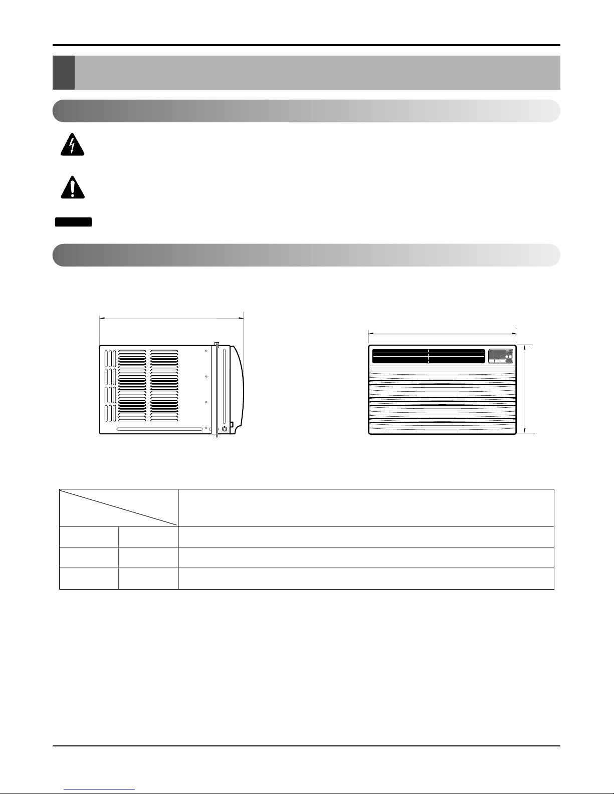
Dimensions .....................................................................................................................................................5
Outside Dimensions...................................................................................................................................5
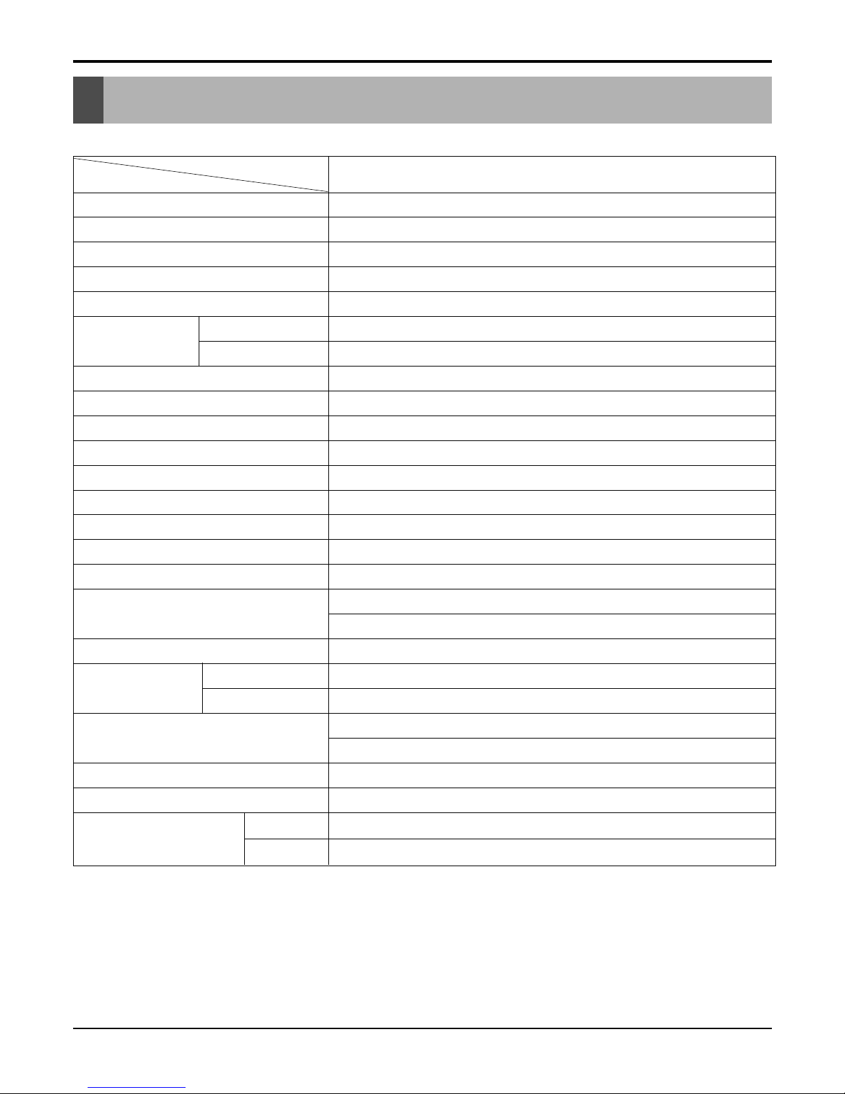
Product Specifications ..................................................................................................................................6
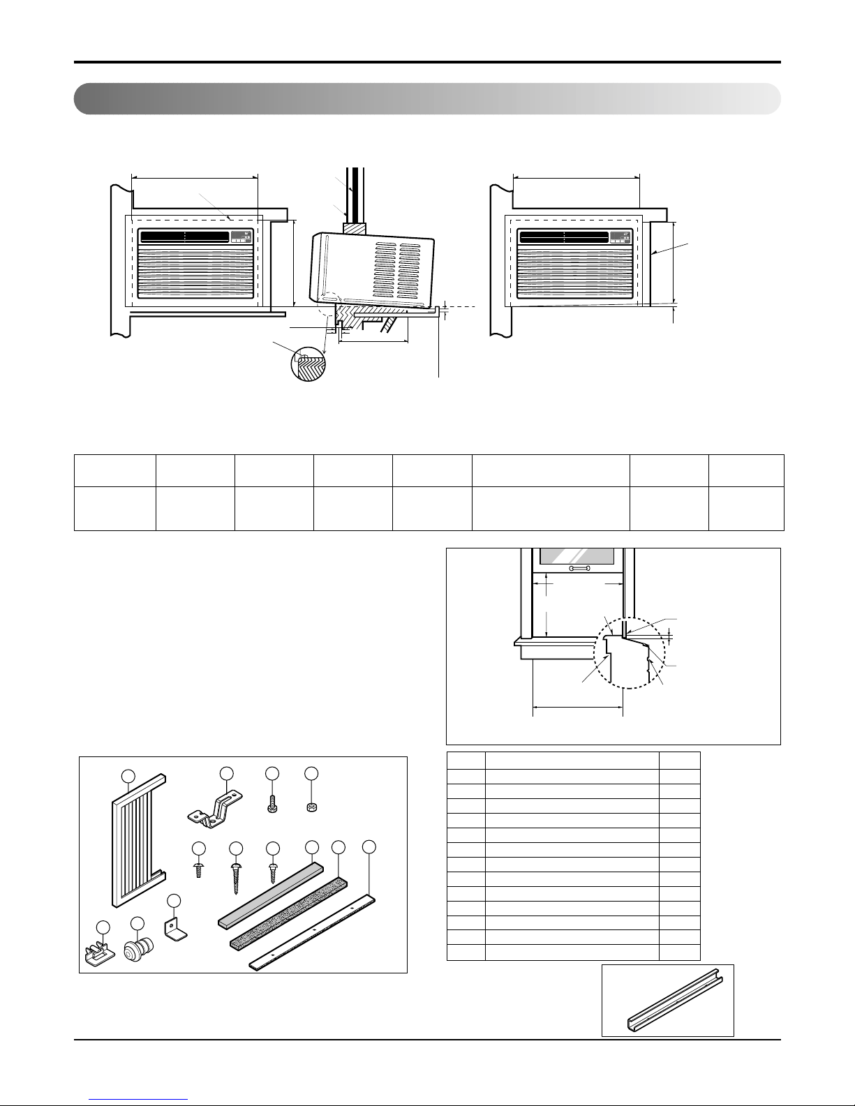
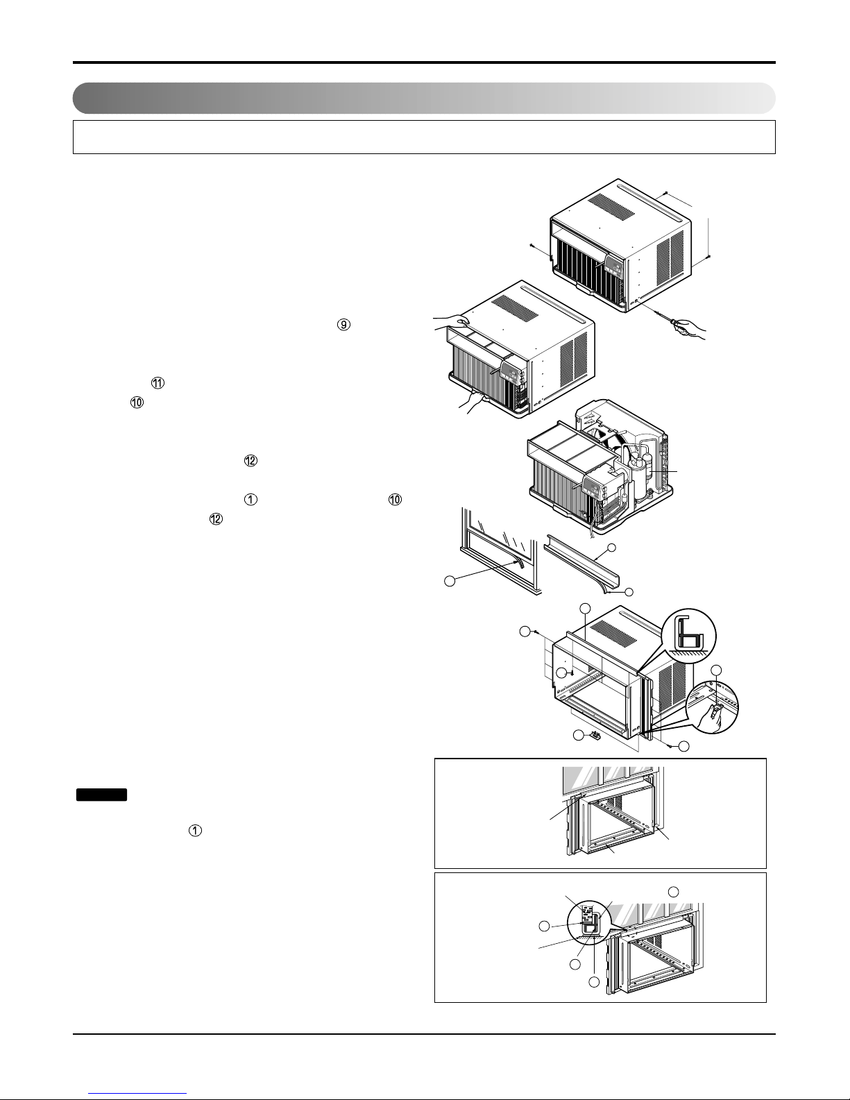
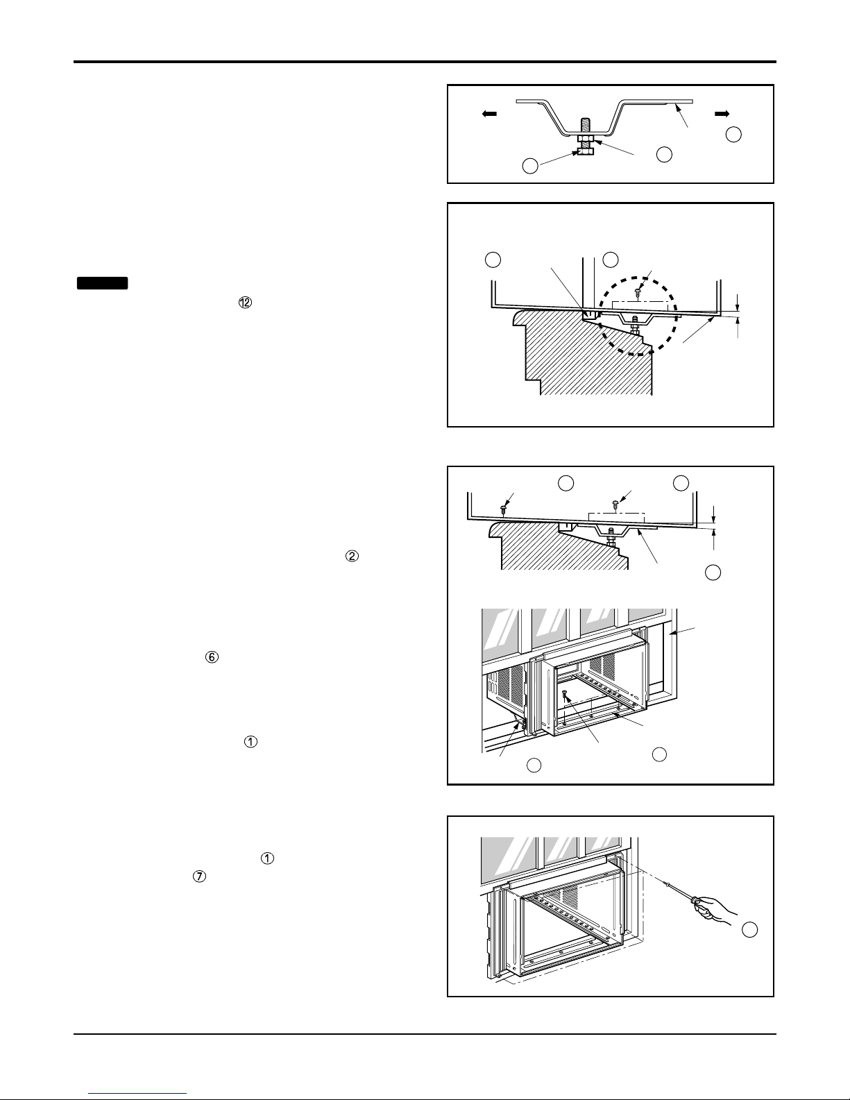
Installation.......................................................................................................................................................7
Select the Best Location ............................................................................................................................7
Installation Check.......................................................................................................................................7
How to Secure the Drain Pipe....................................................................................................................7
How to Install..............................................................................................................................................8
Suggested Tool Requirements...................................................................................................................9
Operation ......................................................................................................................................................12
Function of Controls.................................................................................................................................12
Disassembly ..................................................................................................................................................13
Mechanical Parts......................................................................................................................................13
Air handling Parts.....................................................................................................................................14
Electrical Parts .........................................................................................................................................15
Refrigerating Cycle...................................................................................................................................17
Schematic Diagram.......................................................................................................................................20
Electronic Control Device.........................................................................................................................20
Wiring Diagram.........................................................................................................................................21
Components Location ..............................................................................................................................22
Troubleshooting Guide.................................................................................................................................23
Pipeing System ........................................................................................................................................23
Troubleshooting Guide .............................................................................................................................23
Electrical Parts Troubleshooting Guide ....................................................................................................26
Electrical Parts .........................................................................................................................................30
Exploded View ..............................................................................................................................................36
Replacement Parts List ................................................................................................................................37

Service Manual 3
Safety Precautions
Safety Precautions
To prevent injury to the user or other people and property damage, the following instructions must
be followed.
■Incorrect operation due to ignoring instruction will cause harm or damage. The seriousness is
classified by the following indications.
■Meanings of symbols used in this manual are as shown below.
WARNING
CAUTION
This symbol indicates the possibility of death or serious injury.
This symbol indicates the possibility of injury or damage to property only.
Be sure not to do.
Be sure to follow the instruction.
WARNING
■Installation
Do not use damaged power cord plugs, or a
loose socket.
• There is risk of fire or electric shock.
Always use the power plug and socket with
the ground terminal.
• There is risk of electric shock.

4Room Air Conditioner
Safety Precautions
Do not modify or extend the power cord.
• There is risk or fire or electric shock.
Do not install, remove, or re-install the unit by
yourself(customer).
• There is risk of fire, electric shock, explosion, or injury.
Be cautious when unpacking and installing
the product.
• Sharp edges could cause injury. Be especially careful
of the case edges and the fins on the condenser and
evaporator.
Do not store or use flammable gas or com-
bustibles near the air conditioner.
• There is risk of fire or failure of product.
Be sure the installation area does not deterio-
rate with age.
• If the base collapses, the air conditioner could fall with
it, causing property damage, product failure, and per-
sonal injury.
Sharp
edges
Gasolin

Service Manual 5
Dimensions
Dimensions
D
W
H
˚C
TIMER POWERMODE
TEMP
FAN
SPEED
F1LOW
F2MED
F3HIGH
Dry Timer
Fan
Energy
Saver
Cool
W mm(inch) 600(23 5/8)
H mm(inch) 380(14 31/32)
D mm(inch) 567(22 5/16)
Model
Dimension
HBLG1203R / R1200E
Outside Dimensions
This symbol alerts you to the risk of electric shock.
This symbol alerts you to hazards that could cause harm to the
air conditioner.
This symbol indicates special notes.
NOTICE
Symbols Used in this Manual

6Room Air Conditioner
Specfications
Product Specifications
POWER SUPPLY
COOLING CAPACITY (Btu/h)
INPUT (W)
RUNNING CURRENT (A)
E.E.R (BTU/W.h)
INDOOR (°C)
OUTDOOR (°C)
REFRIGERANT (R-22) CHARGE
EVAPORATOR
CONDENSER
FAN, INDOOR
FAN, OUTDOOR
FAN SPEEDS, FAN/COOLING
FAN MOTOR
OPERATION CONTROL
ROOM TEMP. CONTROL
AIR DIRECTION CONTROL
CONSTRUCTION
PROTECTOR COMPRESSOR
FAN MOTOR
POWER CORD
DRAIN SYSTEM
NET WEIGHT (lbs/kg)
OUTSIDE DIMENSION (inch)
(W x H x D) (mm)
1ø, 115, 60Hz
12,000
1,220
11.0
9.8
19.4(WB)**
23.9(WB)**
490(17.3 oz)
2 ROW 12 STACKS
2 ROW17 STACKS
TURBO FAN
PROPELLER TYPE FAN WITH SLINGER RING
3/3
6 POLES
REMOTE CONTROLLER
THERMISTOR
VERTICAL LOUVER (RIGHT & LEFT)
HORIZONTAL LOUVER (UP & DOWN)
SLIDE IN-OUT CHASSIS
OVERLOAD PROTECTOR
INTERNAL THERMAL PROTECTOR
(3 WIRE WITH GROUDING)
ATTACHMENT PLUG (CORD-CONNECTED TYPE)
DRAIN PIPE OR SPLASHED BY FAN SLINGER
79/36
235/8x 1431/32 x 225/16
600 x 380 x 567
LWHD1200R
MODELS
ITEMS
OPERATING
CONDITION
* DB:Dry Bulb
**
WB:Wet Bulb

Service Manual 7
Installation
Installation
Select the Best Location
Installation Check
How to Secure the Drain Pipe
1.To prevent vibration and noise, make sure the unit is
installed securely and firmly.
2.Install the unit where the sunlight does not shine direct-
ly on the unit.
3.The outside of the cabinet must extend outward for at
least 12" and there should be no obstacles, such as a
fence or wall, within 20" from the back of the cabinet
because it will prevent heat radiation of the condenser.
Restriction of outside air will greatly reduce the cooling
efficiency of the air conditioner.
CAUTION: All side louvers of the cabinet
must remain exposed to the outside of
the structure.
4.Install the unit a little slanted so the back is slightly lower
than the front (about 1/2"). This will help force con-densed
water to the outside.
5.Install the unit from the bottom about 30"~60" above the
floor level.
The setting conditions must be checked prior to initial starting.
The following items are especially important checking points when the installation is finished.
1. Grounding wire (Green or Green and Yellow) is provided in the power cord. The green wire must be grounded.
2. Connect to a single-outlet 15A circuit.
(or 20A circuit for Electric Heater Model)
3. To avoid vibration or noise, make sure the air conditioner is installed securely.
4 Avoid placing furniture or draperies in front of the air inlet and outlet.
In humid weather, excess water may cause the BASE PAN to overflow. To drain
the water, remove the DRAIN CAP and secure the DRAIN PIPE to the rear hole
of the BASE PAN. Press the drain pipe into the hole by pushing down and away
from the fins to avoid injury.
Optional
1. Install the drain pan over the corner of the cabinet where you removed
the plug with 4 (or 2) screws.
2. Connect the drain hose to the outlet located at the bottom of the drain
pan. You can purchase the drain hose or tubing locally to satisfy your
particular needs. (Drain hose is not supplied).
3. Select the most appropriate connection from among the following figures
(by considering the hole of the unit) to fit drain pan to your own unit.
AWNING
COOLED AIR HEAT
RADIATION
30"~60"
ABOUT 1/2"
Over 20"
FENCE
Drain pipe
Drain cap
Fig. 4
Fig. 3
Fig. 2
DRAIN
PAN DRAIN HOSE
Fig. 1
CABINET SCREW
Figure 1

8Room Air Conditioner
Installation
How to Install
When Using Gasket
When Using Installation Kits
1. Window Requirements
This unit is designed for installation in
standard double hung windows with actual opening
widths from 27" to 39".
The top and bottom window sash must open suffi-
ciently to allow a clear vertical opening of 16" from
the bottom of the upper sash to the window stool.
2. Installation Kits Contents
A
B
2A
RIGHT SIDE
HORIZONTAL
LINE
B
DE
F
H
3
4
2
1
˚C
TIMER POWERMODE
TEMP
FAN
SPEED
F1LOW
F2MED
F3HIGH
Dry Timer
Fan
Energy
Saver
Cool
˚C
TIMER POWERMODE
TEMP
FAN
SPEED
F1LOW
F2MED
F3HIGH
Dry Timer
Fan
Energy
Saver
Cool
1. WINDOW (WIDTH-A, HEIGHT-B)
2. GASKET
3. WALL
4. DETAILS 5.1 x 30 ROUND HEAD WOOD
SCREWS
ABCDE F HI
625mm 392mm 280mm 30mm 0~25mm OVER 420mm 5~10mm -5~5mm
(245/8") (157/16") (111/32") (11/16") (0~1") (OVER 1617/32") (3/16"~3/8") (-3/16"~3/16")
27" to 39"
16" min Stool
Interior wall
235/8" min
(Without frame curtain)
Offset
1/2" to 11/4"
Sill
Exterior
12 3 4
811
12
9
765
10
13
■Top retainer bar is in
the product package.
NO. NAME OF PARTS Q'TY
1 FRAME CURTAIN 2
2 SILL SUPPORT 2
3 BOLT 2
4 NUT 2
5
SCREW(TYPE A) (10mm(2/5"))
16
6
SCREW(TYPE B)
3
7
SCREW(TYPE C)
5
8 FOAM-STRIP 1
9
FOAM-PE (600mm x 25mm x 2mm)
1
10
WINDOW LOCKING BRACKET
1
11
FOAM-PE
(920mm x 30mm x 2mm)
1
12 DRAIN PIPE 1
13 FRAME GUIDE 2
D5.1mm(0.2")/16mm(0.63")
D4.1mm(0.17")/16mm(0.63")

Service Manual 9
Installation
Suggested Tool Requirements
SCREWDRIVER (+, -), RULER, KNIFE, HAMMER, PENCIL, LEVEL
Preparation of Chassis
1. Remove the screws that fasten the cabinet at both
sides and at the back.
2. Slide the unit out from the cabinet by gripping the
base pan handle and pulling forward while
bracing the cabinet.
3. Cut the window sash seal to the proper length. Peel
off the backing and attach the Foam-Pe to the
underside of the window sash.
4. Remove the backing from the top upper guide
Foam PE and attach it to the bottom of the Upper
Guide .
5. Attach the upper guide onto the top of the cabinet
with 3 type A screws.
6. Insert the Frame Guides into the bottom of the
cabinet.
7. Insert the Frame Curtain into the upper guide
and Frame Guides .
8. Fasten the curtains to the unit with 4 Type A screws
at the both sides.
Cabinet Installation
1. Open the window. Mark a line on center of the win-
dow stool (or desired air conditioner location).
Carefully place the cabinet on the window stool and
align the center mark on the front angle with the
center line marked in the window stool.
2. Pull the bottom window sash down behind the
upper guide until it meets.
Do not pull the window sash down so
tightly that the movement of Frame
Curtain is restricted.
NOTICE
Shipping
Screws
9
10
13
(Type A)
(Type A)
5
5
11
11
9
5
EPS Material
Upper Guide Window stool
Front Angle
Window Sash Upper guide
9
Frame Curtain
1
Foam-pe
10
Foam-pe
13
Cabinet
˚C
TEMP
F1LOW
F2MED
F3HIGH
Dry Timer
Fan
Energy
Saver
Cool
TIMER POWERMODE
FAN
SPEED
˚C
TEMP
F1LOW
F2MED
F3HIGH
Dry Timer
Fan
Energy
Saver
Cool
TIMER POWERMODE
FAN
SPEED
˚C
TEMP
F1LOW
F2MED
F3HIGH
Dry Timer
Fan
Energy
Saver
Cool
TIMER POWERMODE
FAN
SPEED
Figure 2
Figure 3

10 Room Air Conditioner
Installation
INDOOR OUTDOOR
Sill Support
Nut
Bolt
2
4
3
INDOOR OUTDOOR
12
7
5
Frame Guide
About 1/2"
Screw(Type A)
Cabinet
6
2
About 1/2"
Screw(Type B) 5
Screw(Type A)
Sill support
Type C
Sash track
Front Angle
Screw(Type B) 6
Sill support 2
3. Loosely assemble the sill support using the parts
in Figure 4.
4. Select the position that will place the sill
support near the outer most point on sill
(See Figure 4)
Be careful when you install the cabinet
(Frame Guides are broken easily).
5. Attach the sill support to the cabinet track hole in
relation to the selected position using
2 Type A screws in each support (See Figure 5).
6. The cabinet should be installed with a very slight
tilt (about 1/2") downward toward the outside
(See Figure 6).
Adjust the bolt and the nut of Sill Support for
balancing the cabinet.
7. Attach the cabinet to the window stool by
driving the screws (Type B) through the front
angle into window stool (5/8").
8. Pull each Frame Curtain properly to each win-
dow sash track, and repeat step 2.
9. Attach each Frame Curtain to the window sash
by using screws (Type C).
(See Figure 7)
NOTICE
Figure 4
Figure 5
Figure 6
Figure 7

Service Manual 11
Installation
Screw(Type A) Screw(Type A)
Power cord
13
8
Foam-Strip
˚C
TEMP
F1LOW
F2MED
F3HIGH
DryTimer
Fan
Energy
Saver
Cool
TIMERPOWER
MODE
FAN
SPEED
˚C
TEMP
F1LOW
F2MED
F3HIGH
Dry Timer
Fan
Energy
Saver
Cool
TIMER POWER
MODE
FAN
SPEED
˚C
TIMER POWERMODE
TEMP
FAN
SPEED
F1LOW
F2MED
F3HIGH
Dry Timer
Fan
Energy
Saver
Cool
10. Slide the unit into the cabinet.(See Fig. 8)
CAUTION:
For security purpose, reinstall
screws (Type A) at the cabinet's sides.
11. Cut the Foam-Strip to the proper length and insert
between the upper and lower window sash.
(See Fig. 9)
12. Attach the window Locking Bracket with a type C
screw. (See Fig. 10)
13. Attach the front grille to the cabinet by inserting the
tabs on the grille into the tabs on the front of the cab-
inet. Push the grille in until it snaps into place.(See
Fig. 11)
14. Lift the inlet grille and secure it with a type A screw
through the front grille.(See Fig. 12)
Figure 11
Figure 8
Figure 9
Figure 10
Figure 13
Figure 12

12 Room Air Conditioner
Operation
•Designed for COOLING ONLY.
•Powerful and whispering cooling.
•Slide-in and slide-out chassis for the simple instal-
lation and service.
•Low air-intake, top cooled-air discharge.
•Built-in adjustable Thermistor
•Washable one-touch filter
•Compact size
•Reliable and efficient rotary compressor
REMOTE CONTROL
DISPLAY
Power
Temp
Fan Speed
Timer Mode
1
2
3
4
5
˚C
TIMER POWERMODE
TEMP
FAN
SPEED
F1 LOW
F2 MED
F3 HIGH
Dry Timer
Fan
Energy
Saver
Cool
1
2
6
3 45
PRECAUTION:
The Remote Control unit will not
function properly if bright light strikes the sensor
window of the air conditioner or if there are obstacles
between the Remote Control unit and the air conditioner.
POWER BUTTON
To turn the air conditioner ON, push the button. To turn the air conditioner OFF, push the button again.
This button takes priority over any other buttons.
ROOM TEMPERATURE SETTING BUTTON
This button can automatically control the temperature of the room. The temperature can be set within a range of 60°F to
86°F by 1°F. (16°C to 30°C by 1°C)
Select the lower number for lower temperature of the room.
OPERATION MODE SELECTION BUTTON
Every time you push this button, it will shift among COOL, ENERGY SAVER, FAN and DRY.
-
Energy Saver: If Energy Save mode is selected, the fan stops when the compressor stops cooling.a
Approximately every 3 minutes the fan will turn on and check the room air to determine if cooling is needed.
FAN SPEED SELECTOR
Every time you push this button, it is set as follows.
(Hi [F3] ➔ Low [F1] ➔ Med [F2] ➔ Hi [F3] ➔ Low [F1] ➔...)
ON/OFF TIMER BUTTON
You can set the time when the unit will turn on or turn off automatically by pressing the timer button. If the unit is operating,
this button controls the time it will be turned off. If the unit is off state, this button controls the time it will start. Every time
you push this button, the remaining time will be set as follows.
- Stopping operation
(1Hour ➔ 2Hours ➔3Hours ➔4Hours ➔ 5Hours ➔6Hours ➔7Hours ➔8Hours ➔9Hours ➔10Hours ➔11Hours ➔
12Hours ➔0Hour ➔ 1Hour ➔ 2Hours ➔... )
- Starting operation
(1Hour ➔ 2Hours ➔3Hours ➔4Hours ➔ 5Hours ➔6Hours ➔7Hours ➔8Hours ➔9Hours ➔10Hours ➔11Hours ➔
12Hours ➔off ➔ 1Hour ➔ 2Hours ➔ ... )
REMOCON SIGNAL RECEIVER
6
6
Operation
Function of Controls

Service Manual 13
Disassembly
Disassembly
Mechanical Parts
—Before the following disassembly, set the CONTROL BOX to OFF and disconnect the power cord.
1. Front Grille
1. Open the lnlet grille downward and remove the air filter.
2. Remove the screw that fastens the front grille.(See
Figure 14)
3. Pull the front grille from the right side.
4. Remove the front grille.(There are 4 hooks.)
5. Re-install the components by referring to the removal
procedure, above.
2. Cabinet
1. After disassembling the FRONT GRILLE, remove the 2
screws that fasten the cabinet at both sides.
2. Remove the 2 screws that fasten the cabinet at back.
3. Pull the base pan forward. (See Figure 15)
4. Remove the cabinet.
5. Re-install the components by referring to the removal
procedure, above.
3. Control Box
1. Remove the front grille. (Refer to section 1)
2. Remove the cabinet. (Refer to section 2)
3. Remove the 2 screws that fasten the power cord.
4. Disconnect the grounding screw from the evaporator
channel.
5. Remove the 1 screw that fasten the control box cover.
6. Remove the housing which connects PCB and motor
wire in the control box.
7. Disconnect the housing that connects Plazma Air
Purifier.(Optional)
8. Remove the screw at left cover of filter case and open
the cover to remove inner screw. (Optional)
9. Remove the nut that fastens the terminal cover.
10. Remove the terminal cover.
11. Remove all the leads from the overload protector.
12. Discharge the capacitor by placing a 20,000 ohmre-
sistor across the capacitor terminals.
13. Raise the control box upward completely.
(See Figure 16)
14. Re-install the components by referring to the removal
procedure, above.
(Refer to the circuit diagram found on page 32 in this
manual and on the control box.)
˚C
TEMP
F1LOW
F2MED
F3HIGH
Dry Timer
Fan
Energy
Saver
Cool
TIMERPOWER
MODE
FAN
SPEED
˚C
TEMP
F1LOW
F2MED
F3HIGH
DryTimer
Fan
Energy
Saver
Cool
TIMER POWER
MODE
FAN
SPEED
˚C
TEMP
F1LOW
F2MED
F3HIGH
DryTimer
Fan
Energy
Saver
Cool
TIMER POWER
MODE
FAN
SPEED
Figure 14
Figure 16
Figure 15

14 Room Air Conditioner
Disassembly
Figure 17
Figure 18
Figure 19
Figure 20
4. Air Guide and Turbo Fan
1. Remove the front grille. (Refer to section 1)
2. Remove the cabinet. (Refer to section 2)
3. Remove the control box. (Refer to section 3)
4. Remove the 4 screws that fasten the brace.
5. Remove the brace.
6. Remove the 2 screws that fasten the air guide
upper.
7. Remove the air guide upper.(See Figure 17)
8. Remove the 2 screws that fasten the evaporator.
9. Move the evaporator forward and pulling it upward
slightly. (See Figure 18)
10. Pull out the hook of orifice by pushing the tabs
and remove it. (See Figure 19)
11. Remove the clamp with hand pliers which
secures the turbo fan.
12. Remove the turbo fan.
13. Remove the 2 screws that fasten the air guide
from the base pan.
14. Move the air guide backward, and pull out from
the base pan.(Move the air giude lower carefully.)
15. Re-install the components by referring to the
removal procedure, above.
5. FAN
1. Remove the cabinet. (Refer to section 2)
2. Remove the brace (Refer to section 4)
3. Remove the 5 screws which fasten the condenser.
4. Move the condenser to the left carefully.
5. Remove the clamp that secures the fan.
6. Remove the fan. (See Figure 20)
7. Re-install by referring to the removal procedure.
Air Handling Parts

6. Shroud
1. Remove the fan. (Refer to section 2.2.2)
2. Remove the shroud. (See Figure 8)
3. Re-install the components by referring to the
removal procedure, above.
7. Overload Protector
1. Remove the cabinet. (Refer to section 2)
2. Remove the nut that fastens the terminal cover.
3. Remove the terminal cover. (See Figure 22)
4. Remove all the leads from the overload protec-
tor.
5. Remove the overload protector.
6. Re-install the components by referring to the
removal procedure, above.
8. Compressor
1. Remove the cabinet. (Refer to section 2)
2. Discharge the refrigerant system using a
FreonTM Recovery System.
If there is no valve to attach the recovery sys-
tem, install one (such as a WATCO A-1) before
venting the FreonTM. Leave the valve in place
after
servicing the system.
3. Remove the overload protector. (Refer to sec-
tion 7)
4. After purging the unit completely, unbraze the
suction and discharge tubes at the compressor
connections.
5. Remove the 3 nuts and the 3 washers which
fasten the compressor.
6. Remove the compressor. (See Figure 23)
7. Re-install the components by referring to the
removal procedure, above.
Service Manual 15
Disassembly
Electrical Parts
Figure 21
Figure 22
Figure 23

16 Room Air Conditioner
Disassembly
9. Capacitor
1. Remove the control box. (Refer to section 3)
2. Open the top cover from the control box.
(See Figure 24)
3. Pull out the capacitor from the control box.
4. Disconnect all the leads of capacitor terminals.
5. Re-install the components by referring to the
removal procedure, above.
10. Power Cord
1. Remove the control box. (Refer to section 3)
2. Open the top cover from the control box.
(Refer to section 9)
3. Disconnect the front panel from the control box.
(See Figure 25)
4. Disconnect two leads from the capacitor and
relay.
5. Pull out the power cord.
6. Re-install the component by referring to the
above removal procedure, above.
(Use only one ground-marked hole for ground
connection.)
7. If the supply cord of this appliance is damaged, it
must be replaced by the special cord.
(The special cord means the cord which has the
same specification marked on the supply cord
attached at the unit.)
˚C
TEMP
F1 LOW
F2 MED
F3 HIGH
Dry Timer
Fan
Energy
Saver
Cool
TIMER POWER
MODE
FAN
SPEED
˚C
TEMP
F1LOW
F2MED
F3HIGH
DryTimer
Fan
Energy
Saver
Cool
TIMER POWER
MODE
FAN
SPEED
Figure 25
Figure 24

Service Manual 17
Disassembly
11. Motor
1. Remove the cabinet. (Refer to section 2)
2. Remove the turbo fan. (Refer to section 4)
3. Remove the fan. (Refer to section 5)
4. Remove the 4 screws that fasten the motor from
the air guide. (See Figure 26)
5. Remove the motor.
6. Re-install the components by referring to the
removal procedure, above.(See Figure 26)
12. Condenser
CAUTION: Discharge the refrigerant
system using a FreonTM Recovery
System. If there is no valve to attach the
recovery system, install one (such as a
WATCO A-1) before venting the FreonTM.
Leave the valve in place after servicing
the system.
1. Remove the cabinet. (Refer to section 2)
2. Remove the 4 screws that fasten the
brace.(Refer to section 4)
3. Remove the 5 screws that fasten the condenser
and shroud.
4. After discharging the refrigerant completely,
unbraze the interconnecting tube at the con-
denser connections.
5. Remove the condenser.
6. Re-install the components by referring to notes.
(See Figure 27)
13. Evaporator
1. Remove the control box.(Refer to section 3)
2. Remove the air guide upper. (Refer to section 4)
3. Remove the 2 screws that fasten the evapora-
tor.
4. Move the evaporator sideways carefully.
(Refer to section 4)
5. After discharging the refrigerant completely,
unbraze the interconnecting tube at the evapo-
rator connections.
6. Remove the evaporator.
7. Re-install the components by referring to notes.
(See Figure 28)
Figure 26
Figure 27
Figure 28
Refrigerating Cycle

18 Room Air Conditioner
Disassembly
—Replacement of the refrigeration cycle.
1. When replacing the refrigeration cycle, be sure to
Discharge the refrigerant system using a FreonTM
recovery System.
If there is no valve to attach the recovery system,
install one (such as a WATCO A-1) before venting
the FreonTM. Leave the valve in place after
servicing the system.
2. After discharging the unit completely, remove the
desired component, and unbraze the pinch-off
tubes.
3. Solder service valves into the pinch-off tube ports,
leaving the valves open.
4. Solder the pinch-off tubes with Service valves.
5. Evacuate as follows.
1) Connect the vacuum pump, as illustrated figure
29A.
2) Start the vacuum pump, slowly open manifold
valves A and B with two full turns counterclock-
wise and leave the valves open.
The vacuum pump is now pulling through valves
A and B up to valve C by means of the manifold
and entire system.
CAUTION: If high vacuum equip-
ment is used, just crack valves A
and B for a few minutes, then open slowly
with the two full turns counterclockwise.
This will keep oil from foaming and being
drawn into the vacuum pump.
3) Operate the vacuum pump vaccum for 20 to 30
minutes, until 600 microns of vaccum is
obtained. Close valves A and B, and observe
vacuum gauge for a few minutes. A rise in pres-
sure would indicate a possible leak or moisture
remaining in the system. With valves A and B
closed, stop the vacuum pump.
4) Remove the hose from the vacuum pump and
place it on the charging cylinder. See figure
29B.
Open valve C.
Discharge the line at the manifold connection.
5) The system is now ready for final charging.
6. Recharge as follows :
1) Refrigeration cycle systems are charged from
the High-side. If the total charge cannot be put
in the High-side, the balance will be put in the
suction line through the access valve which you
installed as the system was opened.
2) Connect the charging cylinder as shown in figure
29B.
With valve C open, discharge the hose at the
manifold connection.
3) Open valve A and allow the proper charge to
enter the system. Valve B is still closed.
4) If more charge is required, the high-side will not
take it. Close valve A.
5) With the unit running, open valve B and add the
balance of the charge.
a. Do not add the liquid refrigerant to the Low-
side.
b. Watch the Low-side gauge; allow pressure to
rise to 30 lbs.
c. Turn off valve B and allow pressure to drop.
d. Repeat steps b. and c. until the balance of the
charge is in the system.
6) When satisfied the unit is operating correctly,
use the pinch-off tool with the unit still running
and clamp on to the pinch-off tube. Using a tube
cutter, cut the pinch-off tube about 2 inches from
the pinch-off tool. Use sil-fos braze and braze
pinch-off tube closed. Turn off the unit, allow it to
set for a while, and then test the leakage of the
pinch-off connection.
14. Capillary Tube
1. Remove the cabinet. (Refer to section s2)
2. After discharging the refrigerant completely,
unbraze the interconnecting tube at the capillary
tube.(See caution above)
3. Remove the capillary tube.
4. Re-install the components by referring to notes.
NOTICE

Service Manual 19
Disassembly
Equipment needed: Vacuum pump, Charging cylinder, Manifold gauge, Brazing equipment. Pin-off tool capable
of making a vapor-proof seal, Leak detector, Tubing cutter, Hand Tools to remove components, Service valve.
A
COMPOUND GAUGE
EVAPORATOR
(LOW PRESSURE SIDE)
COMPRESSOR
CAPILLARY TUBE
CONDENSER
(HIGH PRESSURE SIDE)
SEE INSETS
BELOW
MANIFOLD
GAUGE
B
Figure 29A-Pulling Vacuum Figure 29B-Charging
A
B
EXTERNAL
VACUUM PUMP
A
CHARGING
CYLINDER
LOW HI
B
C

20 Room Air Conditioner
Schematic Diagram
33
22
11
HVB
5V
b
c
R04P
X
O
O
X
5V
R04P
8
EEPROMModel
1
EEPROM
A0
5V
S7136
IC01A
3.6V
2
1
R01A
20K
3
+
10V
1uF
C02A CAT93C46
Vcc
Auto Restart
Non Auto Restart
20K
R03P
20K
5
7
6
R02P
Q03G
1K
R04P
A101S
Q01G
A101S
Q02G
SW03G
D03G
SW06G
D06G
TEMP UP
D02G
D05G
SW02G
MODE
SW05G
TEMP DOWN ON/OFF
D01G
D04G
FAN
SW01G
TIMER
SW04G
A101S
4
2
3A2
GND
A1
10K
R06P
R05P
10K
Rx
SDA
SCL
Digit4 (Scan4)
0.001
C01F R01F
10K
C02F
0.001 R03F
10K
Digit1 (Scan1)
SEG-c
SEG-a
SEG-b
Digit0 (Scan0)
Digit2 (Scan2)
Digit3 (Scan3)
SCL
SDA
WP
0.01
C01A
50V
1M
R01B
OSC01B
RT8.00MG
1%
12.1K
R02H
6.2K
1%
R04H
5V
2
1
CN-TH1
SMAW200-02
2
1
1
2
5V
12
TEST
14 13
8
9
10
11
1619 18
VSS
VAref
17 15
Osc in
Osc out
/Reset
21 2022
24
25
26
23
5V
4WAY
SYNC
LOW
COMP
Pipe TH
Option1
Option2
Room TH
5
6
7
1
2
3
4
MICOM
TMP87CH47U
SEG-d
44
SEG-e
SEG-f
4342
VDD
40
SEG-g
3837
KEY0
39
SLIDE SW
41
27
28
29
31
32
33
30
ION
MED
HI
Receiver
LED out3
Buzzer
363534
LED out0
LED out1
LED out2
KEY1
HVB
R22H
1%
12.1K
R21H
12.1K
1%
OR2H
7
4
5
6
9
8
7
OR1H
13
12
11
10
5V
1
2
98
IC01M
1K
R02E
20
GND
Vout
RECEIVER
Vcc R01L
5
4
12V
+
5V
10V
220
C02L
ULN2004A
16
15
14 3
6
680pF
C01L
R01P
20K
50V
3
Digit0
510
a
f
a
b
Digit1
a
3
9
b
8
c
d
f
d
e
d
c
7
e
4
f
1
g
e
6
g g
COOL
DEFROST
DRY/HEAT
TIMER
FAN
E/SAVER
R02G
R03G
R04G
R01G 680
680
680
680
R05G
R06G
R07G
12V
680
680
680
IC01G
15
14
13
4
3
2
161
12
11
10
7
6
5
98
ULN2004A
10K
5V
5V
R12F
R01E
1K
5V
C06D
BZ01E
PKM13EPY
-4002
+
C05D
50V
10V
220 0.01
10
12V
11
12
CN-AC/DC
51581-12(YEONHO)
52044-1245(MOLEX)
C05D
5V
12V
I
C04D
O7805
IC02D
25V
25V
0.01 0.01
ANGLE
11
12
Rx
Tx
1K
Q03T
C104M
5V
5V
Q02T
A104M
Q01T
C104M
Q04T
A104M
C03T
0.001
R01T
25V
C02T
0.001
D01T
1N4148
C01T
0.1
50V
5V
(RD)
CN-TELE
CN-TH2
SMW200-03
SMW250-02
4
6
5
J7
RY-COMP
RY-4WAY
RY-LOW
9
8
CN-TH2
X
O
X
O
J07
O
X
X
O
RY-4WAY
RY-MED
RY-HI
CN-4WAY
7
J5
22
PIPE-TH
22
11
33
11
22
SW2
CN-HVB
SMW200-03(BL)
CN-CONT
SMW200-03(YL)
Model
RY-4WAY
3
3
33
1
1
2
2
SW1
33
11
CN-4WAY
YW396-03AV(YL)
SMW200-03(WH)
CN-12V
12V
Cool Only
Heat Pump
1
110
S/V-
4WAY
3
5V
2
1
12V
CN-AC/DC
51580-12
52045-1245
+
I
7812
IC01D
C03D
C01D
D04D +
O
C02D
16V
35V 50V
1000 1000
0.1
4
7D02D
D03D
2
1
POWER TRANS
1N4004
D02D~D05D
D05D
STRAIGHT
RY-HI
RY-MED
RY-LOW
R01J
C01J
0.1/275V
1
3
1
3
5
7
9
5
7
9
33
11
CN-PWR
CN-MOTOR
YW396-09AV
YW396-03AV
SVC271D-14A
ZNR01J
SVC271D-14A
RY-COMP
G4A-1A-E-LG
FUSE
250V/T2A
120 1/2W
CAPACITOR
C
MAIN POWER
MOTOR
FAN
COMP
FAN
HERM
ROOM-TH
88 SEGMENT
Electronic Control Device
Schematic Diagram
Other manuals for LWHD1200R
2
Table of contents
Other LG Air Conditioner manuals

LG
LG VM1 ZVNQ18GM1E0 User manual

LG
LG V-NET PDRYCB400 User manual

LG
LG Multi V Series User manual

LG
LG ARNU15GSJA4 User manual

LG
LG Mega LS120HEV2 User manual

LG
LG VM122H6 NJM0 User manual

LG
LG A3024H User manual

LG
LG Art Cool LA240HSV User manual

LG
LG TS-C092YDA0 User manual

LG
LG Multi V 5 ARUV144DTE5 User manual
Popular Air Conditioner manuals by other brands

Vivax
Vivax ACP-12CH35REWI R32 user manual

Bryant
Bryant Evolution Extreme 186CNV installation instructions

Honeywell
Honeywell CL30XC owner's manual

Innova
Innova IGZCAPS NI Series owner's manual

York
York YNKFZC024-055BAADAFX owner's manual

Mitsubishi Electric
Mitsubishi Electric MS-GK36VAT operating instructions