- 3 -
Copyright ©2014 LG Electronics. Inc. All right reserved.
Only for training and service purposes LGE Internal Use Only
Notes:-
1. Capacities are based on the following conditions:
Cooling • Indoor temp. 27°C[80.6°F]DB/ 19°C[66.2°F]WB
• Outdoor temp. 35°C[95°F]DB/ 24°C[75.2°F]WB
• Interconnecting Piping Length 7.5m(24.6ft)
• Level Difference of Zero
Heating • Indoor temp. 20°C[68°F]DB/ 15°C[59°F]WB
• Outdoor temp. 7°C[44.6°F]DB/ 6°C[42.8°F]WB
• Interconnecting Piping Length 7.5m(24.6ft)
• Level Difference of Zero
2. Capacities are net capacities
3. Due to our policy of innovation some specifications may be changed without notification
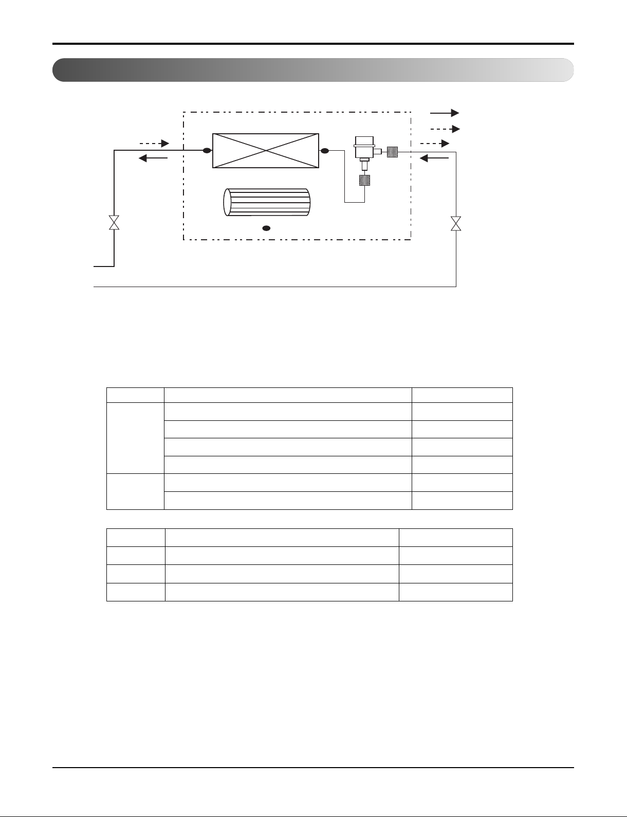
4. EEV: Electronic Expansion Valve
5. To be added for more available Models
Conversion Formula
kcal/h= kW x 860
Btu/h = kW x 3412
cfm = m3/min x 35.3
l/s = CMM x 1000/60
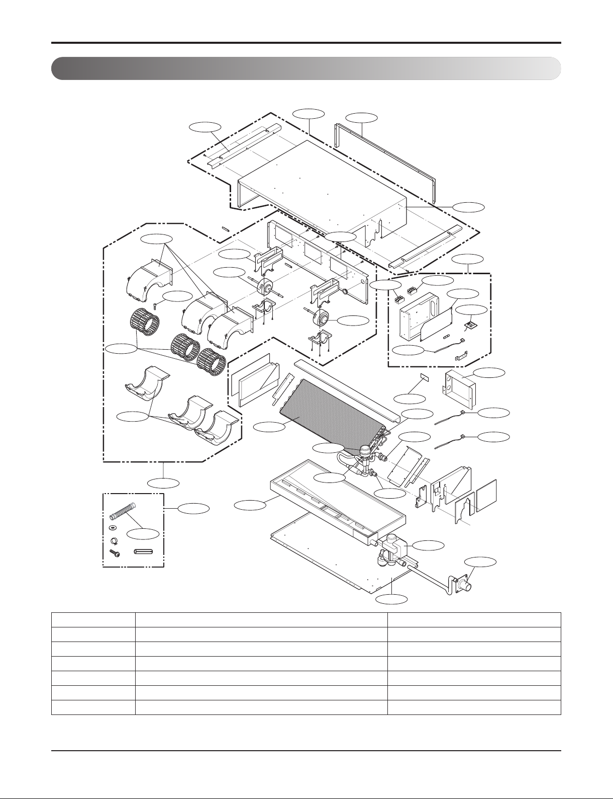
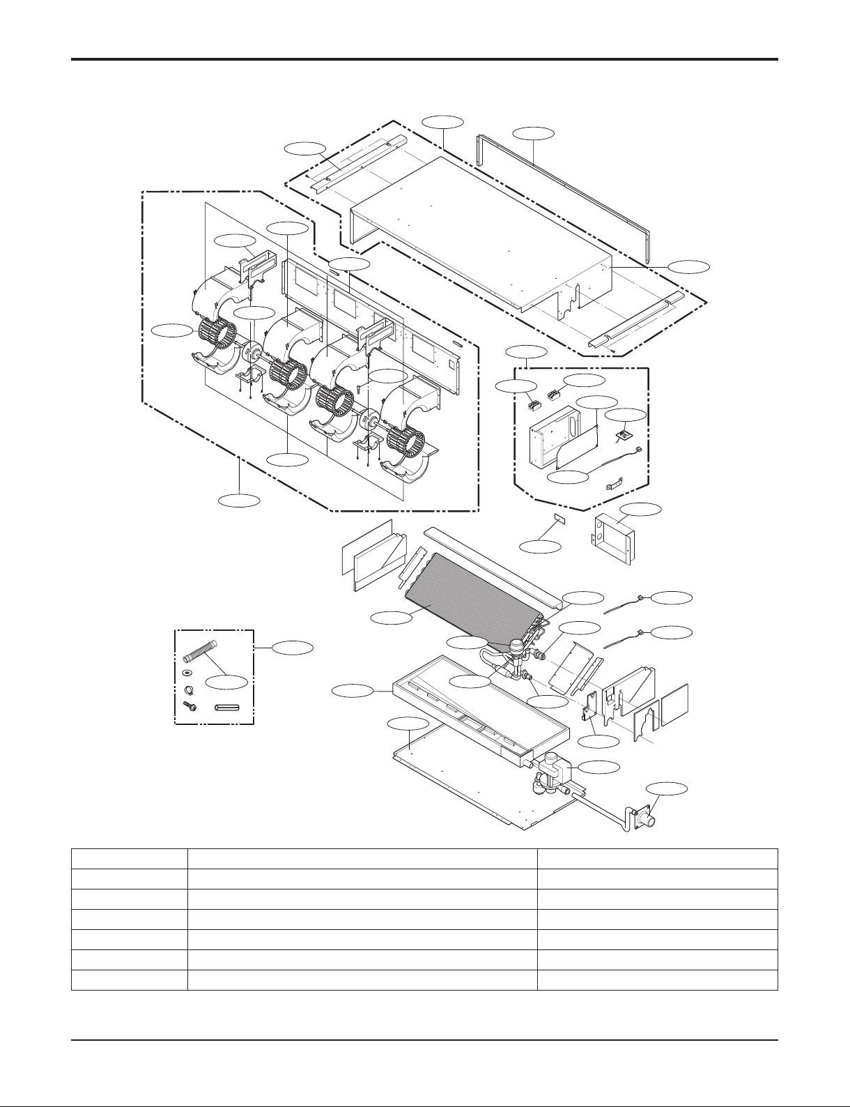
Type Ceiling Concealed Duct (Built-in)
Accessory PBSGB30/PBSC30 PBSGB40/PBSC40 PBSGB40/PBSC40
Model Unit ARNU15GB3G4 ARNU18GB4G4 ARNU24GB4G4
Cooling Capacity
kW 4.5 5.6 7.1
kcal/h 3,900 4,800 6,100
Btu/h 15,400 19,100 24,200
Heating Capacity
kW 5 6.3 8
kcal/h 4,300 5,400 6,900
Btu/h 17,100 21,500 27,300
Casing Galvanized Steel Plate Galvanized Steel Plate Galvanized Steel Plate
Dimensions
(WxHxD) Body mm 820 x 190 x 575 1,100 x 190 x 575 1,100 x 190 x 575
inch
32-9/32 x 7-15/32 x 22-5/8 43-5/16 x 7-15/32 x 22-5/8 43-5/16 x 7-15/32 x 22-5/8
Coil Rows x Columns x FPI 2 x 11 x 21 3 x 10 x 18 3 x 10 x 18
Face Area m30.16 0.23 0.23
Fan
Type Sirocco Fan Sirocco Fan Sirocco Fan
Motor Output x Number
W 19 x 1, 5 x 1 19 x 2 19 x 2
Running Current A 0.76 0.97 0.97
Air Flow Rate(H / M / L)
(High Mode-factor set)
External Static Pressure
CMM 11.0 / 10.0 / 8.0 14.0 / 12.0 / 10.0 17.0 / 15.0 / 10.0
cfm 388 / 353 / 283 494 / 424 / 353 600 / 530 / 353
mmAq(Pa) 2(20) 2(20) 2(20)
Air Flow Rate(H / M / L)
(Standard Mode)
External Static Pressure
CMM 11.0 / 10.0 / 8.0 14.0 / 12.0 / 10.0 17.0 / 15.0 / 10.0
cfm 388 / 353 / 283 494 / 424 / 353 600 / 530 / 353
mmAq(Pa) 0(0) 0(0) 0(0)
Drive Direct Direct Direct
Motor type BLDC BLDC BLDC
Temperature Control
Microprocessor, Thermostat
for cooling and heating
Microprocessor, Thermostat
for cooling and heating
Microprocessor, Thermostat
for cooling and heating
Sound Absorbing Thermal Insulation Material Foamed polystrene Foamed polystrene Foamed polystrene
Air Filter - - -
Safety Device
Fuse, Thermal Fuse for Fan Motor Fuse, Thermal Fuse for Fan Motor Fuse, Thermal Fuse for Fan Motor
Pipe Connections
Liquid Side mm(inch) Ø6.35(1/4) Ø6.35(1/4) Ø9.52(3/8)
Gas Side mm(inch) Ø12.7(1/2) Ø12.7(1/2) Ø15.88(5/8)
Drain Pipe(Internal Dia.)
mm(inch) 25.4(1) 25.4(1) 25.4(1)
Net Weight kg(lbs) 21(46.3) 26(57.3) 26(57.3)
Noise Level(Sound Press, 1m, H / M / L) dB(A) 41 / 40 / 37 43 / 40 / 37 46 / 43 / 37
Power Supply Ø, V, Hz 1, 220-240, 50 1, 220-240, 50 1, 220-240, 50
1, 220, 60 1, 220, 60 1, 220, 60
Refrigerant Control EEV EEV EEV
Power cable mm2CV1.5 x 3C CV1.5 x 3C CV1.5 x 3C
Transmission cable mm2CVV-SB 1.0~1.5 x 2C CVV-SB 1.0~1.5 x 2C CVV-SB 1.0~1.5 x 2C


 null")