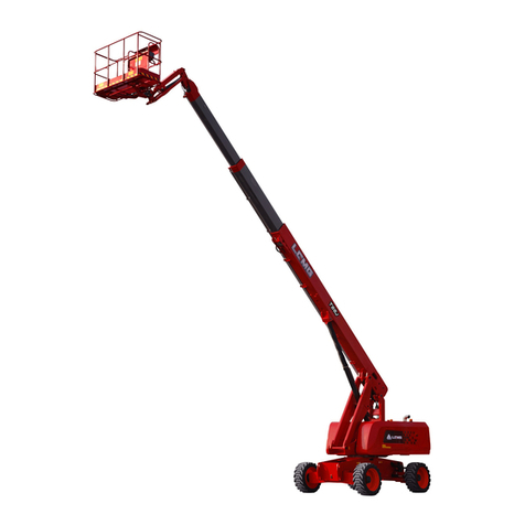
LGMG SR0818D User manual

Maintenance Manual
SR0818D/SR1018D/SR1218D
SR1023D/SR1323D/SR1623D
Rough Terrain
Mobile Elevating work platform
△
!Warning
Before operation and maintenance, the
drivers and service personnel shall
always read and thoroughly understand
all information in this manual. Failure to
do so may result in, fatal accidents or
personal injury.
This manual must be kept with this
machine at all times.
LINGONG HEAVY MACHINERY CO., LTD.

Rough Terrain Mobile Elevating Work platform
Maintenance Manual
880*1230 mm 16 format 8 printed sheets
Third edition and printed for the first time in July 2022
L i n go n g H ea v y M a c h i ne r y C o . , L t d .
Add: 12th Floor, Building 3, Lushangguoaocheng, 9777 Jingshi Road, Lixia District, Jinan,
China
Tel: 86-0531-67605017 Fax: 86-0531-67605017
Technical service: 86-0531-67605017 Web: www.LGMG.com.cn
Accessories sales: 86-0531-67605016

Maintenance Manual of Rough Terrain
Mobile Elevating Work Platform
I
Contents
Contents.......................................................................................................I
Forward.......................................................................................................II
Safety Attentions........................................................................................III
Chapter 1 Maintenance...............................................................................1
1.1 Compliance and obedience .............................................................. 3
1.2 Check for safety manual................................................................... 3
1.3 Check for labels and signs................................................................ 3
1.4 Check for damaged, loose or missing parts...................................... 3
1.5 Check for PCU and GCU.................................................................. 4
1.6 Check for wires................................................................................. 4
1.7 Check for batteries............................................................................ 5
1.8 Check for tires and hubs................................................................... 6
1.9 Check for exhaust cover of hydraulic oil tank.................................... 6
1.10 Check for hydraulic oil leakage....................................................... 7
1.11 Check for the Hydraulic Filter.......................................................... 7
1.12 Replacement of the air filter of the hydraulic oil tank....................... 8
1.13 Check hydraulic oil level ................................................................. 8
1.14 Inspect or replacement of hydraulic oil............................................ 8
1.15 Check for the oil level in the reducer............................................... 9
1.16 Replacement of the gear oil of reducer........................................... 9
1.17 Engine maintenance –Deutz......................................................... 10
1.18 Engine maintenance-Kubota......................................................... 16
1.19 Check or replacement of scissors arms slider............................... 22
1.20 Regular maintenance.................................................................... 24
1.21 Engine fault table.......................................................................... 24
1.22 Engine fault code.......................................................................... 31
Chapter 2 Schematics...............................................................................39

Maintenance Manual of Rough Terrain
Mobile Elevating Work Platform
II
Forward
Thanks for choosing elevating work platforms manufactured by Lingong Heavy Machinery Co., Ltd. This
machine is designed according to AS/NZS1418.10:2011+A1:2017. This manual describes the
mechanism, driving and operation, maintenance and adjustment, technical parameters and
repair/adjustment data of the elevating work platforms.
Maximizing the profits from your elevating work platform is our common goal, which is largely dependent
on your familiarity with the platform and careful and thorough maintenance. We sincerely hope that you
can read through the manual prior to the first start, operation as well as repair and maintenance of the
platform and get full understanding of the operations and maintenances described herein.
All the pictures and descriptions covered herein are correct at time of publication; but the structures and
performances of our products are constantly improved and perfected; therefore, please understand that
the related design, operation and maintenance instructions are subject to change at any time without
prior notice. For the latest information on the elevating work platform or in case of any doubt about this
manual, please consult LGMG.
This manual is applicable for elevating work platforms. Users shall be in strict accordance with the time
interval in the maintenance schedule to perform maintenance to the platform.
This manual shall always be placed at the specified position so that the driver can read it at any time.
This manual is a part of the elevating work platform and thus shall be handed over together when
transferring the ownership or the right to use of the platform. If this manual is lost, damaged or hard to be
recognized, please replace it in time!
The copyright of this manual is reserved by Lingong Heavy Machinery Co., Ltd. Reproduction or
reprinting without written permission by LGMG is prohibited.
△
!Warning
Only the specially trained staff with corresponding qualifications is allowed to
operate, repair and maintain the platform.
Incorrect operation, maintenance and repair are dangerous, and may lead to
personal injury.
Before operation or maintenance, the operator shall carefully read this manual.
Do not operate, maintain, and repair this platform without reading and
understanding this manual.
Loading shall be done in strict accordance with the rated loading capacity, and
any consequence due to overloading or unauthorized modification shall be the
responsibility of the users.
The operation procedures and precautions referred to herein are only applicable
to the stipulated operation of the machine. For any operation out of the
specification but not prohibited, always make sure that this operation will not
hurt you or other people.

Maintenance Manual of Rough Terrain
Mobile Elevating Work Platform
III
Safety Attentions
Operators shall understand and follow prevailing national and local safety regulations. In case of no
relevant national or local regulation, safety attentions in this manual will be applicable.
Most accidents are caused by failure of following regulations on machine operation and maintenance. To
avoid accident, please read, understand and follow all warning requirements and notes in this manual
and on the machine before operation and maintenance.
Since it is unable to predict all possible dangers, therefore, safety explanation in the manual and on the
machine may not include all safety precautions. If the procedures and operation which are not
recommended in this manual are used, it must ensure people's safety and have no damage on
machines. If the user cannot confirm the safety of some operations, please ask the Company or the
dealer.
The prevention measures on operation and maintenance given in this manual are only applicable to use
of the machine as per the regulations. If the machine is used in the scope which is not listed in this
manual, the Company will not undertake any safety liability. The safety liabilities of this operation are
undertaken by users and operators.
The operation forbidden in this manual cannot be performed in any condition.
The following markers are used for identifying the safety information in this manual:
△
!Danger:
Due to failure to avoid it, the sequence of the danger will cause serious injuries or
death. This word also indicates that failure to avoid it may cause serious damages to
the machine.
△
!Warning:
Due to failure to avoid it, the sequence of potential danger may cause serious
injuries or death. This word also indicates that failure to avoid it may cause serious
damages to the machine.
△
!Notice:
Failure to avoid it may cause light or medium injuries. This word also indicates that
failure to avoid it may cause damages to the machine or shortening of the service life
of the machine.

Maintenance Manual of Rough Terrain
Mobile Elevating Work Platform
IV

Maintenance Manual of Rough Terrain
Mobile Elevating Work Platform
1
Chapter 1 Maintenance

Maintenance Manual of Rough Terrain
Mobile Elevating Work Platform
2

Maintenance Manual of Rough Terrain
Mobile Elevating Work Platform
3
1.1 Compliance and
obedience
1) The operator is only allowed to perform
routine maintenance items as specified in
this manual.
2) Carry out periodic maintenance and check
by trained maintenance technicians as
required by the manufacturer.
Maintenance Symbols
The following symbols are used in this manual
to help convey relevant meanings in the
instructions. When one or more symbols are
shown at the first part of the maintenance
program, the meanings expressed are as
follows.
It indicates a tool required to carry out this
procedure.
It indicates a new part required to carry out this
procedure.
It indicates that the engine must be in a cooling
state before carrying out this procedure.
1.2 Check for safety manual
It is required to keep the operator in a good
state and the safety manual in proper condition
for safe operation. The manual shall be stored
in a container in the working platform provided
by each machine. An unrecognized or lost
manual shall be unable to provide necessary
safety and operation information for safe
operation.
1) Confirm that the storage container is on site
and in a good condition.
2) Confirm both the responsibility manual and
safety manual are in the storage container
within the work platform by the operator.
3) Check each page of the manual to be
legible and in a good condition.
4) Put the manual into the file storage box
after use.
△
!If the manual needs to be replaced,
please contact the service staff of
LGMG.
1.3 Check for labels and
signs
It is required to keep all safety and description
labels and signs in a good condition for safe
operation of the platform. Labels warn operators
and staff of many possible hazards in using the
platform. They also provide users with operation
and maintenance information. Illegible labels
cannot warn staff of steps or hazards and may
lead to unsafe operating conditions.
Refer to the label section in this operation
manual and use the label menu and instructions
to check that all labels are in place.
Check the clarity and damage of all the labels
and immediately replace any damaged or
illegible label.
△
! If the labels need to be replaced,
please contact the service staff of
LGMG.
1.4 Check for damaged,
loose or missing parts
This step is performed every 8 hours or every
day. whichever comes first.
Carrying out daily equipment status check is
necessary for ensuring safe equipment
operation and maintaining good equipment
performance. Incorrect positioning, repairing
damaged equipment, and loose or missing parts
may result in unsafe operating conditions.
1) Check for damaged parts for the whole
platform, and check for incorrect installation
or missing parts and components,
including:

Maintenance Manual of Rough Terrain
Mobile Elevating Work Platform
4
Electrical components, wirings and cables
Hydraulic hoses, connectors, valve blocks
and hydraulic cylinders
Fuel and hydraulic tanks
Wear-resistant pads
Tires and wheels
Engine and related components
Limit switch and horn
Nuts, bolts and other fasteners
Platform extension components
Platform entrance door
Indicators and alarms
Safety arm
Scissors arms pin and fastener
Platform control handle
Outrigger cover and foot pad
2) Check the entire machine for:
Cracks in welds or structural components
Whether the platform, fork frame and
chassis are deformed or have cracked weld
joints.
Indentation or damage to the machine
Ensure that all structural components and
other key components are complete and all
relevant fasteners and pins are in the
correct position and tightened.
Ensure that the guardrail has been installed,
and guardrail bolts have been properly
installed and tightened.
△
!Notice: If the platform must be
raised to check the machine, ensure
that the safety arm is in the correct
position. See the "Operation
Instructions" section.
1.5 Check for PCU and GCU
This step is performed every 8 hours or every
day, whichever comes first.
The functions of the test equipment and the red
emergency shutdown switch are required for
safe operation of the platform. If there is an
unsafe working condition or any normal
operation failure, the red emergency shutdown
switch will disable all functions and shut down
the engine. Each function shall be enabled for
smooth operation without any pause, jitter or
abnormal noise.
1) Pull out the red emergency shutdown
switches on the GCU and PCU.
2) Turn the key switch to GCU. Start the
engine.
3) It is strictly forbidden to press the lift
enabling switch and try to turn on each
function switch.
Result: Operation of all functions shall be
forbidden.
4) Press and hold the lift enabling switch to
turn on each function switch.
Result: All functions shall be performed for a full
cycle. The buzzer shall sound when the platform
falls down.
5) Push the red emergency shutdown switch
button on the GCU to the "Off" position.
Result: The engine shall be shut down and all
functions shall be disabled.
6) Turn the key switch to the operation
platform control unit, and pull out the red
emergency shutdown switch to the "On"
position on the GCU.
7) Start the engine through the work platform.
8) It is strictly forbidden to press the function
enabling switch and try to perform all
platform functions.
Result: Operation of all platform functions shall
be forbidden.
9) Press and hold the function enabling switch.
Try to perform all platform functions.
Result: All platform functions shall be performed
for a full cycle.
10) Push the red emergency shutdown switch
button on the PCU to the "Off" position.
Result: The engine shall be shut down and all
functions shall be disabled.
1.6 Check for wires
This check should be performed every 250 h or
quarterly, whichever comes first.
1) Keeping wires in a good condition is critical
for safe operation and good performance of
the platform. Failure to find and replace
wires burned, scratched, corroded or bent
will result in unsafe operating conditions or
even cause damage to platform parts.

Maintenance Manual of Rough Terrain
Mobile Elevating Work Platform
5
Electric Shock/Explosion Hazards
△
!Danger: Thermal contact or live
conductors may lead to serious
casualty accidents. Do not wear rings,
watches or other jewelry.
1) Check if the ground wires under the chassis
are missing or damaged.
2) Check the following areas for wires burned,
scratched, corroded, bent or loosened:
Interior of GCU box
Hydraulic valve group wires
Battery wires
Interior of PCU box
3) Turn the key switch to the PCU and pull out
the red emergency shutdown switches on
the GCU and PCU.
4) Raise the platform to a height which is
about 4 m away from the ground.
5) Lift the safety arm and move it to the middle
of scissors axle sleeve, revolve it upward
until it is vertical.
6) Lower the platform height until the safety
arm contacts the axle sleeve completely.
Smashing and Pressing Hazards
△
!Warning: When the platform is
lowered, make sure the operator's
hand is in the correct position of the
safety arm.
1) Check the chassis and scissors area for
wires burned, scratched, corroded, bent or
loosened:
2) Check the following areas for wires burned,
scratched, corroded, bent or loosened:
Scissors arm wire
ECU to platform
Harness connectors connected to the
platform
3) Check the free coating of insulating oil in
the following locations:
Harness connectors connecting the ECU
with PCU
Level sensors
All wire harness connectors
4) Ascend the platform and restore the safety
arm to the installation position.
5) Shut down the machine after descending
the platform to the folding position.
1.7 Check for batteries
Keep away from fireworks and remove all
rings, watches and other accessories. Wear
goggles, protective gloves and protective
clothing if necessary. Avoid touching the
spilled electrolyte with hands or other parts of
the body. Neutralize with baking soda and
the spilled electrolyte.
Good battery condition is essential for
machine performance and safe operation.
Improper voltage or damaged cables and
wiring may cause component damage and
dangerous situations.
Maintenance-free lead-acid battery
inspection:
Check that the battery locking lever is
secure
Check the wiring of the battery cable.
The wiring is firm and free from
corrosion.
Check whether the battery fluid leaks
and whether the battery is dry and clean.
Check the status of the electric eye every
three months (maintenance free lead-acid
battery).
Check the color of the battery hydrometer as
shown in the figure:
Battery hydrometer
Hydrometer
color
Meaning and treatment
White
Lack of battery fluid. Please shut
down the machine and stop
using it
Black
Power loss or damage

Maintenance Manual of Rough Terrain
Mobile Elevating Work Platform
6
Green
Measure the voltage of each
battery. If the voltage is lower
than 11V, it indicates that the
battery is damaged; The voltage
is between 12.4v-12.7, indicating
that the battery is in good
condition
If the color of the battery hydrometer is
green and the voltage is above 12V, but
the starter cannot be driven, please ask
the personnel trained and qualified for
the maintenance of the machine to
further test the battery.
Battery recharge:
Before charging, disconnect the
negative connection of the battery first,
and then the positive connection of the
battery.
Before replenishing electricity, clean the
end column and remove the oxide scale
on the surface.
△
!Note: If an external power
supply is required to charge the
battery, only the charger approved
by the LGMG can be used.
Do not replenish the battery with
white eyes. Replace the battery.
When wiring after charging,
connect the positive wire first and
then the negative wire.
△
! Notice: Adding a terminal
protector and an anti-corrosion sealant
will help remove corrosion caused to
battery terminals and cables.
1.8 Check for tires and hubs
This check item is conducted every 200 hours or
two month, whichever comes first.
Keeping tires and hubs in a good condition is
critical for safe operation and good performance.
Failure of the tires and hubs may cause the
platform to tilt. If such failure is not found and
repaired in time, it will also cause damage to
platform parts.
1) Check treads and sides of tires for scratches,
cracks, punctures, and other abnormal
wear.
2) Check if the hubs are damaged, bent or
cracked.
3) Check whether or not the technological
screws for tires are detached. Upon the
detaching of screws, if there is slight or no
leakage of fillers, and no significant
deformation is found for the tire body, and
users can knock in screws which are
slightly larger than the diameter (about
5mm) of the vent hole with a hammer. If
leakage of a large quantity of fillers is found,
and the tire body deforms significantly, it is
necessary to reduce the height of the
working platform and replace the tires
timely.
4) Check for nut torque of tires:305±25N.m
1.9 Check for exhaust cover
of hydraulic oil tank
1) This check item shall be conducted every
250 hours or quarterly, whichever comes
first.
2) An unobstructed hydraulic oil tank cap is
essential for good mechanical performance
and long service life of the platform. A dirty
or clogged exhaust cover may result in poor
platform performance. Given harsh working
environment, more frequent check is
required.
①Remove the exhaust cover from the
hydraulic oil tank cap.
②Check for ventilation.
Result: Air can pass through the exhaust cover.
Result: If air does not pass through the exhaust
cover, clean or replace the exhaust cover.
Continue with Step 3.
△
!Notice: Air is supposed to pass
freely while checking ventilation of the
oil tank cap.
○
3Carefully clean the tank exhaust cover with
mild solvent and dry it with low pressure
compressed air. Repeat Step 2.

Maintenance Manual of Rough Terrain
Mobile Elevating Work Platform
7
3) Install the exhaust cover of the hydraulic oil
tank.
1.10 Check for hydraulic oil
leakage
Check leakage every 8 hours or once a day.
△
! Danger of personal injury.
Sputtered hydraulic oil may penetrate
and burn the skin.
Check for residues of hydraulic oil, oil droplets
or oil in the following areas:
All hydraulic cylinders.
Each valve element
Each oil pipe and connector
Walking motor
Reducer
Filter
Hydraulic oil tank
Hydraulic pump
Under the chassis
Shaft
Ground area under the platform.
1.11 Check for the Hydraulic
Filter
Check or replace it every 500 hours or half a
year.
△
! If the work environment is dusty,
increase the number of times that
perform this step.
It is necessary to replace the hydraulic
filter to maintain good machine
performance and service life. Dirty or
blocked filters may cause a decrease
in machine performance and
continuous use may result in damage
to components. An increase in the
number of replacement filters is
required for the extremely dirty
working condition.
△
! Danger of personal injury.
Be careful with hot oil, and contact
with them will lead to severe burn.
△
! Perform this step when the
engine is turned off.
Replacement of the Return Oil Filter
Element of Hydraulic Oil Tank
1) This step shall be performed every 500
hours or half a year, whichever comes first.
2) It is crucial to replace the return oil filter
element for the good performance and
service life of the machine. Dirty or blocked
filters may affect machine performance and
continuous use shall result in damage to
components. The filter elements should be
replaced more frequently under the poor
working condition.
Be careful: danger of scald
Watch out for hot oil. Contact with hot oil
may cause severe burn.
①Open the cover above the oil tank.
②Remove the filter element flange above the
oil tank.
③Put the filter element out and replace the
new filter element.
④Install flange and cover plate.
⑤Note down the replacement time and date
on the filter element replacement table
using a marker.
⑥Turn the key switch to the GCU, and pull
out the red emergency shutdown button on
the GCU and PCU.
⑦Press the lifting function button.
⑧Check the filter components for oil leakage.
Replacement of High-Pressure Filter
Element
1) Place an appropriate container under the

Maintenance Manual of Rough Terrain
Mobile Elevating Work Platform
8
filter.
2) Remove the nuts at the bottom of the filter
cover with a wrench and remove the filter
cover.
3) Remove the filter element from the filter
cover.
4) Check the seal of filter cover and replace it
if necessary.
5) Install the new high-pressure filter element
and tighten it.
6) Scrub out any oil droplet that is splashed
out during installation.
7) Check the filter cover and the associated
elements to ensure no leakage.
1.12 Replacement of the air
filter of the hydraulic oil tank
Replace it every 500 hours or half a year, and
increase the number of times that perform this
step if the work environment is too dusty.
△
! Perform this step when the
engine is turned off.
1) Remove the filter element.
2) Scrub out the inside and tail cover of the
tank with a piece of damp cloth.
3) Install a new air filter element.
1.13 Check hydraulic oil level
Check it every 8 hours or every day.
It is crucial for the machine to keep the hydraulic
oil at a suitable oil level. The hydraulic oil at an
inappropriate level will damage the hydraulic
components. Through routine inspection, the
inspector can determine the change of hydraulic
oil level, which can indicate the problems of
hydraulic system.
△
! Notice: Perform this procedure
when the platform is in a folding state
and the engine is closed.
1) Park the vehicle on a flat ground. The
platform is in a folding state.
2) Check the oil pointer on the hydraulic oil
tank. When the fork frame is in the folding
state, the hydraulic oil level should be
locked in the 1/2 - 2/3 of the liquid level
meter (Short oil level gauge) or “LH”
position of the liquid level meter (long oil
level gauge), and fill the hydraulic oil if
necessary.
Condition
Oil viscosity brand
-25℃<The lowest
temperature
L-HV 32 low
temperature
hydraulic oil
-40℃<The lowest
temperature≤-25℃
L-HS 32 Ultralow
temperature
hydraulic oil
The lowest
temperature≤-40℃
10# Aviation
hydraulic oil
1.14 Inspect or replacement
of hydraulic oil
Replace the hydraulic oil every 2000 hours or
two years, whichever comes first.
△
! If the hydraulic oil is not replaced
during the two-year inspection, check
the hydraulic oil quarterly. Replace it
when the test is not qualified.
△
! Perform this step when the arm
lever is in the folding state.
△
! When removing the hose
assembly or couplers, the O-rings or
hose ends on the coupler must be
replaced and tightened to the specified
torque during installation.
Close two ball valves located on the hydraulic
oil tank (if the ball valve has been equipped).
△
!Hazard of damage to components.
The engine cannot be started when the
ball valve of the hydraulic oil tank is
closed, otherwise the components will
be damaged. If the ball valve is closed,
remove the key from the key switch
and hang a warning sign on the

Maintenance Manual of Rough Terrain
Mobile Elevating Work Platform
9
equipment.
1) Remove oil drain plug, ring magnet, and oil
drain flange from the hydraulic oil tank.
2) Drain the hydraulic oil from the hydraulic oil
tank completely into a suitable container.
3) Disconnect the hose connected to the oil
tank and protect the hose coupler to
prevent foreign matter from entering.
4) Remove the fixed fasteners from hydraulic
oil tank.
5) Remove the hydraulic oil tank from the
equipment.
6) Remove the adsorption filter screen from
the hydraulic oil tank and clean it with a
mild volume.
7) Flush the inside of hydraulic oil tank with
mild solvent.
8) Clean the foreign matters adsorbed by ring
magnets.
9) Install adsorption filter screen.
10) Install oil drain plug. Ring magnet and oil
drain flange.
11) Install the hydraulic oil tank on the
equipment.
12) Install hose.
13) Fill the hydraulic oil to the hydraulic oil tank
until the liquid level is locked in the 1/2 - 2/3
of the liquid level meter (Short oil level
gauge) or “LH”position of the liquid level
meter (long oil level gauge), and it is
forbidden to overflow.
14) Scrub off the hydraulic oil that may be
sprayed out.
15) Open the ball valve on the hydraulic oil
tank.
△
! Danger of damage to components,
after installing the hydraulic oil
tank, make sure to open two ball
valves of the hydraulic oil tank and
fill the pump with oil.
16) Check the functions of all machines through
an entire cycle and check for oil leakage.
17) Recheck the tank level after a cycle and
refuel to the specified position.
1.15 Check for the oil level in
the reducer
Check this step every 250 hours or a quarter.
The incorrect oil level in the reducer shall lead to
the reduction of equipment performance and
continuous use will result in damage to
components.
1) Drive the equipment rotating until a plug is
at the highest point, and the other is about
90 degrees from this one.
2) Remove the plug at 90 degrees and check
the oil level.
Result: The oil level shall be the same as the
bottom of the side plug hole.
3) When required, remove the upper plug and
refill oil until the oil level is the same as the
bottom of the side plug hole.
4) Apply the pipe thread sealant to the plug
and install the plug in the reducer.
5) Repeat this step for each reducer.
Condition
Oil viscosity brand
API GL-5
30°C<The lowest
temperature
85W/140
-10°C<The lowest
temperature<30°C
85W/90
-30°C<The lowest
temperature<-10°C
80W/90
The lowest
temperature<-30°C
75W
1.16 Replacement of the gear
oil of reducer
It is available in the first 50 hours, and it will be
replaced every 1000 hours or a year.
It is necessary to replace the gear oil of reducer
to maintain good equipment performance and
service life. Failure to replace the reducer oil
every year may result in reduced equipment
performance, and continuous use may result in
damage to components.
1) Select the reducer to be maintained, and
drive the equipment until one plug is at the
lowest point.
2) Remove the two plugs and drain the oil
(note to be drained) into the proper
container.

Maintenance Manual of Rough Terrain
Mobile Elevating Work Platform
10
3) Drive the equipment rotating until a plug is
at the highest point, and the other is 90
degrees from this one.
4) Refill oil from the hole of reducer at the high
point until the liquid level is the same as the
side hole at the bottom. Install a plug.
5) Repeat this procedure for each reducer to
refuel.
1.17 Engine maintenance –
Deutz
1.17.1 Check for engine oil
level
△
! Do not operate on running
engines!
No smoking and open fires!
Be careful when contacting with high
temperature engine oil. Danger of
scalding!
△
! When operating on the oil system,
pay attention to the surface cleaning.
Carefully clean all areas involved. Blow
wet parts with compressed air.
△
! Please observe the safety
regulations for engine oil and relevant
local regulations. Dispose of spilled
engine oil and filter elements as
required. Waste oil cannot penetrate
into the ground.
△
!Test run shall be carried out after
each operation. At the same time, pay
attention to the sealing and lubricating
oil pressure, and then check the
engine oil level.
Check the engine oil level every 8 hours or
every day.
Insufficient or excessive engine oil may cause
damage to the engine. The engine oil level can
only be checked when the engine is placed
horizontally and closed. If the engine is hot,
close the engine and check the engine oil level
5 minutes later. Check it immediately if the
engine is cooled.
1) Insert the oil measuring rod and clean it
with a piece of clean and fiber-free cloth.
2) Insert the oil measuring rod into the bottom.
3) Pull out the oil measuring rod and read the
value of engine oil level.
4) The engine oil level shall always be
between MIN and MAX!
5) Fill up to the maximum liquid level if
necessary.
1.17.2 Replacement of engine
oil and filter
△
! Do not operate on running
engines!
No smoking and open fires!
Be careful when contacting with high
temperature engine oil. Danger of
scalding!
△
!When operating on the oil system,
pay attention to the surface cleaning.
Carefully clean all areas involved.
Blow wet parts with compressed air.
△
! Please observe the safety
regulations for engine oil and relevant
local regulations. Dispose of spilled
engine oil and filter elements as
required. Waste oil cannot penetrate
into the ground.
△
! Test run shall be carried out after
each operation. At the same time, pay
attention to the sealing and lubrication

Maintenance Manual of Rough Terrain
Mobile Elevating Work Platform
11
oil pressure, and then check the
engine oil level.
It is available in the first 50 hours, and the
engine oil and filter shall be replaced every 500
hours or half a year. (If the ambient temperature
continues to be below -10℃. (14゜F) or the
temperature of engine oil is below 60℃(84゜F),
or the sulphur content in the diesel fuel is 0.5 -
1%, the oil change period is reduced by a half; if
the engine oil does not reach the replacement
interval period within a year, the oil shall be
replaced at least once a year.)
△
! Danger of burn, be careful of
high-temperature engine parts and oil,
contacting with high temperature
engine oil and/or engine parts will
cause severe burns.
△
! Perform the function after engine
warm up to normal operation
temperature.
Replacement of engine oil
1) Warm up and run the engine .
2) Place the engine horizontally.
3) Shut down the engine.
4) Place the container under the engine oil
drain plug.
5) Screw off the engine oil drain plug to drain
the old engine oil.
6) Install the new seal ring for the engine oil
drain plug and screw in and tighten it.
7) Add engine oil at the engine oil filler.
8) Warm up and run the engine.
9) Place the engine horizontally.
10) Check the engine oil level and fill it if
necessary.
Replacement of the engine oil filter
The engine oil filter element must also be
replaced every time the engine oil is replaced.
△
!Never fill the filter in advance.
There is risk of contamination.
1) If a torsion stopper is installed, remove the
clamping clamp (optional).
2) Release and unscrew the filter element with
a wrench.
3) Contain the oil that was drained.
4) Clean the sealing surface of the filter holder
with a clean fiber-free wiper.
5) Apply a thin layer of engine oil to the seal
ring of the new filter.
6) Screw in a new filter manually until seal fit
and tighten it with 10-12 Nm.
Tighten the torque.
7) Fix the clamping clamp of a torsion stopper
(optional).
1.17.3 Check for fuel leakage
△
! The engine must be shut down!
No smoking and open fires!
Be careful when contacting high
temperature fuel!
Please observe the safety regulations
for fuel and relevant local regulations.
Dispose of spilled fuel and filter
elements in accordance with national
regulations. The fuel cannot seep into
the ground.
Visually check for fuel leakage every 8

Maintenance Manual of Rough Terrain
Mobile Elevating Work Platform
12
hours or every day.
△
! There is danger of explosion and
fire. The fuel of the engine is
combustible. Check the position of the
machine. When this step is performed,
the machine shall be away from the
heater, spark, flame, and open and
well-ventilated areas with burning
tobacco. A qualified fire extinguisher
shall be placed in an easily accessible
place.
△
! There is danger of explosion and
fire. If fuel leaks, prevent any additional
person from entering the area or
operating the equipment. Repair the
leakage immediately.
1.17.4 Vent Fuel Pre-Filter
△
! Risk of explosion and fire. Engine
fuel is combustible. The position
where the equipment is located shall
be inspected. When the step is
executed, equipment shall be located
in an open and well-ventilated area that
keeps away from the heater, spark,
flame and burning tobacco. A qualified
fire extinguisher shall be placed at the
location that is easily accessible.
△
!Perform the step when the engine
flames out.
1. Fuel supply flow to the pump
2. Venting screw
3 .Electrical connection for water level sensor
4. Drain plug
5. Filter insert
6. Fuel inlet from the fuel tank
Check and drain the fuel filter every 8 hours or
every day.
1) Shut down the engine, and find the fuel
filter.
2) Disconnect cable connection.
3) Loosen the drainage plug located at the
bottom of the filter cartridge, allowing the
water drained to an appropriate container.
Once any fuel starts to flow out, screw
down the drainage plug immediately.
4) Wipe up any fuel that may be splashed.
5) Start the engine from the ground control
and inspect whether or not there is leakage
in the fuel filter.
Change the fuel pre-filter insert
1) Switch off the engine.
2) Shut off the fuel supply to the engine (with
high-level tank).
3) Place suitable collecting containers
underneath.
4) Disconnect cable connections.
5) Loosen drain plug and drain liquid.
6) Disassemble filter insert.
7) Clean any dirt of the opposite side of filter

Maintenance Manual of Rough Terrain
Mobile Elevating Work Platform
13
head.
8) Wet the sealing surfaces of the filter
cartridge slightly with fuel and screw back
on to the filter head, clockwise (17-18 Nm).
9) Mount drain plug.
10) Open the fuel shutoff tap and vent the
system, see venting the fuel system.
Vent the fuel system
The fuel system is vented via the electric fuel
supply pump.
In order to ensure that no error messages are
generated, no attempt should be made to start
the system up whilst venting.
This process is carried out as follows:
● Ignition "ON"
The electronic fuel supply pump switches on for
20 seconds in order to vent the fuel system and
build up the required fuel pressure.
Wait until the electric fuel supply pump is
disconnected from the control unit.
● Ignition "OFF"
Repeat the process at least 2 times until the fuel
system is vented
△
!Risk of explosion and fire. Where
there is fuel leakage, prevent any
irrelevant personnel from entering the
area and strictly prohibit operating the
equipment. Repair the leak
immediately.
1.17.5 Replacement of the fuel
filter element
△
! The engine must be shut down!
No smoking and open fires!
Be careful when contacting high
temperature fuel!
△
! Do not release the injection
pipeline or the high-pressure oil
pipeline when the engine is running.
△
! Carefully clean all areas involved
in cleaning. Blow wet parts with
compressed air.
△
! Please observe the safety
regulations for fuel and relevant local
regulations. Dispose of spilled fuel and
filter elements in accordance with
national regulations. The fuel cannot
seep into the ground.
△
! After completing the operation on
the fuel system, exhaust the system,
perform the trial operation and check
the seal performance.
It is available in the first 50 hours, and
it will be replaced every 500 hours, or a
quarter, but an increase in the number
of replacement filters is required for
the extremely dirty work environment.
△
! There is danger of explosion and
fire. The fuel of the engine is
combustible. Check the position of the
machine execution.
When this step is performed, the
machine shall be away from the heater,
spark, flame, and open and
well-ventilated areas with burning
tobacco.
A qualified fire extinguisher shall be
placed in an easily accessible place.
△
! Never fill the filter in advance.
There is risk of contamination.

Maintenance Manual of Rough Terrain
Mobile Elevating Work Platform
14
1) If a torsion stopper is installed, remove the
clamping clamp (optional).
2) Release and unscrew the filter element with
a wrench.
3) Contain the diesel fuel drained.
4) Clean the sealing surface of the filter holder
with a clean fiber-free wiper.
5) Apply a thin layer of diesel to the seal ring
of the new filter.
6) Screw in a new filter manually until seal fit
and tighten it with 10-12 Nm.
7) Tighten the torque.
8) Fix the clamping clamp of a torsion stopper
(optional).
9) Exhaust the fuel system.
1.17.6 Check for engine air
filter
Check the maintenance indicator (If equipped)
for the air filter every 8 hours or every day.
Check the maintenance indicator for the air filter
△
!Perform this step when the engine
is turned off.
Check the maintenance indicator (If equipped)
of the air filter. When the transparency of the
indicator (1) turns red, filter element needs to be
maintained and cleaned or replaced.
1.17.7 Cleaning or replacement
of air filter
Clean it every 250 hours or quarterly and
replaced it for every 1000 hours.
△
!Do not operate on running
engines!
△
!Be sure to pay attention to the
cleanliness of the external surface
when operating on the engine suction
system, and close the suction inlet
when necessary. The old filter
elements are handled in an
environmentally friendly manner.
Cleaning of air filter
△
!Do not clean the filter element (4)
with gasoline or high temperature
liquid.
If the primary element is stained heavily, replace
it soon. At this time, replace the secondary
element too.
The secondary element should be removed only
if it is to be replaced.
To protect the engine, do not remove the
secondary element in servicing the primary
element.
This manual suits for next models
5
Table of contents
Other LGMG Lifting System manuals