PL-2000 Owner's Manual
4
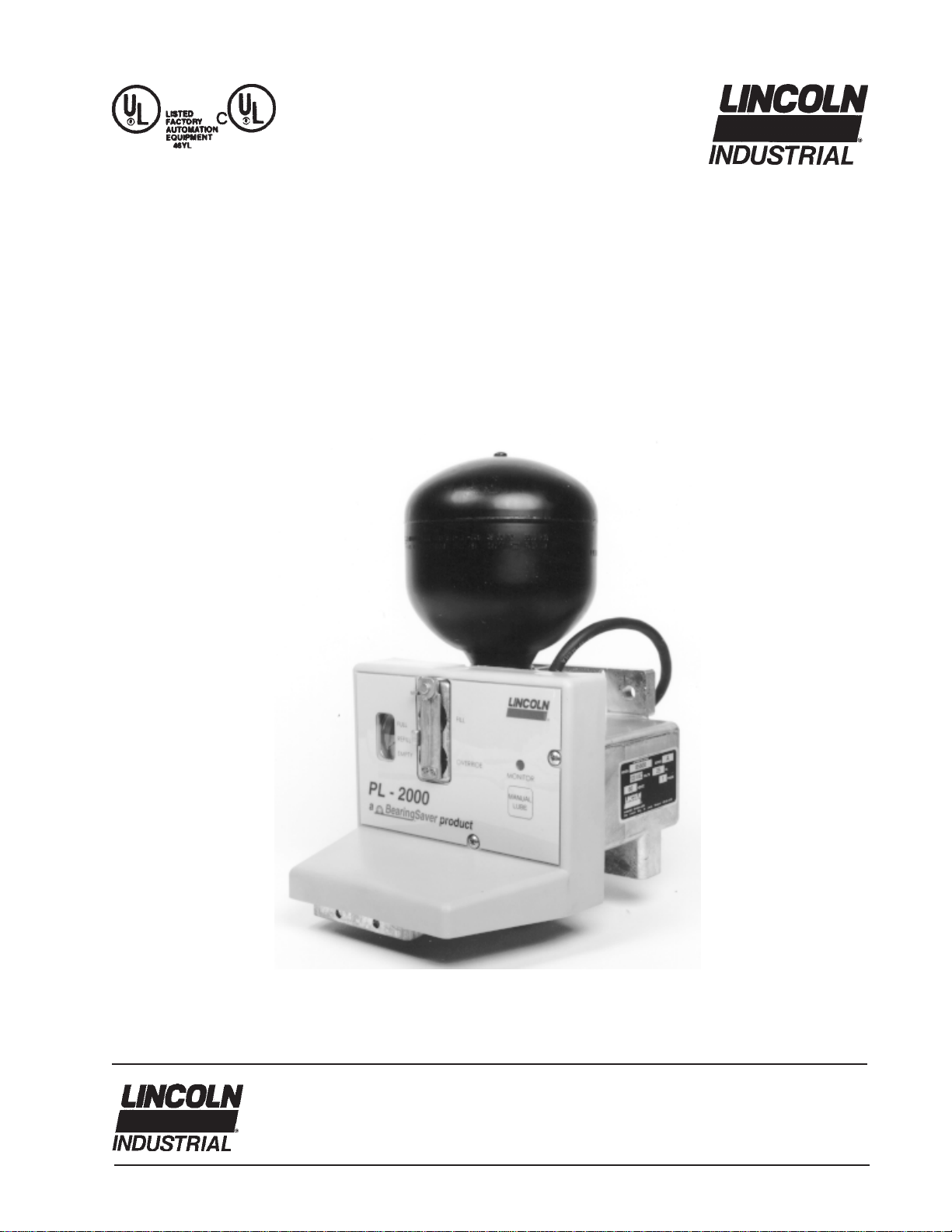
Description
The Lincoln PL-2000 is a programmable lubrication
system that can supply grease to a maximum of 18
fittings. It can dispense NLGI #2 grease at timed
intervals from 2 hours to 30 days. Each cycle of the
system dispenses .012 in³. of grease per outlet.
The lubricant reservoir is divided by a special dia-
phragm, with the upper portion of the reservoir
precharged for life with nitrogen gas. Filling the
reservoir with grease provides the pressure neces-
sary to dispense lubricant to the fittings.
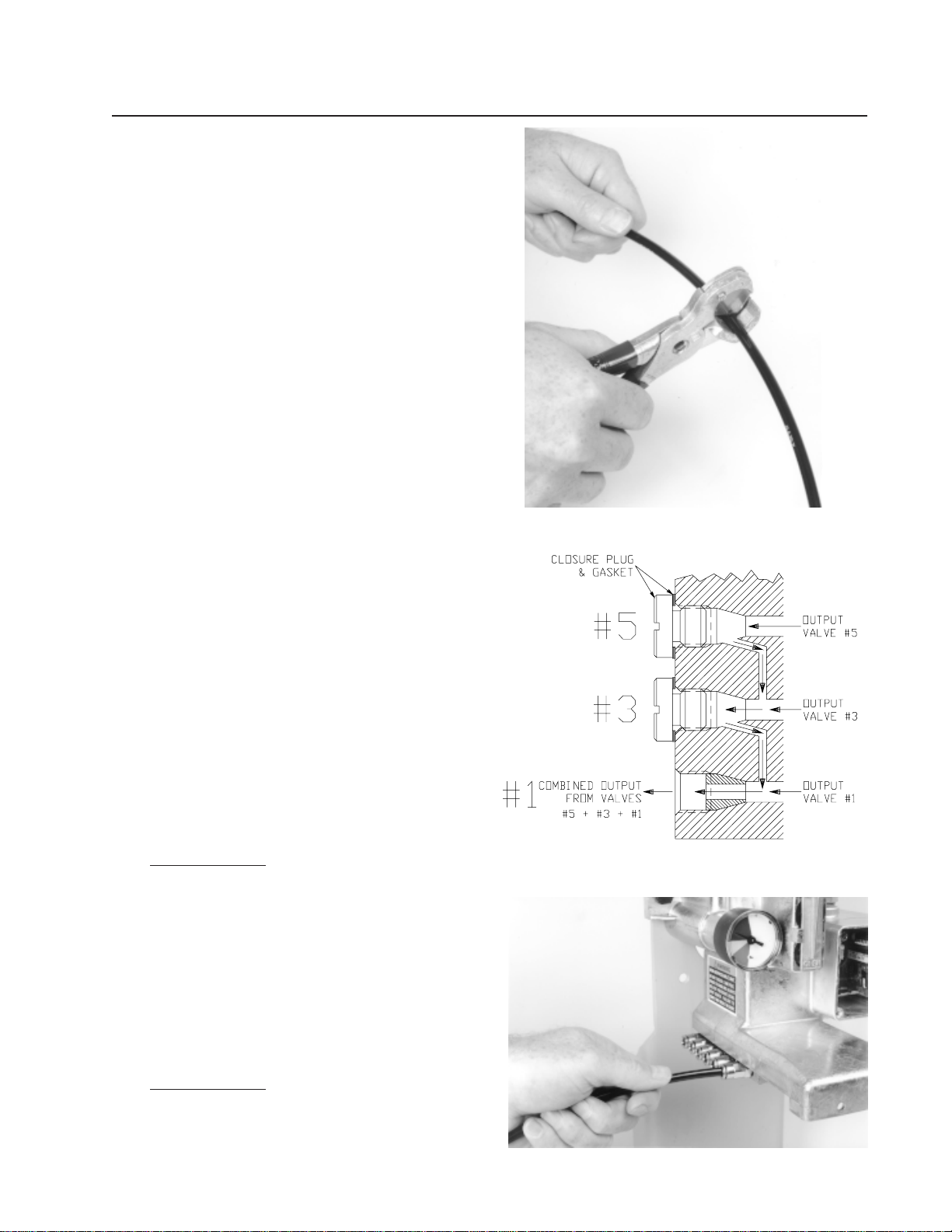
A signal from the system timer opens a solenoid
valve and allows lubricant from the reservoir to flow to
a divider valve. When all grease fittings have re-
ceived lubricant, an internal cycle switch turns the
system off, completing one lubrication cycle.
The lube timer has a memory. If power is turned off
for less than 72 hours, it “remembers” where it
stopped, and will restart at the same point when
power is restored. (This prevents over-lubrication of
the machine if power is switched on and off over short
periods of time.) If power is off for more than 72
hours, the timer will begin a lube cycle when power
turns on, then start timing toward the previously
selected lubrication interval.
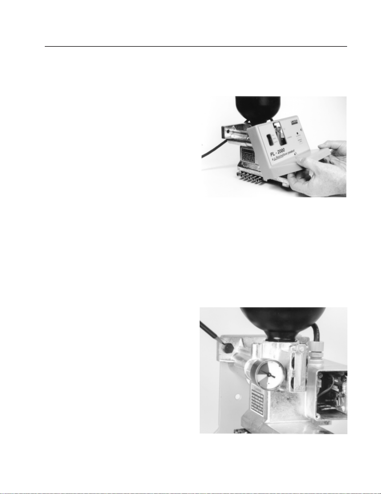
Installation Instructions
Use the following recommendations to select a
mounting location for the PL-2000 lubricator.
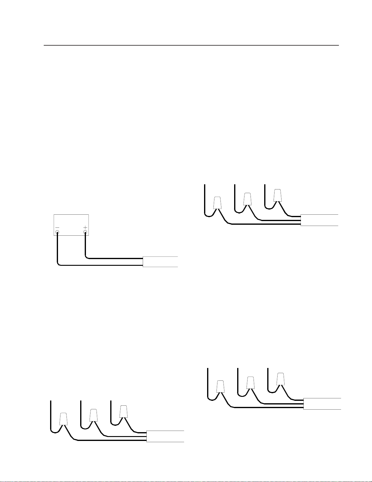
• Keep the feed lines as short as possible.
• Provide access to fill, clean, and monitor the
PL-2000.
• Allow adequate room for mounting and connecting
feed lines to the PL-2000.
• Installing the PL-2000 with the reservoir on top is
preferred, but it may be installed in any orientation
without affecting its operation.