Page Number - 7
Form 403046
Hydraulic Spray Lubrication System®
Model 85418
reassembly. Seals should be properly lubricated at
assembly. The measuring valve may be reassembled in the
reverse order of disassembly. The heating element (35)
should be evenly coated with Chromalox heat transfer and
release coating #014293 or equivalent before inserting into
valve body. Old heat release compound can be removed
with a water dampened rag. All pipe threads should have
Loctite 242 or equivalent applied at assembly. Proceed to
Hydraulic Charging Procedure below.
Hydraulic Charging Procedure
A suitable hand operated pump, capable of developing 2000
PSI, with a pressure gage to monitor charging pressure is
required for properly charging the hydraulic circuit of the
measuring valve assembly. The Hydraulic Spray System will
not operate properly unless properly charged prior to being
placed in service.
1. Connect hand pump outlet with pressure gage to inlet
(1/8 NPT) of check valve (32).
2. Hand pump reservoir must be filled with Dexron II
automatic transmission fluid.
3. Be sure that the hydraulic dump valve (33) is open on the
measuring valve body.
4. Operate the hand pump until oil, free of air, flows from the
dump valve port on the side of the measuring valve body
(53).
5. Close the dump valve by turning the setscrew (33) with a
3/16 Allen wrench clockwise and tighten by hand.
6. Continue to operate the hand pump, slowly, until a steady
pressure of 2000 PSI is reached on the pressure gage.
7. Check for leaks around the hydraulic dump valve port.
8. Disconnect the hand pump from the check valve (33) and
plug the check valve inlet with pipe plug (31). The pipe
plug should have loctite 242 or equivalent applied to the
threads prior to insertion.
9. Install the measuring valve assembly into the enclosure
in the reverse order of disassembly.
The accumulator is charged
with Nitrogen gas to 1,500 PSI.
Any attempt to discharge without
proper equipment can be
hazardous. Do not remove
protective plastic cap.
Do not attempt to open service
valve on top of accumulator.
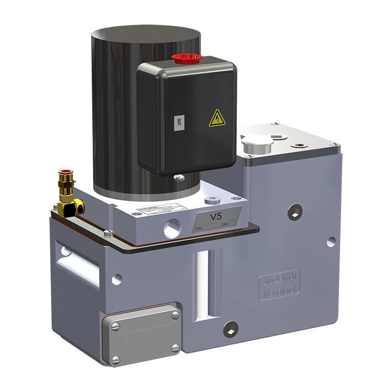
Measuring Valve Disassembly and Repair
Do not attempt any disassembly until you are sure that all
pressure has been dissipated from the hydraulic circuit.
1. Disconnect and lockout power to the Hydraulic Spray
System.
2. Discharge the Hydraulic Spray System per Discharge
Procedures 1 & 2.
3. Remove the measuring valve assembly per the removal
procedure above.
4. Remove set screw (33) and ball (34) from valve body.
5. Remove pipe plug (31) and check valve (32).
6. Remove accumulator (50) and adapter (52) from valve body.
7. Remove thermostat (49) by removing two screws(56).
8. Remove solenoid coil (46) by removing nut from stem of
solenoid valve.
9. Remove pressure switch (48) by turning counterclockwise
from valve body.
10. Loosen 6-32 set screw (36) and remove heating
element from valve body. (A hole is provided to aid in the
removal of the heating element, in the valve body
opposite the heater.)
11. All electrical components may be set aside.
12. Remove set screw (22) and locknut (23) from adjustment
housing (24).
13. Remove adjustment housing (24) from valve body (53).
14. Remove adjustment plunger (28) from adjustment
housing (24).
15. Remove the piston (30) from the valve body (53). Blowing
air from a blow gun into adapter (41) may assist piston
removal.
16. Remove adapters (42) and (41).
17. Remove check valve (39).
18. Remove solenoid valve (44).
Clean all components, except for electrical components, in
a suitable solvent. Check all components for damage or
wear. The accumulator (50) has no serviceable
components in side of it and no further disassembly should
be attempted. Replacement accumulators are supplied
pre-charged with nitrogen gas by Lincoln Industrial. Lincoln
Industrial recommends that all seals be replaced prior to
