Linergy EI58SA/E User manual
EUROINVERTER
CARATTERISTICHE GENERALI:
- Led spia presenza rete e ricarica della batteria.
- Funzionamento con batterie al Ni-Cd.
- Dispositivo di protezione contro la scarica eccessiva della batteria.
- Prodotto conforme alle normative europee EN 61347 e idoneo ad essere montato in apparecchi
conformi alla norma EN 60598-2-22.
- Prodotto conforme alla direttiva europea 2002/95/CE RoHS
- Apparecchio adatto per montaggio su superfici normalmente infiammabili.
- Corpo in materiale plastico conforme alle normative vigenti.
CONNESSIONE E FISSAGGIO DELL'APPARECCHIO: L'alimentatore è previsto unicamente per essere
alimentato da batterie non associate a circuiti di ricarica a funzionamento continuo o intermittente. La
scatola dell Euroinverter è stata disegnata in modo da impedire l'inversione della polarità della batteria,
effettuare la connessione come mostrato in fig.10.
CABLAGGIO DEL TUBO FLUORESCENTE: Nella connessione del tubo fluorescente con il Fastinverter
si raccomanda di usare cavi il più corti possibile e ben distesi come mostrato in fig.13.
È possibile attaccare l’ Euroinverter al soffitto con delle viti oppure si può usare il biadesivo in dotazione.
Tagliare le due striscie in quattro pezzi come mostrato in fig.14.
La protezione contro i contatti accidentali non dipende dall'involucro dell'apparecchio di illuminazione.
GB
GENERAL CHARACTERISTICS:
- Indicator led for the presence of power supply and charge of battery.
- Operation with Ni-Cd.
- Electronic protection device for excessive discharge of the battery.
- Device conform to rules EN 61347 and suitable to be mounted in devices that conform the rules EN
60598-2-22
- Device designed in accordance with the rules 2002/95/CE RoHS
- Device suitable for mounting on normally inflammable surfaces.
- Plastic body in accordance with the rules in force.
CONNECTION AND FIXING OF THE DEVICE:
The plastic case of the Euroinverter
is designed to avoid the polarity inversion of the battery, connect the battery as shown in fig.10. You can
attack the Euroinverter to the ceiling with screws or you can use the double adhesive tape in endowmen.
Cut the two stripes in four pieces as shown in fig.14.
CONNECTION OF THE FLUORESCENT TUBE: In the connection of the fluorescent tube to the Fastinverter
the wires must be short and straight
as shown in fig.13.
The protection against the accidental contacts do not depend on the case of the illumination device.
The device is provided only to be supplied with batteries not
associated to recharge circuits with intermittent or continuous operation.
ELECTRONIC BALLAST FOR EMERGENCY
I
ALIMENTATORE ELETTRONICO DI EMERGENZA
CARATTERISTICHE TECNICHE
TECHNICAL CHARACTERISTICS
ALIMENTAZIONE/ POWER SUPPLY
POTENZA ASSORBITA/ POWER ABSORPTION
2
SPESSORE DEL FILO PER COLLEGAM. / WIRE DIAMETER (mm )
TENSIONE A CIRCUITO APERTO/ VOLTAGE ON OPEN LOAD
GRADO DI PROTEZIONE/ PROTECTION DEGREE
CLASSE DI ISOLAMENTO/ INSULATION CLASS
TEMPERATURA DI FUNZIONAMENTO/ OPERATING TEMPERATURE
230Vac - 50Hz
2VA
IP20
II
0÷40°C
0,75÷1
1600V/50kHz
Il cassonetto barrato sull’apparecchio specifica che il prodotto deve essere consegnato ai centri di raccolta
autorizzati per un corretto smaltimento. Rivolgersi all’ufficio competente del proprio ente locale per
informazioni sulla raccolta e sui termini di legge.
The crossed out waste bin symbol indicates that the product should be taken to an authorized waste
collection centre which can dispose of it properly. For information on waste collection centres and on current
waste disposal legislation, please contact your local waste disposal authority.
CONDIZIONI DI GARANZIA / WARRANTY CONDITION
La garanzia sugli apparecchi di emergenza è di 2 anni dalla data di vendita. La garanzia decade se il
prodotto è stato manomesso o riparato da personale non autorizzato LINERGY.
The warranty on the emergency luminaire is 2 years from the sales date. The warranty voids if the product
has been mishandled or repaired by personnel not authorized by LINERGY.
FF
MODELLO LAMPADA
AUTONOMIA
BATTERIA RESA
TEMPO DI
CARICA FREQUENZA
CON LAMPADA SENZA LAMPADA
WITH LAMP WITHOUT LAMP
FREQUENCY
CORRENTE
NOMINALE
NOMINAL
CURRENT
PESO
(Con Batt)
MODEL LAMP
DURATION
BATTERY
FLUX
FACTOR
RECHARGE
TIME
WEIGHT
(with Batt)
EI58SA/E
18W G13 FD
36W G13 FD
58W G13 FD
1h30’
1h
1h
NiCd 6V 1,3Ah
NiCd 6V 1,3Ah
NiCd 6V 1,3Ah
15%
10%
7% 35kHz
35kHz
35kHz
50kHz
50kHz
50kHz
1000mA
900mA
700mA24 h
24 h
24 h
0,4 kg
0,4 kg
0,4 kg
BATTERY
Fig.14: fissaggio
con biadesivo
fixing with the double
adhesive tape
BATTERIA
BATTERY
tubo fluorescente
fluorescent lamp
euroinverter
Fig.15: per aprire fare leva con
un giravite nel punto indicato
to open use a screwdriver
in the point indicated
Fig.16: rispettare la
polarità della batteria
be careful to the
polarity of the battery
fig.13: cavi corti e ben distesi
wires short and straight
IP20
230 Vac - 50 Hz
Batt.
2
3
1
4
230V~
RETE/POWER
NERO/BLACK
ROSSO/RED
BATT
EUROINVERTER
B
A
fig.1
L
A
M
P
6
7
5
8
10
11
9
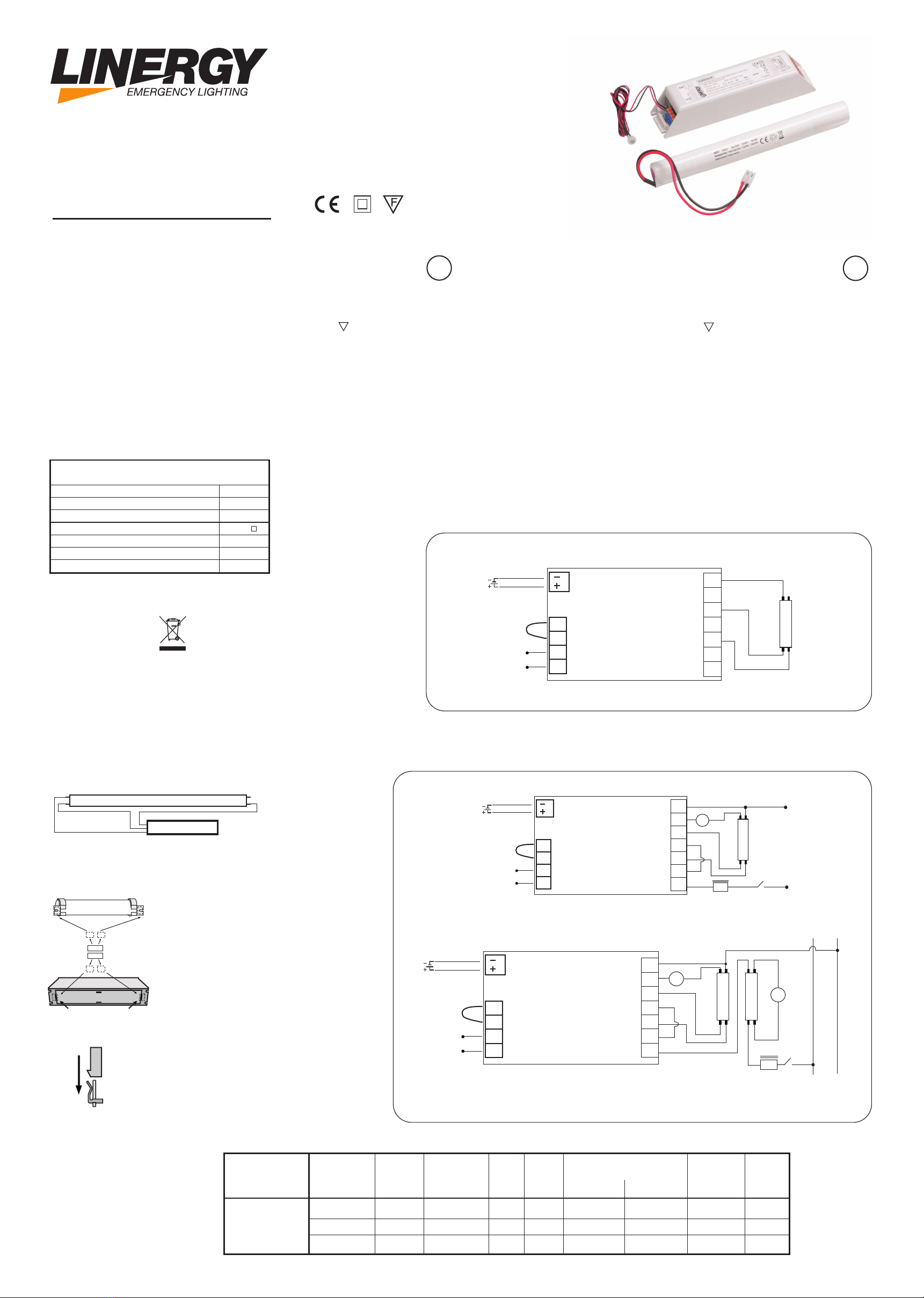
SCHEMA CON REATTORE ELETTROMAGNETICO
SCHEME WITH ELECTROMAGNETIC BALLAST
SCHEMA PER COLLEGAMENTO SOLO EMERGENZA
SCHEME FOR NOT MAINTAINED CONNECTION
Batt.
2
3
1
4
230V~
RETE/POWER
NERO/BLACK
ROSSO/RED
BATT
EUROINVERTER
B
A
L
A
M
P
L
N
s
Fig.2: sempre accesa con reattore e starter
mantained with ballast and starter
6
6
7
7
5
5
8
8
10
10
11
11
9
9
Batt.
2
3
1
4
230V~
RETE/POWER
NERO/BLACK
ROSSO/RED
BATT
EUROINVERTER
B
A
L
A
M
P
1*
s
s
Fig.3: sempre accesa con reattore, starter e due tubi in serie
mantained with ballast, starter and two tubes in series
LN
L
A
M
P
2
reattore/ballast
reattore/ballast
*solo la lampada 1 si accende in emergenza
only lamp 1 turns on during the emergency

fig.4: Schema originale del reattore
Original Scheme of the ballast
fig.8: Schema originale del reattore
Original Scheme of the ballast fig.10: Schema originale del reattore
Original Scheme of the ballast
fig.5: Schema di collegamento tra reattore ed Euroinverter
Wiring scheme between Ballast and Euroinverter
fig.9: Schema di collegamento tra reattore ed Euroinverter
Wiring scheme between Ballast and Euroinverter fig.11: Schema di collegamento tra reattore ed Euroinverter
Wiring scheme between Ballast and Euroinverter
fig.7: Schema di collegamento tra reattore ed Euroinverter
Wiring scheme between Ballast and Euroinverter
LINERGY SRL - via A. De Gasperi 9 - Acquaviva Picena (AP) - ITALY - tel.0735.5974 - fax 0735.597474 - www.linergy.it - info@linergy.it - ISTEUROINV/E - Ver.3.2
Batt.
2
3
1
4
230V~
RETE/POWER
NERO/BLACK
ROSSO/RED
BATT
EUROINVERTER
EI58SA/E
B
A
L
A
M
P
L AMP 1
L AMP 1
L AMP 2
L AMP 2
LN
1
2
REATTORE ELETTRONICO
ELECTRONIC BALLAST
3
4
L
N
Osram QTP 1X58
230V~
1
1
55
2
2
6 6
REATTORE ELETTRONICO
ELECTRONIC BALLAST REATTORE ELETTRONICO
ELECTRONIC BALLAST
3
3
7 7
4
4
8
L
L
N
N
L
A
M
P
1
2
REATTORE ELETTRONICO
ELECTRONIC BALLAST
3
4
L
N
Osram QTP 1X58
6
7
5
8
10
11
9
SCHEMI CON REATTORE ELETTRONICO
SCHEMES WITH ELECTRONIC BALLAST
*Questo schema è un esempio valido solo con Reattore Osram QTP 1x58W.
*This scheme is an example valid only for Osram QTP 1x58W ballast.
A
B
CD
EF
GH
REATTORE ELETTRONICO
ELECTRONIC BALLAST
Batt.
2
3
1
4
230V~
RETE/POWER
NERO/BLACK
ROSSO/RED
BATT
EUROINVERTER
EI58SA/E
B
A
L
A
M
P
1
L
A
M
P
2
LN
L
N
230V~
6
7
5
8
10
11
9
LAMP1
IN EMERGENZA
*Questo schema è un esempio valido solo con Reattore Helvar 2x58 NGN
*This scheme is an example valid only for Helvar 2x58 NGN ballast.
fig.6: Schema originale del reattore
Original Scheme of the ballast
REATTORE ELETTRONICO
ELECTRONIC BALLAST
A B
CD
EF
H G
Batt. Batt.
22
33
11
44
230V~230V~
RETE/POWER RETE/POWER
NERO/BLACK NERO/BLACK
ROSSO/RED ROSSO/RED
BATT BATT
EUROINVERTER
EI58SA/E
EUROINVERTER
EI58SA/E
REATTORE
ELETTRONICO
ELECTRONIC
BALLAST
REATTORE
ELETTRONICO
ELECTRONIC
BALLAST
LAMP 2
LAMP 2
BB
AA
L
A
M
P
1
L
A
M
P
1
LL
NN
230V~230V~
66
77
55
88
10 10
11 11
99
LAMP1 IN EMERGENZA LAMP1 IN EMERGENZA
22
NN
33
11
LL
44
7 7
8
55
66
*Per ulteriori schemi di collegamento certificati
con reattori Osram, Philips, Vossloh, Helvar, ERC,
TCI, Tridonic etc, inviare una richiesta:
*For any further certified wiring diagrams
with ballast Osram, Philips, Vossloh, Helvar, ERC,
TCI, Tridonic etc. send a request:
+39 0735-597474
support@linergy.it support@linergy.it
0735-597474
Other Linergy Lighting Equipment manuals

Linergy
Linergy LEDY Instruction Manual

Linergy
Linergy VA03N20EBRD User manual

Linergy
Linergy STEP Operating and maintenance manual

Linergy
Linergy SU30N10AGR Product manual

Linergy
Linergy VIALED IP65 User manual

Linergy
Linergy VIALED NET User manual

Linergy
Linergy PRODIGY PR08F10EBRT User manual

Linergy
Linergy SELFIE User manual

Linergy
Linergy LYRA EVO Product manual

Linergy
Linergy PRODIGY PR08F10EBR Operating and maintenance manual


