11/81
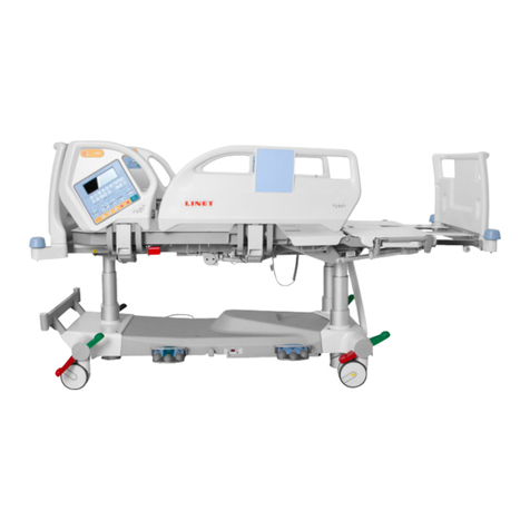
3.2.2.2 STOP button located on the LCD panel
The main STOP button immediately stops all movements of the bed (undesirable movement) and deactivates GO if
positioning is not permitted or during failure of electrical components. A 10 kΩresistor is connected in parallel to the
STOP button inside the keypad. The electronics of the system detect the correct connection of the resistor
(connection of keypad and functionality of the STOP button). Its interruption (error in keypad, faulty resistor, cable...)
is signalled by an intermittent tone from the control unit. Without correct connection of both controllers to the
resistors (both iBoards), this function after activation with the GO button is only active for 5s. If at least one resistor
(iBoard) is connected, GO is active as standard for 3 minutes.
3.2.2.3 GO button located on the ACP panels, the handset, and side rails
All the control functions are conditional on the GO button being pressed (only the CPR and STOP button do not
require the GO button to be pressed). When GO is pressed, the control system is activated for 3 minutes (except
during fault of the STOP circuit –described above). When any function is pressed for more than 2 seconds, the
button is released for an extension of the GO period by another 3 minutes. When a function is pressed for less than
2 seconds, the original 3 minutes remains. After 3 minutes from the previously selected function, the control
electronics are deactivated and any further function is conditional on the GO button being pressed again. Pressing
the GO button is only valid if no other control button has been pressed at the same time. The use of the GO button
significantly limits the possibility of accidental movement of the bed during a fault or from unintentional pressing of
controllers.
3.2.2.4 Simultaneous pressing of any two buttons
In the event of uncontrollable movement of the bed caused by, for example, a broken button, the bed may be
stopped immediately using the STOP button or by pressing any key (it must be a button other than the button
causing the fault, however). If it is pressed for more than 1 second, the movement of the bed will be blocked and a
STOP code announced on the iBoard display (see table of STOP codes). Unblocking is automatic after all presses
have been released (including the error ones).
3.2.2.5 Double power switches
The power switches are doubled. The main switch is a relay type and controlled with a microprocessor. Switching it
on is conditional to the priority in hardware detection of commands from external controllers independent of the
microprocessor. This means that switching it on is dependent on of the functional buttons being pressed, which is
detected by a separate circuit independent of the microprocessor. This ensures safety even in a situation where the
microprocessor would activate a positioning function spontaneously as a result of an error. Switching it on is also
conditional on a fault-free connection of the STOP button and internal error diagnostics. The switching and
commutation of the electrical motor lifting units is safeguarded by relays. The second switch is a semi-conductor
type. It provides safety and speed control, as well as delayed switching and early interruption of current before the
relay contacts to protect their contacts and extend their life. The fault-free functioning of both switching elements is
monitored independently. A fault in these elements resulting in the electronics no longer being resistant to the first
error is signalled by a regular flashing of the mains LED. At this moment, only one movement of the bed is permitted,
after which this mode is signalled by a regular flashing of the mains and all locks LED. Further movement is possible
only after pressing the STOP button. After 5 individual movements the control unit is blocked permanently.
3.2.2.6 RC circuits –protection against shorting and spontaneous movement
An RC circuit is installed in all the analogue control elements connected to the ACP control unit (ACP, handset,
mobilift, foot controller). The value of the RC circuit resistor is 390 Ω. If the function is not active, the circuit
resistance is infinite as standard. When any function is pressed, the resistance of the circuit is 390 Ω, the function is
detected as valid and it begins. If a short is present in the circuit of the button, the resistance drops below 200 Ω, the
control unit detects the function as invalid and positioning does not occur. The RC circuit serves to prevent
spontaneous movements of the bed caused by a short in the wiring.


