Doc: MHIT101A1012.doc 01/08/2013 p. 3 / 38
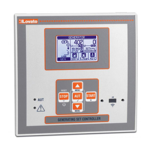
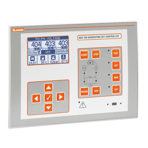
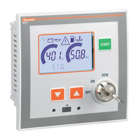
Funzioni dei tasti frontali
Tasto STOP/RESET - Esegue un arresto manuale del motore ed esce
dalla modalità Automatico (led verde AUT si spegne). Da utilizzare per
resettare gli allarmi.
Tasto AUT - Serve per la scelta della modalità di funzionamento in
automatico. Il LED verde AUT si accende.
Tasto START – Esegue un avviamento manuale del motore, ed esce dalla
modalità automatico passando in manuale. Tenendolo premuto si può
prolungare manualmente la durata dell’avviamento. Premendo
contemporaneamente START e si può commutare manualmente il
contattore di rete. Premendo contemporaneamente START esi può
commutare manualmente il contattore di generatore.
Tasti e- Servono per scorrere le pagine del display o per
selezionare la lista di opzioni di un menu. Premendo contemporaneamente
+si richiama il menu principale con le icone rotanti.
Front buttons functions
STOP / RESET button - Performs a manual shutdown of the engine and
then exit the Automatic (AUT green LED turns off). Use to reset the
alarms.
AUT button - Used to select the operation mode automatically. The
green AUT LED lights.
START button - Performs a manual start of the engine, and exits from
the automatic mode, moving to manual mode. Holding it down you can
manually extend the duration of cranking. Pressing simultaneously
START and you can manually switch the mains contactor. Pressing
simultaneously START and you can manually switch the generator
contactor.
and buttons - Used to scroll through the display pages or to select
the list of options in a menu. Simultaneously pressing + calls up
the main menu with rotating icons.
LED frontali
LED modalità AUT (verde) – indica la modalità automatica attiva.
LED di allarme (rosso) – Lampeggiante, indica che un allarme è attivo.
Front LED indications
AUT LED (green) – Indicates that the automatic mode is active.
Alarm LED (red) – Flashing, indicates an active alarm.
Modi operativi
Per cambiare modo operativo è necessario premere per almeno 0,5 sec il
tasto corrispondente al modo operativo desiderato.
Modo STOP/RESET (Stop manuale) - Il motore non viene mai avviato.
Passando a questo modo di funzionamento, se il motore è in moto viene
arrestato immediatamente. Il relè contattore rete viene chiuso. Questa
modalità riproduce lo stato dell’RGK600 quando esso non è alimentato. Per
poter accedere alla programmazione dei parametri ed al menu comandi è
necessario predisporre il sistema in questa modalità. In modo STOP, la
sirena non viene mai attivata.
Modo START (Start manuale) - Il motore viene avviato manualmente (si
esce dal modo AUT). E’ possibile la commutazione manuale del carico con
le modalità descritte nel precedente capitolo Funzioni dei tasti frontali.
Modo AUT (Automatico) - La modalità AUT è evidenziata dalla
accensione del corrispondente LED verde. Per RGK600, il motore viene
avviato automaticamente in caso di assenza rete (fuori dai limiti impostati)
e fermato al rientro della stessa, secondo tempi e soglie impostati nel menu
M13 Controllo rete. Con presenza tensione, la commutazione del carico
avviene automaticamente nelle due direzioni.
Per RGK600SA, l’avviamento e l’arresto vengono comandati da remoto
tramite un ingresso digitale (avviamento remoto) normalmente comandato
da un ATS. La commutazione del carico può essere automatica o
comandata da remoto.
Per entrambi i modelli, in caso di mancato avviamento del motore vengono
ripetuti i tentativi fino al numero massimo programmato. Il test automatico,
se abilitato, viene eseguito alle scadenze prefissate.
Operating modes
To change the operating mode press for at least 0.5 sec the button
correspondent to the desired mode.
STOP/RESET mode (Manual stop) - The engine will not start. The
engine will stop immediately when this mode is selected- The mains
contactor is closed. This mode reproduces the state of the RGK600
when it is not powered. Use this mode to program the parameters and
use the commands menu. The siren is disabled in STOP mode.
START Mode (Manual start) - The engine is started manually (exiting
AUT mode). It is possible to manually switch the load as explained in the
Front button function chapter.
AUT Mode (Atomatic) – The AUT mode is highlighted by the relative
green LED. The engine of the RGK600 is started automatically in the
case of a mains outage (outside the set limits) and stops when the mains
parameters are once again within said limits, on the basis of the times set
in menu M13 Mains control. In the presence of voltage, the load is
switched automatically in both directions.
The RGK600SA is started and stopped remotely through a digital input
(remote starting) normally controlled by an ATS. The load can be
switched automatically or controlled remotely.
For both models, if the engine fails to start, the system continues
attempting to start the engine up to the maximum number of programmed
attempts. If the automatic test is enabled, it runs at the preset times.
Messa in tensione
xRGK600 e RGK601 (versioni AMF) vengono alimentati direttamente
collegando tensione ai morsetti di batteria.
xRGK600SA e RGK601SA (versioni stand-alone) hanno invece un
circuito di accensione e spegnimento elettronico. Con alimentazione
collegata, per accendere l’apparecchio premere il tasto STOP per 1s .
Per spegnere l’apparecchio tener premuto il tasto STOP per 5s.
xAlla accensione l’apparecchio si pone normalmente in modo STOP.
xSe si necessita che mantenga lo stesso modo di funzionamento
precedente lo spegnimento, si deve modificare il parametro P01.03 nel
menu M01 Utilita’.
xL’apparecchio può essere alimentato indifferentemente sia a 12 che a
24VDC, ma necessita della corretta impostazione della tensione di
batteria nel menù M05 Batteria, diversamente si avrà un’ allarme relativo
alla tensione di batteria.
xÈ normalmente indispensabile impostare i parametri del menù M02
Generale (tipo di connessione, tensione nominale, frequenza di sistema)
e dei menù M11 Avviamento Motore e i menu relativi al tipo di motore
utilizzato (sensori, CAN ecc.).
Power-up
xRGK600 and RGK601 (AMF versions) are switched on directly by
applying power to battery terminals.
xRGK600SA and RGK601SA (stand-alone versions) instead have an
electronic switch-on/off circuit. With power applied, to switch on the
unit press and hold STOP button for 1 sec. To switch off the unit press
and hold STOP button for 5s.
xThe system normally powers up in STOP mode.
xIf you want the operating mode used before the system powers down
to be maintained, change parameter P01.03 in menu M01 Utility.
xThe system can be powered at both 12 and 24 VDC, but the correct
battery voltage must be set in menu M05 Battery, or a battery voltage
alarm will be generated.
xThe parameters of menu M02 General (type of connection, rated
voltage, system frequency), menu M11 Engine Starting, and the
menus for the type of engine used (sensors, CAN, etc.) should
normally be set.

