I333 I GB 08 13 31100160
9
RISORSE AGGIUNTIVE
– I moduli di espansione forniscono delle
risorse aggiuntive che possono essere
sfruttate tramite gli opportuni menu di
impostazione.
– I menu di impostazione che riguardano le
espansioni sono disponibili anche se i moduli
non sono fisicamente presenti.
– Dato che è possibile aggiungere più moduli
della stessa tipologia (ad esempio due
interfacce di comunicazione) i relativi menu di
impostazione sono multipli, identificati da un
numero progressivo.
– Di seguito una tabella che indica quanti
moduli di ogni tipo possono essere montati
contemporaneamente. Il numero totale di
moduli deve essere < 3.
ADDITIONAL RESOURCES
– The expansion modules provide additional
resources that can be used through the
dedicated setup menus.
– The setup menus related to the expansions
are always accessible, even if the expansion
modules are not physically fitted.
– Since it is possible to add more than one
module of the same type (for instance two
communication interfaces), the setup menus
are multiple, identified by a sequential
number.
– The following table indicates how many
modules of each group can be mounted at the
same time. The total number of modules must
be less or equal than 3.
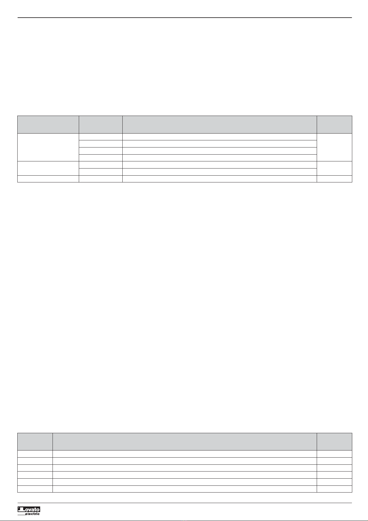
TIPO MODULO CODICE FUNZIONE Nr. MAX
MODULE TYPE CODE FUNCTION MAX No.
COMUNICAZIONE EXM 10 10 USB 1
COMMUNICATION EXM 10 11 RS-232
EXM 10 12 RS-485
EXM 10 13 ETHERNET
I/O DIGITALI / DIGITAL I/O EXM 10 00 2 IN + 2 SSR / 2 IN + 2 SSR 3
EXM 10 01 2 IN + 2 RELE’ / 2 IN + 2 RELAYS
MISTI / MIXED EXM 10 20 485 + 2 RELE’ / 485 + 2 RELAYS 2
INGRESSI, USCITE, VARIABILI INTERNE,
CONTATORI
– Gli ingressi e le uscite digitali forniti dai
moduli di espansione sono identificati da una
sigla e da un numero progressivo. Ad
esempio gli ingressi digitali sono denominati
INPx, dove x rappresenta il numero
dell’ingresso. Allo stesso modo, le uscite
digitali sono denominate OUTx.
– Bisogna considerare che il DMED310
incorpora nella unità base un ingresso digitale
in VAC (denominato INP1) e due uscite
statiche (OUT1 e OUT2). L’ingresso INP2 è
riservato per future applicazioni.
– La numerazione degli I/O dei moduli di
espansione, se installati, prosegue la
numerazione degli I/O integrati, con una
numerazione progressiva da sinistra a destra.
Ad esempio montando un modulo con 2
ingressi e 2 uscite aggiuntive, questi saranno
denominati INP3-INP4 e OUT3-OUT4.
– Per ciascun I/O esiste un menu di
impostazione che consente di specificarne la
funzione e le proprietà.
– Allo stesso modo degli ingressi/uscite,
esistono delle variabili interne (bit) che
possono essere associate alle uscite o
combinate fra loro. Ad esempio si possono
applicare delle soglie limite alle misure
effettuate dal multimetro (tensione, corrente
etc.). In questo caso la variabile interna,
denominata LIMx, sarà attivata quando la
misura risulta essere fuori dai limiti definiti
dall’utente tramite il relativo menu di
impostazione.
– Infine è possibile gestire fino a 4 contatori
(CNT1…CNT4) che possono conteggiare
impulsi provenienti dall’esterno (quindi da
ingressi INPx) oppure il numero di volte per
cui si è verificata una determinata condizione.
Ad esempio definendo una soglia LIMx come
sorgente di conteggio, sarà possibile contare
quante volte una misura ha superato un certo
valore.
– Di seguito una tabella che raccoglie tutti gli
I/O e le variabili interne gestiti dal DMED310.
INPUTS, OUTPUTS, INTERNAL VARIABLES,
COUNTERS
– The inputs and outputs of the expansion
modules are identified by a code and a
sequence number. For instance, the digital
inputs are identified by code INPx, where x is
the number of the input. In the same way,
digital outputs are identified by code OUTx.
– The DMED310 incorporates, in the base unit,
one digital input in VAC (named INP1) and
two static outputs (OUT1 and OUT2). The
INP2 input is reserved for future applications,
it is not available and cannot be used.
– The numbering of I/O expansion modules, if
installed, continues the numbering of built-in
I/O, with a progression from left to right. For
example, installing an expansion module with
two inputs and two outputs, these will be
named INP3-INP4 and OUT3-OUT4.
– For every I/O, there is a dedicated setting
menu that allows to specify functionality and
properties.
– In a similar way, there are some internal bit-
variables (markers) that can be associated to
the outputs or combined between them. For
instance, it is possible to apply some limit
thresholds to the measurements done by the
multimeter (voltage, current, power, etc.). In
this case, an internal variable named LIMx will
be activated when the measurements go out
of the limits defined by the user through the
dedicated setting menu.
– Finally, it is possible to manage up to 4
counters (CNT1..CNT4) that can count pulses
coming from an external source (through a
digital input INPx) or the number of times that
a certain condition has taken place. For
instance, defining a limit threshold LIMx as
the count source, it will be possible to count
how many times one measurement has
exceeded a certain limit.
– The following table groups all the I/O and the
internal variables managed by the DMED310.
COD DESCRIZIONE Nr. MAX (x)
CODE DESCRIPTION RANGE (x)
INPx Ingressi digitali / Digital inputs 1…16
OUTx Uscite digitali / Digital outputs 1…8
LIMx Soglie limite / Limit thresholds 1…8
REMx Variabili da remoto / Remote-controlled variables 1…8
PULx Impulsi / Energy count pulses 1…5
CNTx Contatori / Counters 1…4