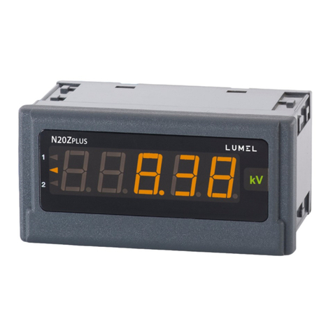
Lumel N31U User manual

N31U Service manual 1
DIGITAL PANEL METER
SERVICE MANUAL

N31U Service manual 2
Contents
1 Application......................................................................................................................................3
2 Meter set..........................................................................................................................................4
3 Basic requirements, operational safety............................................................................................5
4 Installation.......................................................................................................................................5
4.1 Installation method..................................................................................................................5
4.2 E ternal connection diagram...................................................................................................6
4.3 E amples of connecting the e ternal transducers....................................................................9
5 Service.............................................................................................................................................9
5.1 Description of the frontal plate................................................................................................9
5.2 Buttons' functions...................................................................................................................11
5.3 Programming meter parameters.............................................................................................12
5.3.1 How to change quantity of a selected parameter...........................................................14
5.3.2 Programmable meter parameters, default parameters....................................................15
5.4 Meter functions......................................................................................................................19
5.4.1 Measurement..................................................................................................................19
5.4.1.1 Averaging the measuring quantity..........................................................................20
5.4.1.2 Minimum and ma imum measuring values...........................................................20
5.4.1.3 Mathematical functions..........................................................................................21
5.4.1.4 Individual characteristic.........................................................................................21
5.4.2 Alarm output..................................................................................................................23
5.5 RS-485 interface....................................................................................................................24
5.5.1 Connection.....................................................................................................................24
5.5.2 Description of the MODBUS protocol implementation................................................25
5.5.3 Implemented functions of MODBUS protocol..............................................................25
5.5.4 Map of the registers........................................................................................................26
5.5.4.1 Registers 4000 – 4024............................................................................................26
5.5.4.2 Registers 4200 – 4219............................................................................................29
5.5.4.3 Registers 7500 – 7530 and 7000 – 7030................................................................30
5.5.4.4 Registers 7600 – 7668 and 7200 – 7336................................................................31
6 Error codes.....................................................................................................................................33
7 Technical data................................................................................................................................34
8 Ordering code................................................................................................................................36

N31U Service manual 3
1 Application
The N31U meter is a digital panel meter adapted to be fixed to the panel designed to
measure standard analog signals used in automation. N31U meters enable the
measurement of standardized voltage and current signals, the signals from RTD and
thermocouple sensors. The measuring value can be freel converted into the required
value using the mathematical functions or an individual characteristic.
Additionall , the meter supports the programmable alarm with the dela activation and
deactivation function as well as a memor of the alarm event. The functionalit of the
meter is complemented b RS-485 interface.
The user interface consists four buttons and the high contrast LCD displa with back-light.
Thanks to the two-line displa , it is possible to set the selected unit, displa simultaneousl
the measuring value and the value not converted b individual characteristics, as well as a
clear and user friendl menu with simultaneousl visible the parameter name and its value.
Features of the N31 meter:
•Universal measuring input including the standard signals used in automation.
•Measuring sensor failure indication.
•High contrast LCD displa with built-in backlight.
•Two-line displa .
•Programmable unit of measuring value.
•Possibilit to simultaneousl displa a measuring value and not converted quantit .
•Programmable displa ed precision with automatic setting of a decimal point.
•Possibilit to program the measuring range (narrowing).
•Additional measurement of minimum and maximum values during the moving
window, with the possibilit of programming one of these values to be displa ed as
the basic one.
•Programmable alarm with the functions of programmable dela s of alarm activation
and deactivation, triggered b a specific controlling value.
•Possibilit to control the alarm output (rela ) via the RS-485 interface.
•Built-in b default RS-485 interface with MODBUS RTU protocol support.
•Possibilit to password protect the settings against unauthorized modification.
•Monitoring of set parameters.
•Measuring quantit conversion using the mathematical functions.
•Measuring quantit conversion using the 32 points individual characteristic.

N31U Service manual 4
•Programmed averaging time - averaging algorithm in a specified time using
standard averaging (determining the number of measurements to be averaged) and
averaging based on the moving window algorithm with a given averaging time.
•Signaling of alarm operation b highlighting the LED of the active alarm.
•Registration of minimum and maximum measuring value.
•Galvanic separation of the connections: alarm output, measurement outputs,
auxiliar suppl outputs, RS-485 interface and suppl ing input. (Note: Measurement
inputs and auxiliar suppl are at one potential).
•Protection degree from the front IP65.
•Meter overall dimensions 96 x 48 x 100 (with the terminals).
•The casing is made of a self-extinguishing plastics.
•Wide range of suppl voltages.
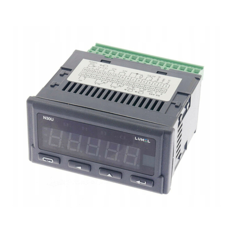
The view of the N31U meter is shown in Fig. 1.
2 Meter set
The meter set includes:
•Meter N31U – 1 pc
•Clamps to fix in the panel – 4 pcs
•Seal – 1 pc
Fig. 1: View of the N31U meter.

N31U Service manual 5
3 Basic requirements, operational safety
In terms of a user safet , the N31U meter meets the requirements of the EN61010-1
standard for the devices intended for use in facilities compliant with the third categor of
installations.
Comments concerning safety
•Assembl and installation of the electrical connections should conducted onl b a
person authorised and certificated to perform assembl of electric devices.
•Alwa s check the connections before turning the meter on.
•The meter is designed to installation and usage in the industrial electromagnetic
environment.
•A switch or a circuit-breaker should be installed in the building or facilit . It should
be located near the device, easil accessible b the operator, and suitabl marked.
•Removal of the meter electronics during the warrant period voids the warrant .
4 Installation
4.1 Installation method
The N31U meters are designed to be mounted in a panel. Prior to installation a 92 +0.6 x
45+0.6 mm slot must be made in the panel. The maximum thickness of the panel material
cannot exceed 6 mm. The meter should be mounted from the front of the panel with
disconnected meter connection strips.
Before inserting the meter into the panel check the correct position of the meter seal and
make sure that the edges of the panel are not sharp what could damage the seal. After
inserting the meter into the slot, mount it with the mounting brackets provided in the meter
set (Fig. 2).
Fig. 2: Meter fixing.

N31U Service manual 6
Electrical connections of the meter should be made with the wires with the cross-section
up to 2.5 mm2. Detachable sockets with the plugs of 5.08 mm pitch can be used for the
connections.
The external dimensions of the meter are shown in Fig. 3.
4.2 E ternal connection diagram
The meter's electrical connections must be made with wires whose cross-section does not
exceed 1.5 mm2 for terminals numbered 1 to 10 (lead-in grid of 3.81 mm) and 2.5 mm2 for
terminals numbered 11 to 18 (lead-in grid of 5.08 mm).
The view of the meter from the connectors' side is shown in Fig. 5. The upper terminal strip
is optional and depends on the accessories of the meter.
The circuits of successive groups of the terminals are separated from each other, as
shown in Fig. 4.
Fig. 3: Meter overall dimensions.
Fig. : Galvanic isolation of the N31U meter.
Suppl
Measuring inputs, output 10/24 V d.c.

N31U Service manual 7
Note: Unused terminals of the terminal strips must not be connected to any signals.
Detailed description of the signals is shown in the table below, and the connection of the
measuring signals is shown in Fig. 6.
Terminal Function Description
1, 2, 3, 4,
5, 7, 8
Measuring inputs Measuring inputs for connecting sensors, transducers or
output signals from the other devices. Examples of the
connections are shown in Fig. 6.
6, 9 Suppl output Auxiliar suppl ing output (24 V) for suppl ing the
potentiometers, transducers, e.g. head-mount transducers
supplied b a current loop. Maximum current carr ing
capacit of the output is 30 mA.
11, 12, 13 RS-485 RS-485 interface signals
Fig. 5: Signals on the terminal strips.

N31U Service manual 8
14, 15 Alarm Alarm output, which is NO rela contact.
16, 17, 18 Power suppl Meter power suppl connection. Depending on the power
suppl voltage range, use connectors 17-18 or 16-17.
Note: Connecting the power supply to connectors
16-18 will damage the meter!
The connection of the basic measured signals is shown below. The inputs not used in the
configuration should be left unconnected.

N31U Service manual 9
4.3 E amples of connecting the e ternal transducers
Connections of the head-mount transducers when the transducers are supplied directl
from the N31U meter are shown below. In the case of the transducers with a voltage
output, the maximum current carr ing capacit of the auxiliar suppl output is 30 mA and
the auxiliar suppl source is onl active for selected input ranges of 10V, 20MA and
Pot10V.
5 Service
The N31U meter user interface includes an LCD displa and the buttons which enable to
displa the measuring value, a full configuration and setting of the meter or modification of
the parameters.
After turning the meter on the displa shows the name of the meter and the software
version. If there is no error during meter initialization process, the meter will switch to
displa ing the measuring value. If during the initialization an irregularities or deviations
are detected, than a message with information about a detected error will be displa ed
(see point 6 - Error codes).
5.1 Description of the frontal plate
View of the front panel of the meter is shown in Fig. 6. The LCD displa with backlight and
4 buttons are on the front panel. The description of the displa fields is shown below. The
button functions are shown in the section 5.2.

N31U Service manual 10
Designation Description
L1 The upper (main) line of the displa has 6 characters used to displa a
measuring value or a parameter value during the meter configuration.
L2 The lower (auxiliar ) line of the displa has 5 characters used to displa a
measuring value, not converted b the individual characteristic or,
according to configuration, a unit or current time.
Z1 Measuring value averaging indicator. Illuminated averaging indicator
informs that the set measuring value averaging period has not elapsed et.
ALI Alarm status field. This field contains the indicator informing about the
alarm status. Illuminated alarm indicator means that an alarm event is in
progress and the rela corresponding to the alarm is activated. Flashing
s mbol means that the alarm state is saved (if the alarm memor is
activated).
B1...B4 Meter operation buttons. The description of the button functions and their
various combinations are shown in section 5.2.
VO Indicator informing that the auxiliar suppl output voltage is stable - the
output voltage value is stable and within the specified range (see technical
data).
The lower line of the displa can be configured to displa the unit. The available units with
the corresponding value in the register 4008 of the MODBUS protocol are shown below.
Value in the
register 4008
(setting)
Unit
Value in the
register 4008
(setting)
Unit
Value in the
register 4007
(setting)
Unit
0 ----- 20 kvarh 40 h
1 mV 21 Mvarh 41 m3
2 V 22 VAh 42 obr
3 kV 23 kVAh 43 pcs
4 mA 24 MVAh 44 imp
Fig. 6: Front panel of the meter.

N31U Service manual 11
5 A 25 Hz 45 rps
6 kA 26 kHz 46 m/s
7 W 27 W47 l/s
8 kW 28 kW48 rpm
9 MW 29 ºC 49 m/min
10 var 30 ºF 50 l/min
11 kvar 31 K 51 szt/h
12 Mvar 32 % 52 m/h
13 VA 33 %rh 53 km/h
14 kVA 34 pH 54 m3/h
15 MVA 35 kg 55 kg/h
16 Wh 36 bar 56 l/h
17 kWh 37 m
18 MWh 38 l
19 varh 39 s
5.2 Buttons' functions
Cancel button:
•Exiting the menu and exit to the main screen.
•Exiting a lower level of the menu and return to a higher level.
•Canceling changing the set value (when editing the parameter value)
Digit change button:
•Navigating the menu - decreasing the items of the menu.
•Decreasing the controlled quantit while editing a parameter and
setting selection from the list of settings, e.g. alarm t pe.
•Changing the controlled digit when setting numerical parameters.
•Pressing the button during a normal operation displa s a minimum
value for 2 seconds, then the displa returns to displa ing a measuring
value.
Increase value button:
•Navigating the menu - increasing the items of the menu.
•Increasing the value of the selected parameter or increasing the value
of a digit when changing the numerical value.
•Pressing the button during a normal operation displa s a maximum
value for 2 seconds, then the displa returns to displa ing a measuring
value.

N31U Service manual 12
Confirm button:
•Entering the programming mode (holding down the button for at least 3
seconds).
•Navigating the menu - entering the parameter value editing mode or
entering the selected lower level of the menu.
•Accepting the changed parameter value.
Deleting minimum value. DELMIN message is displa ed after deleting.
Deleting maximum value. DELMAX message is displa ed after deleting.
Deleting alarm memor - hold down the buttons for 3 seconds. ClrAL message
will be displa ed after deleting alarm memor .
All the events of deleting of saved minimum, maximum values and alarm activation
memor are indicated b the meter b displa ing an appropriate message.
5.3 Programming meter parameters
Programming meter parameters is possible via the RS485 interface and b direct edition of
the parameters using the buttons and the meter displa .
Direct programming process is eas thanks to meter menu, which includes the settings
grouped into sections with all parameters related to a given functionalit , e.g. all
parameters of the serial interface are grouped in the menu .
Switching from a normal operation to meter menu is possible b pressing and holding for
at least 3 seconds the confirm button . If access to change the parameters is
password protected, the user will be requested to enter the access password before
entering the menu. Entering an incorrect password will allow to enter the menu but it will
be not possible to change the parameters - parameters monitoring mode. Entering a
correct password will allow to move to a programming matrix, the menu after entering the
programming mode is shown below.
Fig. 7: View of meter menu.

N31U Service manual 13
While navigating the meter main menu with the groups of the parameters, the upper line of
the displa shows the name of the group and the lower line continuousl displa s the word
MENU. After entering the group of the parameters (after pressing the confirm button), the
upper line displa s the value of a given setting and the lower line shows the name of the
parameter which value is displa ed in the upper line. Sample view of the selection of the
measured input signal t pe is shown in Fig. 8.
The buttons allow to navigate the menu of the meter. After selecting the
group of the parameters which configuration is to be changed, press the confirm button to
move to the parameters of the group. The parameter which value is to be modified is
selected the same wa as the selection of the group. To cancel the parameter change,
press the cancel button to exit the parameter changing mode or the parameter
group. The transducer will automaticall exit the programming mode and return to
displa ing the measuring value if no button is pressed for 30 seconds during programming.
The programming matrix is shown below.
Input t pe selection
(measuring signal or
sensor).
Standard averaging -
number of the
measurements to be
averaged.
Moving window
method averaging -
number of the
measurements to be
averaged (window
width).
Compensation
method selection -
important parameter
for temperature
measurement
sensors
(thermoresistors and
thermocouple
sensors).
Compensation value
for manual
compensation
method of wires
resistance or
terminals
temperature.
Mathematical
function selection
based on which the
measuring value
should be converted
Enabling or disabling
the individual
characteristic.
Number of points of
the individual
characteristic.
Measuring value -
point no. 1.
Expected value for
the measuring value
X1.
Measuring value -
point no. 2.
Expected value for
the measuring value
X2.
... ... Measuring value -
point no. 32.
Expected value for
the measuring value
X32.
Fig. 8: View of menu when setting a parameter.
Parameter
which can be configured
Current value
of a setting

N31U Service manual 14
Selection of main
displa ed value.
Minimum value on
the displa . For
values lower than
this value, a lower
overrun message is
displa ed.
Maximum value on
the displa . For
values higher than
this value, an upper
overrun message is
displa ed.
Resolution - position
of the decimal point.
The unit which can
be displa ed in the
lower line (when
displa ing the
measuring value).
Function of a lower
line of the displa -
selection of a
quantit displa ed in
the lower line.
Selection of quantit
controlling the alarm
state.
Selection of alarm
t pe.
Alarm state change
lower threshold.
Alarm state change
upper threshold.
Alarm activation
dela .
Alarm deactivation
dela .
Active alarm
memor .
Meter network
address.
Transmission frame
t pe - data format.
Baud rate.
Password to protect
against settings
modification.
Restore default
settings
5.3.1 How to change quantity of a selected parameter
To increase the value of the selected parameter, press the button . Pressing the
button will increases the currentl set digit b 1 and after reaching the value 9, pressing
the button will set the value 0. After setting the required value of a digit, move to the next
digit b pressing the button . After setting the required parameter value, press the
confirm button to accept the entered value or the cancel button to cancel
the parameter change and return to the previous value of the parameter. It is possible to
change a sign of the entered value during setting the last digit (most significant).
There are two steps to change the floating point values. The first step is to set the digits
and a sign in accordance with the algorithm described above. The second step is set the
position of the decimal point after pressing the confirm button. The buttons
are used to set the position of the decimal point. Press the confirm button after setting the
decimal point on the desired position.
Entering an incorrect value of a given parameter causes that the new value is not
accepted and the parameter will automaticall have the previous value.

N31U Service manual 15
To change the parameters other than numerical select the appropriate setting from the
parameter list using the buttons . After selecting the appropriate setting,
press the confirm button to use the setting or the cancel button to return to
the previous value and exit the parameter change mode.
5.3.2 Programmable meter parameters, default parameters
The N31U meters have a number of programmable parameters, which enable the meter to
be adapted to the requirements of application. The parameters grouped according to the
menu are shown in the tables below.
Table 1
Parameter
symbol Description Range o changes
T pe of connected input signal - measuring
input t pe selection.
De ault: 10V
Pt100 – PT100
Pt1000 – PT1000
REZ–L – resistance measurement, range of 400 W
REZ–H – resistance measurement, range of 4,000 W
tC–E – thermocouple t pe E (NiCr-CuNi)
tC–J – thermocouple t pe J (Fe-CuNi)
tC–K – thermocouple t pe K (NiCr-NiAl)
tC–N – thermocouple t pe N (NiCrSi-NiSi)
tC–R – thermocouple t pe R (PtRh13-Pt)
tC–S – thermocouple t pe S (PtRh10-Pt)
60MV – voltage measurement, range 60 mV
150MV – voltage measurement, range 150 mV
300MV – voltage measurement, range 300 mV
10V – voltage measurement, range 10 V
20MA – current measurement, range 20 mA
4_20MA – current measurement, range 4...20 mA
Pot10V – potentiometer measuring, measuring range 10 V,
scaled as a function of the auxiliar output voltage value.
Time of a single measurement as a multiple of
100 ms (200 ms for enabled automatic
compensation for RTD sensors or resistance
measurement).
De ault: 10
1...600
Number of the item for moving window method
averaging. Each item is a measurement taken
in SAVG time.
De ault: 1
1...3600
Selection of resistance compensation method
of the connection cables during resistance or
temperature measurements using RTD
sensors or terminals temperature
compensation for temperature measurement
with thermocouple sensors.
De ault: AUTO
AUTO – automatic compensation of the terminals
temperature is enabled (for measurements using the
thermocouples) or cables resistance compensation for
resistance measurements (a 3-wire s stem is required).
MANUAL – manual compensation of the measuring value.
The temperature value of the terminals is determined b
MCOMP setting for measurements using the thermocouples.
The resistance value of connecting cables is determined b
MCOMP setting for resistance measurements.
The resistance of the connecting cables or
terminals temperature during manual
compensation (MANUAL).
De ault: 0
-30...70 – for the input set to measure using the
thermocouples.
0...20 – for resistance measurement or temperature
measurement using the RTD sensors.

N31U Service manual 16
Mathematical function selection which should
be applied for the measuring value. The
mathematical function is applied before the
value is converted b the individual
characteristic.
De ault: NONE
NONE – no additional mathematical operations.
Sqr – measuring value is squared.
Sqrt – square root of the measuring value.
Inv – reciprocal of the measuring value.
InvSq – reciprocal of the measuring value is squared.
InvSt – square root of reciprocal of the measuring value.
Table 2
Parameter
symbol Description Range o changes
Enable or disable the individual characteristics.
The OFF setting makes possible to disable the
individual characteristic function.
De ault: OFF
OFF – individual characteristic disabled.
ON – individual characteristic enabled.
Number of points of the individual
characteristic.
De ault: 2
2...32
The first point of the individual characteristic -
the value measured directl or the value
converted b the mathematical function.
De ault: 0
-99999...999999
The first point of the individual characteristic -
expected value for the value X1.
De ault: 0
-99999...999999
...
Last possible point of the individual
characteristic.
De ault: 31
-99999...999999
Last possible point of the individual
characteristic – expected value for X32.
De ault: 31
-99999...999999
Table
Parameter
symbol Description Range o changes
Selection of the main value displa ed on the
top line of the displa .
De ault: VALIND
VALIND – averaged value of the measuring quantit ,
converted b the mathematical functions and converted b
the individual characteristic.
MIN_MW – minimum value registered during the averaging
period of the moving window method (during the window)
MAX_MW – maximum value registered during the averaging
period of the moving window method (during the window)
Note: The window length can be programed (MAVG
parameter).
Displa narrowing lower threshold. If the value
to be displa ed is below the threshold, the
lower limit s mbol is displa ed
.
De ault: -99999
-99999...999999
Displa narrowing upper threshold. If the value
to be displa ed is above the threshold, the
upper limit s mbol is displa ed
.
De ault: -99999
-99999...999999

N31U Service manual 17
Resolution, displa format as the position of
the decimal point.
De ault: 0000.00
000000
00000.0
0000.00
000.000
00.0000
0.00000
AUTO – automatic position of the decimal point for maximum
possible resolution.
Value selection which should be displa ed in
the lower line of the displa if the displa ing a
unit is selected as a function .
De ault: "-----"
The list of available units is provided in Section 5.1.
Selection of the parameter displa ed in the
lower line of the displa .
De ault: UNIt
UNIt – unit
noInd – measuring value not converted b the individual
characteristic (averaged based on the settings)
clock – current time.
Table 4
Parameter
symbol Description Range o changes
Input value controlling the alarm.
De ault: VALIND
VALIND – measuring value, averaged, converted b the
mathematical functions and the individual characteristic.
VALAVG – measuring value, averaged, not converted b the
mathematical functions or the individual characteristic.
VAL – measuring value. As above but not averaged.
Alarm t pe (see section 5.4.3) De ault: H-oFF
n-on – normall enabled
n-oFF – normall disabled
on – enabled
oFF – disabled
H-on – permanentl enabled (manuall )
H-oFF – permanentl disabled (manuall )
REG – the state controlled b the MODBUS protocol register.
Alarm state change lower threshold. De ault: 10
-99999...999999
Alarm state change upper threshold. De ault: 20
-99999...999999
Alarm activation dela - the duration in
seconds of the alarm state before activating
the alarm rela .
De ault: 0
0...900
Alarm deactivation dela - the duration in
seconds the state without the alarm before
deactivating the alarm rela .
De ault: 10
0...900
Alarm signalization latch. When the function is
enabled, after the alarm event ends, the
displa indicator informing about the alarm
status will be flashing signaling the alarm until
it is canceled b a combination of buttons
or via the RS-485 interface.
De ault: OFF
ON – alarm memor is activated.
OFF – alarm memor is deactivated.

N31U Service manual 18
Table 5
Parameter
symbol Description Range o changes
MODBUS network meter address
De ault: 1
1...247
The transmission frame t pe of RS-485
interface. Setting the parit bits and the
number of stop bits.
De ault: F8N1
F8N1
F8N2
F8O1
F8E1
RS-485 interface baud rate.
De ault: 9.6k
2.4k – 2400 b/s
4.8k – 4800 b/s
9.6k – 9600 b/s
14.4k – 14400 b/s
19.2k – 19200 b/s
28.8k – 28800 b/s
38.4k – 38400 b/s
57.6k – 57600 b/s
115.2k – 115200 b/s
Table 6
Parameter
symbol Description Range o changes
Setting the current time. Confirmation of the time
resets the seconds counter.
De ault: (not applicable)
00:2359
Setting the current date in YYYY.MM.DD format,
where:
YY – ear.
MM – month.
DD – da of the month.
De ault: (not applicable)
00.01.01...99.12.31
Automatic change of DST and inversel
De ault: OFF
OFF – automatic time change disabled.
ON – automatic time change enabled.
Password to access the meter configuration. When
the set value is different from zero, each attempt to
enter the menu of the meter will require entering a
password. In case of providing an incorrect
password, it will be possible to enter the menu in the
monitoring mode without a possibilit of make an
changes.
De ault: 0
0...9999
Restore default settings. Selecting YES setting will
restore all settings to the default settings and set
FACt setting to NO.
De ault: NO
NO – do nothing.
YES – restore default settings (factor ).

N31U Service manual 19
5.4 Meter functions
5.4.1 Measurement
The N31U meters continuousl measure the selected quantit , which is averaged in a
given period, and convert it according to the selected mathematical function, and then
convert it based on the individual characteristic. When shortening the measurement time, it
needs to be considered that the shorter the measurement time, the greater the influence of
noise on the measuring value, and therefore the lower the stabilit of indications.
All measuring parameters are available via the RS-485 interface, including the basic
measuring values such as resistance and resistance of cables for the measurements using
RTD sensors or measured voltage for the thermocouple sensors. Additionall , in order to
facilitate a control of the measuring signals, the intermediate measuring values, such as
values not converted b the individual characteristic or not averaged, were also stored in
MODBUS interface registers (see Section 5.6.4).
The measuring value can also be limited b the user b defining the minimum and
maximum measuring value. Exceeding set lower threshold of the measurement (the
measuring value lower than the set limit value) causes to displa information about
exceeding the lower limit, and exceeding set upper threshold of the measuring range
(measuring value greater than the set limit value) causes to displa information about
exceeding the upper limit.
As mentioned above, the measuring value is several times recalculated. The sequence of
operations is shown in Figure 9.
Note: The parameter is unique or the analog output and or each o the
alarms, it allows to individually select the parameter controlling the output.
Fig. 9: Measurement recalculation.

N31U Service manual 20
5.4.1.1 Averaging the measuring quantity
The measuring value is averaged in two stage process. The first stage of averaging - the
arithmetic mean is calculated from the indicated number of measurements defined b
SAVGt parameter. The parameter also determines the time of a single measurement
because one measurement takes 100 ms, e.g. for measurement of thermocouple sensor
t pe K and the SAVG parameter set to 10, the time of a single measurement will be one
second. The next stage of averaging is the averaging using the moving window method,
where the individual measurements are stored in the arra , so when adding a new item to
the arra it replaces the oldest item. The average value is calculated ever time a new
element is stored in the arra . The number of arra elements (window length) is defined b
the user in meter configuration (MAVG parameter). The number of arra elements
determines the averaging period, because it is a multiple of the time of a single
measurement, e.g. for the previous example, setting the MAVG parameter to 60 will set
the averaging time at 60 seconds, and the value will be updated ever 1 second, i.e. ever
time a single measurement is done.
5.4.1.2 Minimum and maximum measuring values
The N31U meter continuousl measures the signal on the indicated input. The measuring
value (displa ed) is constantl monitored, if the measuring range is not exceeded during
the measurement. If the value is smaller than the current minimal value, then the new
minimal value is saved. If the measuring value (displa ed) is higher than the current
maximum value, the new maximum value is stored. The minimum and maximum value is
available via the interface and from the panel of the meter. Press the button to
displa the minimum value. Press the button to displa the maximum value. The
minimum / maximum value is displa ed for 2 seconds, then the meter automaticall
returns to displa ing the measuring value.
Reset of the minimum / maximum value can be done via the interface or directl using the
meter ke pad. Press a combination of buttons to reset the minimum value,
and press a combination of buttons to reset the maximum value. Each reset
of the minimum or maximum value using the buttons is confirmed b a message - an
example the message is shown below.
Fig. 10: The message after resetting the
maximum value.
Other manuals for N31U
1
Table of contents
Other Lumel Measuring Instrument manuals
Popular Measuring Instrument manuals by other brands

P3 International
P3 International P4460 Operation manual

SATA
SATA AE5809 user manual

ASCO POWER TECHNOLOGIES
ASCO POWER TECHNOLOGIES SIGMA Hand-held quick start guide

VOLTCRAFT
VOLTCRAFT VC-330 operating instructions

Rhopoint
Rhopoint NOVO-GLOSS operating instructions

LumaSense technologies
LumaSense technologies IMPAC IN 9 plus manual