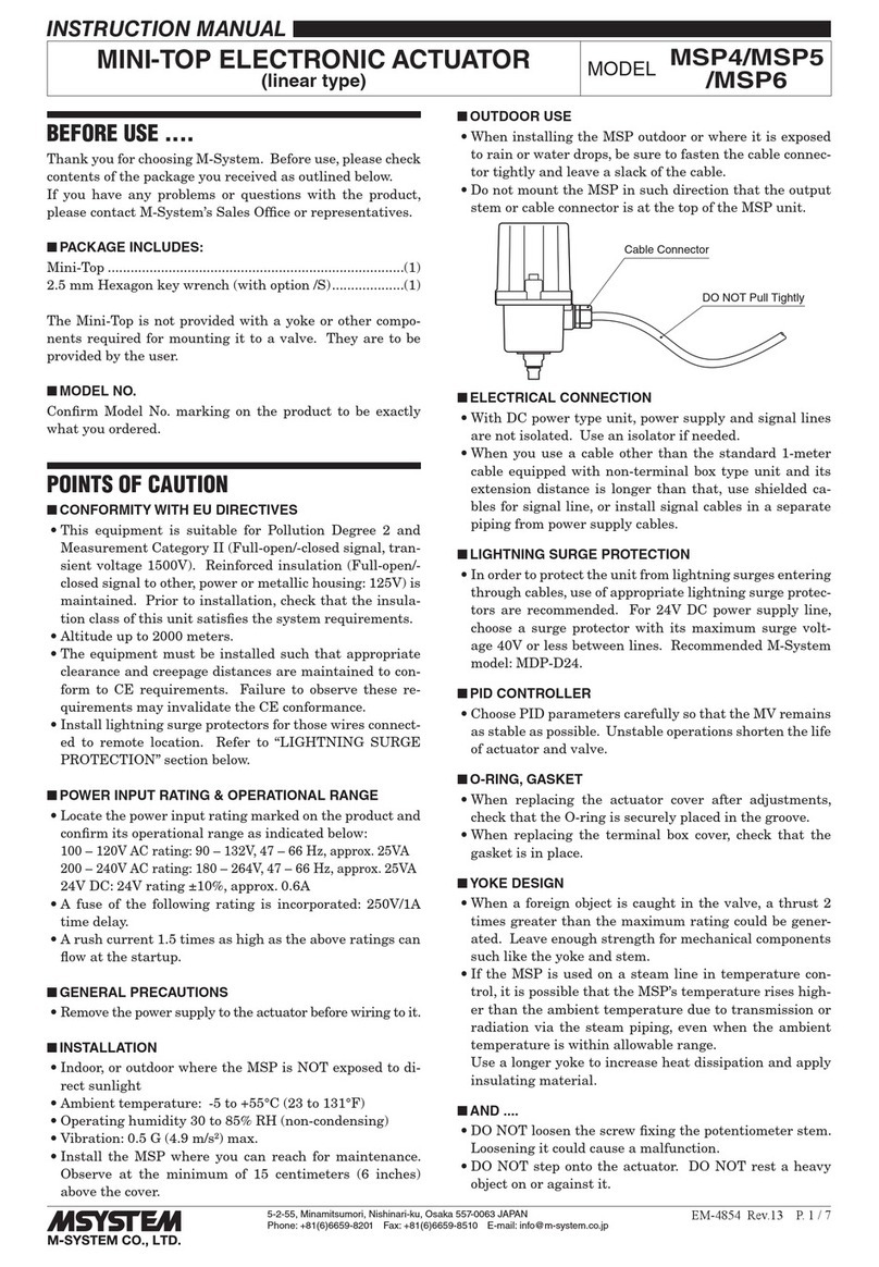
7. ADJUSTMENT PROCEDURE
7. 1. MANUAL OPERATION
The MSPxC can be manually controlled regardless of the
communications status. Turn the SW5-1 ON to enable the
manual operation mode. The SW8 and SW7 are used for
control.
Table 2. SW5 setting, manual operation
SW5 OFF ON
1
Control via com-
munications
Manual operation
2 Invalid 0% manual control command
3 Invalid 100% manual control command
4 Unused
Turning both SW5-2 and -3 is invalid. The actuator operation
stops.
SW8: The stem moved toward 0% position while pressing
this switch.
SW7: The stem moved toward 100% position while pressing
this switch.
7. 1. 1. GENERAL PROCEDURE
After installing the valve and actuator, go to adjustments in
order of Zero, Span, and the seal-spring.
7.1.2. ZERO & SPAN
1) Zero Adjustment: Turn the power supply on and set the
SW5-1 and -2 ON (OFF for the others on the SW5). This
turns the actuator into the manual operation mode and
automatically controls the stem toward the 0% position.
Once the stem reaches the position, adjust either the ac-
tuator with the Zero potentiometer or the mechanical po-
sition of the valve stem connection so that the actuator’s
extended position (valve’s retracted position) is adequate.
If extra sealing pressure by the seal-spring is required,
push in the actuator stem referring to Table 3.
2) Span Adjustment: Turn the power supply on and set the
SW5-1 and -3 ON (OFF for the others on the SW5). This
turns the actuator into the manual operation mode and
automatically controls the stem toward the 100% posi-
tion.
Once the stem reaches the position, adjust either the ac-
tuator with the Span potentiometer or the mechanical
position of the valve stem connection so that the actua-
tor’s retracted position (valve’s extended position) is ad-
equate.
For three-way valves, the sealing pressure can be adjust-
ed to be applied in the direction where the output stem
is fully retracted (not available for the MSP4C). Adjust-
ment procedure is the same for Zero.
3) With 0% input again, check that the Mini-Top is at the
fully extended position. If the position is shifted, go
through the above procedure again.
Note 1: There is only minimal effect of span adjustment to
zero point, thus the stem position shifts very little
at the extended side when the span potentiometer is
turned.
Note 2: With the stroke narrower, hunting (the motor repeats
changing direction) can happen more often. Adjust
Deadband in such cases.
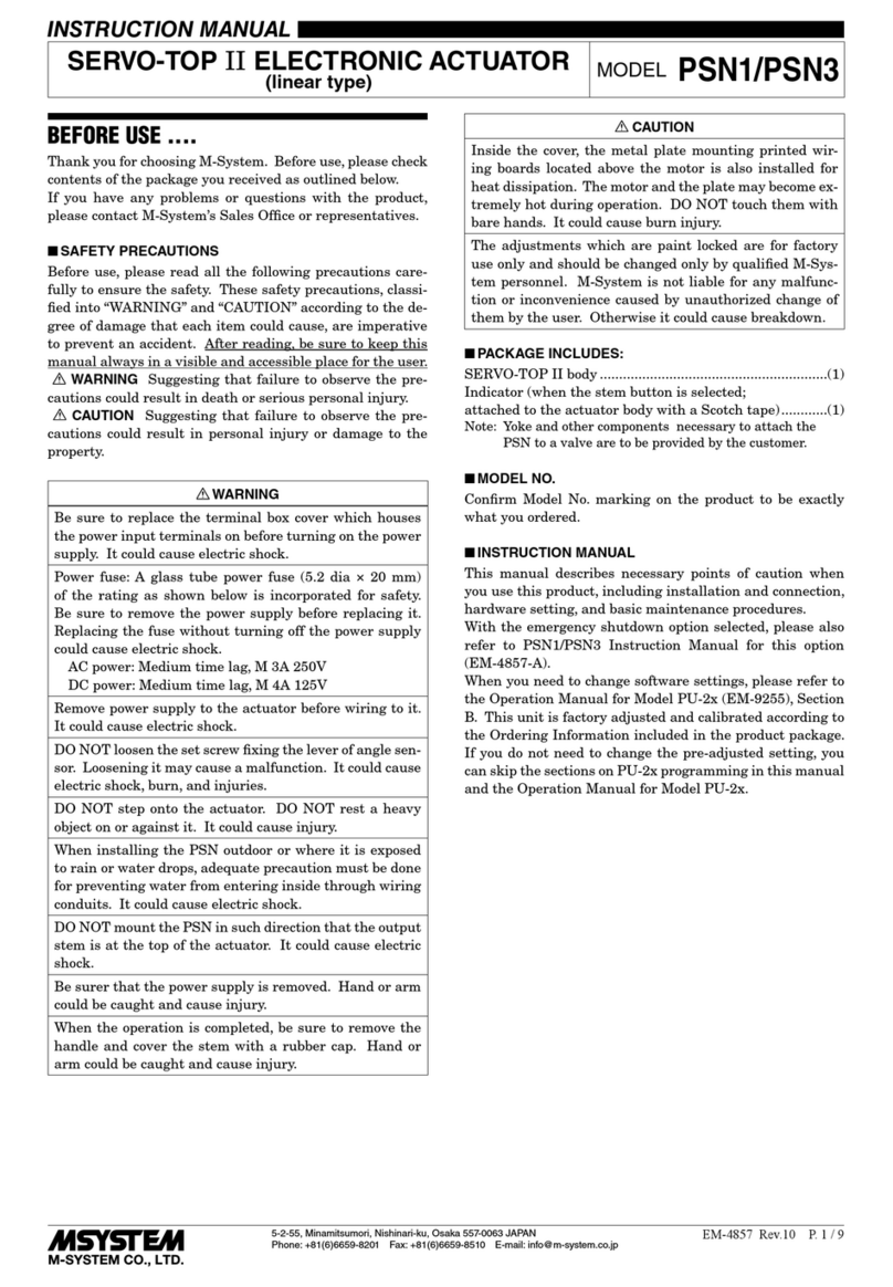
Output Stem
Seal Spring Division
Figure 10. Seal-spring
Table 3. Seal-spring pressure
MODEL
SPRING
CONTRACTION
(mm)
CONTACT*
PRESSURE
(N / lbs)
SEALING
PRESSURE
(N / lbs)
MSP4C-x3 0.5 147/33 98/22
MSP4C-x4 1.0 300/67 250/56
MSP4C-x7 1.0 686/154 294/66
MSP5C-x3 0.5 150/34 110/25
MSP5C-x4 1.0 294/66 216/49
MSP5C-x7 1.0 686/154 294/66
MSP6C-x3 1.0 588/132 441/99
MSP6C-x4 1.0 1170/263 882/198
MSP6C-x6 1.5 2350/529 1170/263
* The minimum pressure required to contract the spring.
Note: Graduations by 1 millimeter increments are marked
on the stem. For example, with MSP4C-x7, the sealing
pressure reaches approx. 490 N at 0.5 mm, 686 N at 1
mm.
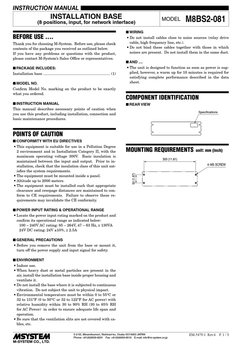
7.1.3. DEADBAND
‘Deadband’ is provided in 0.2% increments from 0.1%, 0.3%,
0.5%, .... with the fractions dropped.
SW4 DEADBAND (%)
0 0.1
1 0.3
2 0.5
3 0.7
4 0.9
5 1.1
6 1.3
7 1.5
8 1.7
9 1.9
-0.3% -0.2% -0.1% TARGET +0.1% +0.2% +0.3%
0.1%
0.3%
0.5%
Figure 11. Deadband
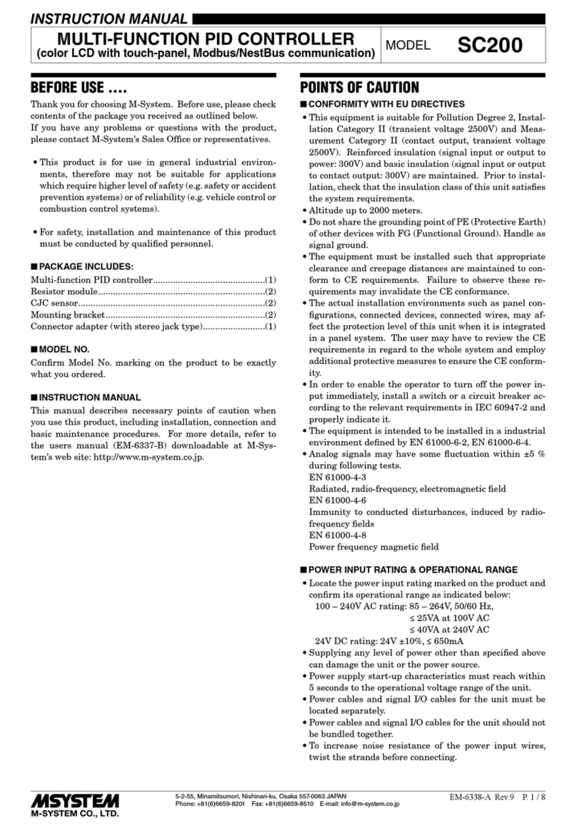
7.1.4. RESTART LIMITING TIME
Set the restart limiting time as follows:
SW6-1 SW6-2
RESTART LIMITING TIME (sec.)
OFF OFF 0
ON OFF 1.5
OFF ON 5
ON ON 10
MSP4C / MSP5C / MSP6C
5-2-55, Minamitsumori, Nishinari-ku, Osaka 557-0063 JAPAN
Phone: +81(6)6659-8201 Fax: +81(6)6659-8510 E-mail: info@m-system.co.jp
EM-4862 Rev.1 P. 6 / 9
