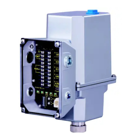
M-system SC200W User manual

5-2-55, Minamitsumori, Nishinari-ku, Osaka 557-0063 JAPAN
Phone: +81(6)6659-8201 Fax: +81(6)6659-8510 E-mail: info@m-system.co.jp
EM-6346-A P. 1 / 7
INSTRUCTION MANUAL
MULTI-FUNCTION PID CONTROLLER
(color LCD with touch-panel, Modbus/NestBus communication,
expansion module function)
MODEL SC200W
BEFORE USE ....
Thank you for choosing M-System. Before use, please check
contents of the package you received as outlined below.
If you have any problems or questions with the product,
please contact M-System’s Sales Office or representatives.
• This product is for use in general industrial environ-
ments, therefore may not be suitable for applications
which require higher level of safety (e.g. safety or accident
prevention systems) or of reliability (e.g. vehicle control or
combustion control systems).
• For safety, installation and maintenance of this product
must be conducted by qualified personnel.
■PACKAGE INCLUDES:
Multi-function PID controller.............................................(1)
Resistor module...................................................................(2)
CJC sensor...........................................................................(2)
Mounting bracket................................................................(2)
Connector adapter...............................................................(1)
■MODEL NO.
Confirm Model No. marking on the product to be exactly
what you ordered.
■INSTRUCTION MANUAL
This manual describes necessary points of caution when
you use this product, including installation, connection and
basic maintenance procedures. For more details, refer to
the users manual (EM-6346-B) downloadable at M-Sys-
tem’s web site: http://www.m-system.co.jp.
POINTS OF CAUTION
■POWER INPUT RATING & OPERATIONAL RANGE
• Locate the power input rating marked on the product and
confirm its operational range as indicated below:
100 – 240V AC rating: 85 – 264V, 50/60 Hz,
≤ 25VA at 100V AC
≤ 40VA at 240V AC
24V DC rating: 24V ±10%, ≤ 650mA
• Supplying any level of power other than specified above
can damage the unit or the power source.
• Power supply start-up characteristics must reach within
5 seconds to the operational voltage range of the unit.
• Power cables and signal I/O cables for the unit must be
located separately.
• Power cables and signal I/O cables for the unit should not
be bundled together.
• To increase noise resistance of the power input wires,
twist the strands before connecting.
■GENERAL PRECAUTIONS
• Before you remove the unit, turn off the power supply and
input signal for safety.
• Do not disassemble or modify the unit in any way. Doing
so may result in a fire or an electrical shock.
• Do not block the unit’s ventilation openings or use it in
areas where heat accumulates.
Additionally, do not store or use it under high-tempera-
ture conditions.
• Do not use this unit in an environment where flammable/
corrosive gases are present.
• Do not store or use this unit in locations subject to direct
sunlight, or where excessive dust, dirt or metal particles
are present.
• This unit is a precision instrument. Do not store or use it
where large shocks or excessive vibration can occur.
• Do not store or use this unit in environments subject to
chemical evaporation (such as that of organic solvents),
or where there are chemicals and/or acids present in the
environment.
• Do not use paint thinner or organic solvents to clean this
unit.
• Observe the environmental conditions when using this
unit.
• Wait at least 30 seconds before turning on the power sup-
ply after it was turned off.
■ENVIRONMENT
• Indoor use.
• This unit is designed to be mounted on a vertical panel. It
is not suitable for a slanted or a horizontal panel surface.
• Environmental temperature must be within -5 to +55°C
(23 to 131°F) with relative humidity within 5 to 90% RH
in order to ensure adequate life span and operation.


SC200W
5-2-55, Minamitsumori, Nishinari-ku, Osaka 557-0063 JAPAN
Phone: +81(6)6659-8201 Fax: +81(6)6659-8510 E-mail: info@m-system.co.jp
EM-6346-A P. 2 / 7
■GROUNDING
• Be sure to determine in advance the most stable ground-
ing point in the environment and earth the unit’s FG
terminal and that of connected devices to it in order to
protect the devices from dielectric breakdown.
• Grounding is also effective to eliminate noise that could
cause errors in the unit’s operation.
■LCD PANEL
• The LCD panel’s liquid contains an irritant. If the panel
is damaged and the liquid contacts your skin, rinse imme-
diately the contact area with running water for at least 15
minutes. If the liquid gets in your eyes, rinse immediate-
ly your eyes with running water for at least 15 minutes
and consult a doctor.
• The following phenomena are LCD characteristics, and
NOT a product defect:
- LCD screen may show uneven brightness depending
upon displayed images or contrast settings.
- The LCD screen pixels may contain minute black-and-
white-colored spots.
- The color displayed on the LCD screen may appear dif-
ferent when seen from outside the specified viewing an-
gle.
- When the same image is displayed on the screen for a
long time period, an afterimage may appear when the im-
age is changed. If this happens, turn off the unit and wait
for a while before restarting it.
• To prevent an afterimage:
- Set the screensaver when you plan to display the same
image for a long time period.
- Plan to change the screen image periodically so that the
same image does not remain for the long time period.
• The LCD surface is covered with a protective film at the
factory shipment. Remove it once the unit is installed.
■MINIMIZING NOISE INTERFERENCE TO ANALOG SIG-
NAL CABLES
• Noise entering through the analog signal cables may
cause irregular measurement values, degradation of over-
all accuracy, and malfunction of the product. We recom-
mend that you would conduct wiring to the unit with the
following points of caution.
• Do not install cables close to noise sources (high frequen-
cy line, etc.).
• Do not bind the analog I/O cables together with those in
which noises are present. Do not install them in the same
duct.
■DO NOT APPLY OVERRANGE INPUT
• Do not apply voltages exceeding ±15V across the voltage
input terminals to prevent damage.
• Do not apply currents exceeding ±30mA to the current
input terminals to prevent damage.
■CONNECTOR ADAPTER
• The connector adapter is included in “Stereo jack” type.
• PC Configurator cable (model: COP-US) is required when
configuring.
■CONNECTOR JACK
• The connector jack is covered with a cap. This cap pro-
tects against ingress of moisture or dust. Avoid moisture
ingress into the jack.
• Do not operate the unit if moisture is inside the jack. Pro-
ceed cleaning blowing with air etc.
• To use the configurator cable, remove the cap of the jack
and connect it after the conversion adapter is attached.
• Put the cap on the jack after operating with the configu-
rator cable.
■AND ....
• We recommend use of an UPS to supply power backups.
• The unit is designed to function as soon as power is sup-
plied, however, a warm up for 10 minutes is required for
satisfying complete performance described in the data
sheet.

SC200W
5-2-55, Minamitsumori, Nishinari-ku, Osaka 557-0063 JAPAN
Phone: +81(6)6659-8201 Fax: +81(6)6659-8510 E-mail: info@m-system.co.jp
EM-6346-A P. 3 / 7
COMPONENT IDENTIFICATION
Auto/Man
1. TFT Color LCD with touch panel
Provides operation and engineering views to facilitate monitoring and setting
2. Configurator jack and cap
Connects with a PC where Loop Configuration Builder Software (model: SFEW3E) or PC configurator software (model: SCCFG)
is installed via a PC configurator cable (model: COP-US) and enables programming and parameter setting
3. MV value (DOWN) button
4. Acceleration button
(Accelerates MV signal’s changing speed by pressing simultaneously with MV value button)
5. MV value (UP) button
6. Auto / Man selector (changes the control mode for MV output)
1
2
3456

SC200W
5-2-55, Minamitsumori, Nishinari-ku, Osaka 557-0063 JAPAN
Phone: +81(6)6659-8201 Fax: +81(6)6659-8510 E-mail: info@m-system.co.jp
EM-6346-A P. 4 / 7
INSTALLATION
138
68 [68+72×(n - 1)]
+1
0
+0.7
0
Panel thickness 2.3 – 20
138+1
0
+1
0
■PANEL CUTOUT unit: mm
• Single mounting • Clustered mounting
n = number of units
■CAUTION
• IP55 is ensured for the front panel of the unit mounted
independently according to a panel. Test the sealing at
the mounting surface once the device is installed.
• Set the unit on a vertical surface with its operation but-
tons at the lower side. Mounting in other directions may
cause heat built up inside the unit and shorten its life or
degrade its performance.
• Ensure that there is sufficient space for ventilation in-
side a panel. Do not install above the devices that gener-
ate high heat such as heaters, transformers or resistors.
Leave at least 30 mm (1.2 inch) space above, below and
behind the unit for maintenance purpose (e.g. wiring, re-
moving or installing).
■HOW TO REMOVE THE TERMINAL BLOCK
The terminal block is separable in two pieces. Loosen two
screws on upper and lower of the terminal block to separate.
In order to attach the terminal block, tighten the terminal
fixing screws evenly. (torque: 1.2 N·m)
Be sure to turn off the power supply, input signal and power
supply to the output relays before separating the terminal
block.
Terminal fixing
screws
■HOW TO MOUNT THE UNIT ON A PANEL
1) Remove both mounting brackets.
2) Detach the terminal cover and insert it first and then the
module itself into the cutout hole. (The cover is slightly
wider than the module.)
3) Put and slide the brackets back into the holes at the top
and the bottom and tighten them until the module is
firmly fixed.
Panel Mounting Bracket
■HOW TO REMOVE THE TERMINAL COVER
Insert the minus tip of a screwdriver into each hole at the
four corners of the cover and pull it to the direction as indi-
cated below to separate the terminal cover.

SC200W
5-2-55, Minamitsumori, Nishinari-ku, Osaka 557-0063 JAPAN
Phone: +81(6)6659-8201 Fax: +81(6)6659-8510 E-mail: info@m-system.co.jp
EM-6346-A P. 5 / 7
TERMINAL CONNECTIONS
Connect the unit as in the diagram below or refer to the connection diagram on the terminal cover.
■EXTERNAL DIMENSIONS unit: mm (inch)
*1. For Modbus/TCP only *2. Standard model: 250 mm (9.84”)
Option /3: 300 mm (11.81”)
Option /4: 400 mm (15.75”)
144 (5.67)
164 (6.46)
MOUNTING BRACKETS TERMINAL COVER
72 (2.83) 24
(.94)
*2
210 (8.27) max.
175 (6.89)
Jack cap
1 (.04) 67.5 (2.66)
137.5 (5.41)
14
15
16
17
18
19
20
21
22
23
24
25
26
1
2
3
4
5
6
7
8
9
10
11
12
13
40
41
42
43
44
45
46
47
48
49
50
51
52
28
29
30
31
32
33
34
35
36
37
38
39
7.2 (.28)
27
RJ-45 CONNECTOR
*1
52–M3.5 SCREW
4–M4 SCREW FOR
FIXING TERMINAL

SC200W
5-2-55, Minamitsumori, Nishinari-ku, Osaka 557-0063 JAPAN
Phone: +81(6)6659-8201 Fax: +81(6)6659-8510 E-mail: info@m-system.co.jp
EM-6346-A P. 6 / 7
■CONNECTION DIAGRAM
34
35
36
37
38
39
31
33
32
42
A1
B1
C1
44
43
45
47
46
A2
B2
C2
48
49
50
51
52
29
30
+
+
+
+
–
+
+
+
+
+
–
+
–
Di 1 / Pi 1
Di 2 / Pi 2
Di 4 / Pi 4
Di 3 / Pi 3
Di 5 / Pi 5
Di 6 / Pi 6
Pv 1
UNIVERSAL INPUT
Pv 2
UNIVERSAL INPUT
Ai 1
Ai 2
Ai 3
Ai 4
SENSOR EXC
INPUT
COM
*3. Connect input resistor module (model: REM4) for current input.
*4. Connect CJC sensor for thermocouple input.
*5. Connect input resistor module (model: REM4).
*1. Close across the terminals 27 – 28 when the unit is located at the end of a transmission line (= no cross-wiring).
*2. Close across the terminals 14 – 15 when the unit is located at the end of a transmission line (= no cross-wiring).
■UNIVERSAL INPUT CONNECTION E.G.
RTD
A
B
A
B
C
A
B
C
A
B
C
T/C
CJC SENSOR
C
3
2
1
POTENTIOMETER
max.
min.
*3
*4*5
R
A
B
C
R
29
30
2-Wire
XMTR
+
–
+
–
+
–
+
–
+
–
VOLT / CURRENT
INPUT
PC CONFIGURATOR/
BUILDER SOFTWARE Jack
A
B
B
2-WIRE TRANSMITTER
■DISCRETE INPUT PULSE INPUT CONNECTION E.G.:
Dry contact 1 or 2kΩ
+12V
+
–
16
17
18
19
20
21
22
23
24
25
10
11
3+
4–
+
–
+
+
U(+)
V(–)
–
5
6
7
8
9
12
13
Do 1
Do 2
Do 3
Do 4
Do 5
POWER
Ao 2
Ao 1
Mv 2
Mv 1
Do 6
RUN CONTACT
Modbus/TCP
RJ-45 CONNECTOR
+
–
28
41
40
27
Jumper*1
Shielded Twisted-pair Cable
To Other
NestBus
Devices
SHLD
T4
T1
T2
T3
2
1
14
15
+
–
Jumper*2
Shielded Twisted-pair Cable
To Other
Modbus-RTU
Devices
SHLD
T4
T1
T2
T3
FG
26

SC200W
5-2-55, Minamitsumori, Nishinari-ku, Osaka 557-0063 JAPAN
Phone: +81(6)6659-8201 Fax: +81(6)6659-8510 E-mail: info@m-system.co.jp
EM-6346-A P. 7 / 7
COMMUNICATION CABLE CONNECTIONS
SMLSML
SC200W
*1*1
T1
T2
T3
FG
T1
T2
T3
T4
T1
T2
T3
T4
■Modbus-RTU
■NestBus
R2K-1
SC200WSC200W
CONNECTOR
RS-232-C
RS-485
*1*1
*1. Internal terminating resistor is used when the device is at the end of a transmission line.
*2. For noise protection, connect all shielded cables with each other and ground them at a single dedicated ground point within
the system with grounding resistance of 100 Ω or less. Note that the most suitable ground point differs depending on the system.
Also note that there may be cases where less noise is caused when the shields are left ungrounded.
*2
FG
*2
FG
RS-485
T1
T2
T3
T4
T1
T2
T3
FG
T1
T2
T3
FG
PREPARATION & WIRING TO THE UNIT
■POWER SUPPLY
Confirm the power input rating marked on the product.
1) Remove the terminal cover.
2) Connect power input and protective earth cables to the
power supply terminals.
3) Replace the terminal cover.
■I/O SIGNALS
Refer to the following example of connecting DC signal to
Pv 1 universal input terminals:
1) Turn off the power supply and remove the terminal cover.
2) Connect positive signal wire to the terminal B1 [43] and
negative wire to C1 [44].
3) Replace the terminal cover.
Choose appropriate solderless terminals and wires:
Connection
Terminal screws: M3.5 screw terminal (torque 1.0 N∙m)
Terminal fixing screws: M4 screw terminal (torque 1.2 N∙m)
Screw terminal
Terminal screws: Nickel-plated steel (standard) or stain-
less steel
Terminal fixing screws: Chrome-plated steel
Recommended solderless terminal: R1.25-3.5
LIGHTNING SURGE PROTECTION
M-System offers a series of lightning surge protector for
protection against induced lightning surges. Please contact
M-System to choose appropriate models.
Table of contents
Other M-system Controllers manuals

M-system
M-system M8PP User manual

M-system
M-system SC100 Series User manual

M-system
M-system MSP4C User manual

M-system
M-system MSP5 User manual

M-system
M-system EAR70 User manual

M-system
M-system SC100 Series Instructions for use

M-system
M-system MSP40 User manual

M-system
M-system 18PP User manual

M-system
M-system M8BS2-081 User manual

M-system
M-system PSP10 User manual
Popular Controllers manuals by other brands

Mitsubishi
Mitsubishi FX2N-4AD-PT user guide

Embertec
Embertec Emberpulse Complete user's manual

Enovation Controls
Enovation Controls Murphy PowerCore MPC-10 Operation manual

Altronix
Altronix StrikeIt1V installation guide

LOYTEC
LOYTEC LROC-100 installation instructions

Danfoss
Danfoss AMD 413 installation guide