M-system MSP10 User manual

EM-4887 P. 1 / 17
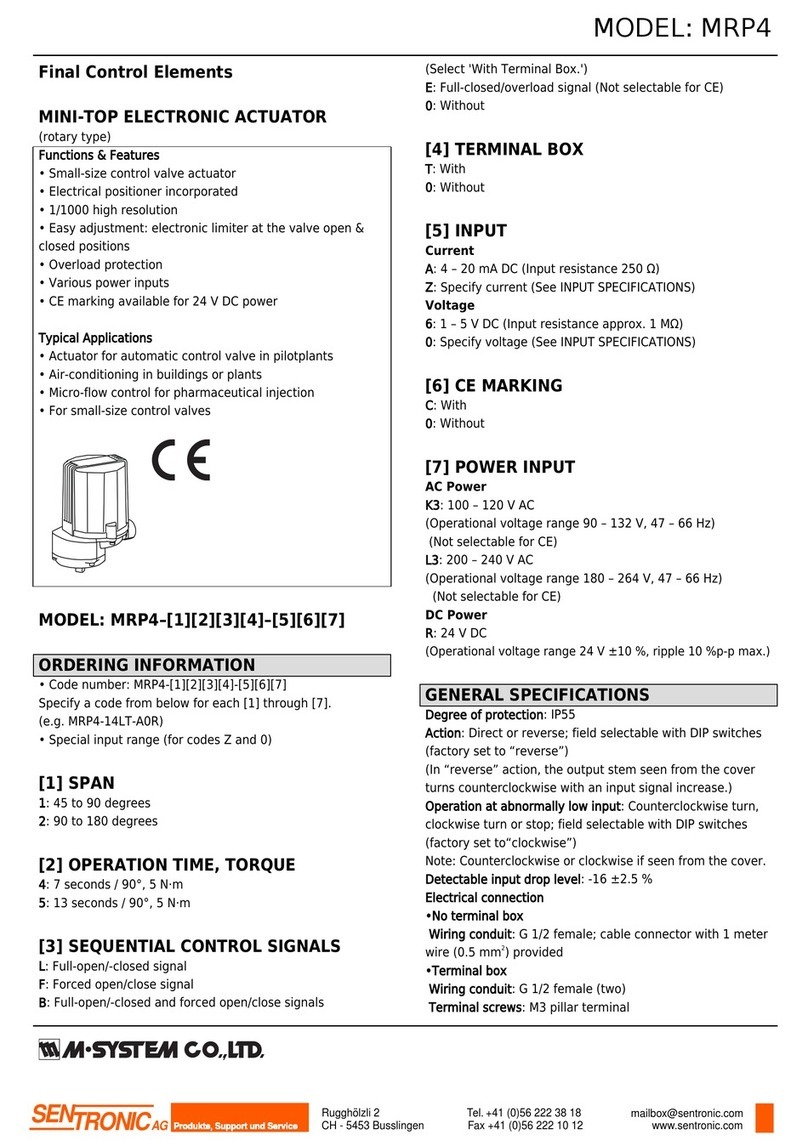
INSTRUCTION MANUAL
STEP-TOP ELECTRONIC ACTUATOR
(Linear type with Auto-setup function; Modbus communication)
MODEL MSP10
BEFORE USE ....
Thank you for choosing M-System. Before use, please check
contents of the package you received as outlined below.
If you have any problems or questions with the product,
please contact M-System’s Sales Office or representatives.
■PACKAGE INCLUDES:
Step-Top Electronic Actuator unit......................................(1)
The Step-Top Electronic Actuator is not provided with a
yoke or other components required for mounting the unit to
a valve. They are to be provided by the user.
■MODEL NO.
Confirm Model No. marking on the product to be exactly
what you ordered.
■SAFETY PRECAUTIONS
Before use, please read all the following precautions
carefully to ensure the safety. These safety precautions,
classified into “WARNING” and “CAUTION” according to
the degree of damage that may be caused by improper use
of the product, are imperative to prevent an accident. Af-
ter reading, be sure to keep this manual always in a visible
and accessible place for the user.
WARNING Suggesting that failure to observe the pre-
cautions could result in death or serious personal injury.
CAUTION Suggesting that failure to observe the pre-
cautions could result in personal injury or damage to the
property.
WARNING
Remove power supply to the actuator before wiring to the
unit. It could cause electric shock.
Do not disassemble or modify the unit in any way.
It could cause electric shock, burn, or injury.
DO NOT step onto the actuator unit.
DO NOT rest a heavy object on or against the unit.
It could cause personal injury.
When installing the actuator unit outdoor or where it
is exposed to rain or water drops, adequate precautions
must be taken for preventing water from entering inside
through wiring conduits. It could cause electric shock.
CAUTION
DO NOT remove the cover of the actuator. It may cause
electric shock or injury.
The adjusters which are paint-sealed are for factory use
only and should be changed only by qualified M-System
personnel. Otherwise it could cause breakdown.
M-System is not liable for any malfunction or inconven-
ience caused by unauthorized changes made by the user.
■INSTRUCTION MANUAL
This manual describes necessary points of caution for han-
dling this product and specifically for installation, wiring,
hardware setting, and basic maintenance of the product.
This unit is factory-adjusted and calibrated according to the
Ordering Information Sheet.
When the user needs to change settings, please also refer to
the Section B of Operation Manual (EM-9255) for the Pro-
gramming Unit (Model: PU-2x).
POINTS OF CAUTION
■POWER INPUT RATING & OPERATIONAL RANGE
• Locate the power input rating marked on the product and
confirm its operational range as indicated below:
24V DC: 24V rating ±10%, approx. 1 A
■HUNTING
• Hunting is a condition in which the output stem is os-
cillated repeatedly and persistently without settling at a
single position.
• The actuator unit must operate at an average duty cycle
of 50% (approx. 13 strokes per minute) or less.
■GENERAL PRECAUTIONS
• Remove the power supply to the actuator before wiring
the unit.
• DO NOT install signal wires and power supply wires to-
gether in one duct because it may cause a malfunction
due to induction noises. Alternatively, use shielded cables
for the input signal wires to prevent interference from
such noises.
• If input signals are to be turned on/off with power sup-
plied to the actuator, be sure to specify the output stem
operation for when abnormally low input is detected.
• DO NOT loosen the screws fixing the potentiometer in-
side the unit.
■INSTALLATION
• Indoor, or outdoor where the unit is NOT exposed to di-
rect sunlight.
• Operating temperature -15 to +66°C (5 to 150.8°F)
• Operating humidity 30 to 90% RH (non-condensing)
• The unit is not designed to withstand all vibrations.
M-System does not guarantee long-term use of the unit
even with small vibrations. Please use the unit only after
evaluating in an actual installation environment. Par-
ticularly, avoid using under the condition where valve
cavitation or water hammer is likely to occur.
• Install the unit where it can be reached for maintenance
and inspection. Be sure to allow at least 20 cm (7.9 inch-
es) clearance above the unit and around the terminal box.
• Keep away from hazardous atmosphere such as explosive
or corrosive gases.
056 222 38 18 mailbox@sentronic.com www.sentronic.com
SENTRONIC AG
MSP10
EM-4887 P. 2 / 17
■PID CONTROL SIGNAL
• Choose PID parameters carefully so that the MV remains
as stable as possible to prevent hunting. Unstable control
shortens the life of actuator and valve.
■TRANSPARENT COVER FOR TERMINAL BOX
• When reattaching the transparent cover after wiring,
make sure that the packing and O ring are securely in
place.
■SCREW TORQUE
• The torque for tightening screws for the transparent cov-
er is between 1.2 – 2 N·m (0.89 – 1.5 ft·lbf). The screws
must be tightened evenly and crosswise in several steps
to prevent uneven clamping.
■YOKE DESIGN
• When a foreign object is caught in the valve, an excessive
torque may be applied to the yoke. Taking it into account,
design the yoke and joint so as to have sufficient margin
in strength.
• When this unit is used in an application such as temper-
ature control of a steam line, the temperature can rise
higher than the ambient temperature due to heat con-
ducted through or radiated from the piping. Use a longer
yoke for effective heat dissipation and apply insulation
material.
■HEATER FUNCTION AT LOW TEMPERATURE
• Apply power voltage when the temperature is 0°C or un-
der. Sensor inside the unit is activated at 0°C or under,
and stepping motor starts heater function.
• A heater is incorporated to use under cold areas.
• Thermostat is incorporated to automatically heat when
27°C (±5°C) (80.6°F (±9°F) or lower, and automatically
stop heating when 39°C (±4°C) (102.2°F (±7.2°F)) or high-
er.
• Be sure to apply power voltage even when the MSP is
unused.
Note. Storage temperature (-29 to 70°C (-20.2 to +158°F))
is for before piping. Once the MSP is piped, the temper-
ature must be in the range of operation temperature.
When using the MSP at the first time in -15°C (5°F), ap-
ply the power voltage and take 30 minutes of hold time
before using the MSP.
■COVER
• No need to remove the cover. All wiring, adjustments,
indicator LEDs are in the terminal BOX. Remove the
transparent cover to work.
• The quality inside the mechanism is stabilized by not re-
moving the cover.
056 222 38 18 mailbox@sentronic.com www.sentronic.com
SENTRONIC AG
MSP10
EM-4887 P. 3 / 17
COMPONENT IDENTIFICATION
Stepping Motor
Cover
Screw Nut
Output stem
Coil
Packing
Packing
Terminal Block
Wiring Conduits (4-G1/2)
Transparent Cover
Terminal Box
Heater
Figure 1. Component identication: MSP40/MSP50
PU-2x modular jack
DIPSwitch ManualOperationButtons
Configuration(Type-C)
UP/CCW
DOWN/CW
POWER INPUT AUTO
SETUP
MOVING
UP/CCW
MOVING
DOWN/CW
COM ALARM
Modbus
CONFIG
(TypeC)
+
−
+
−
a
b
a
b
a
b
INPUT
OUTPUT
UP/CCWSIG.
DOWN/CWSIG.
ALARMSIG.
FE
U(+)
V(−)
DA
DB
DG
POWER
ON
12345678
Figure 2. Component identication: Terminal Box
056 222 38 18 mailbox@sentronic.com www.sentronic.com
SENTRONIC AG
MSP10
EM-4887 P. 4 / 17
STATUS INDICATOR LED AND SIDE DIP SWITCH
■STATUS INDICATOR LED
ID COLOR STAT U S FUNCTION
POWER Green ON Power is ON.
INPUT Green ON Position setpoint input (analog) of 0.37 V or greater is applied.
(With 250 Ω receiving resistor for current input)
AUTO-SETUP Green Blinks at 1 Hz Auto-setup is in process.
Blinks at 5 Hz for 3 sec. Auto-setup has been successfully completed.
MOVING UP/CCW Green ON Output stem is moving up.
MOVING DOWN/CW Green ON Output stem is moving down.
COM Green ON for 1 sec. Returning response.
ALARM Red Blinks at 0.5 Hz System error (memory)
ON Motor deadlock alarm is output.
Blink at 2 Hz Motor is overheat.
Blinks at 5 Hz Auto-setup has failed.
■SIDE DIP SWITCH SETTING
SW1 FUNCTION
SW1-1
SW1-2
Specify the operation of the output stem when abnormally low input is detected.
(INPUT LED is OFF).
SW1-1 SW1-2 Operation of the Output Stem
– ON Stop
OFF OFF Extend (Go DOWN)
ON OFF Retract (Go UP)
SW1-3 OFF Reverse (Output stem goes UP with 20 mA DC input)
ON Direct (Output stem goes DOWN with 20 mA DC input)
SW1-4 OFF Output signal is same as input signal.
ON Output signal is reversed input signal.
SW1-5 The output stem position when the switch is turned OFF is recorded as the upper-end position.
SW1-6 The output stem position when the switch is turned OFF is recorded as the lower-end position.
SW1-7 Auto-setup starts when the switch is turned OFF in Manual Operation mode.
SW1-8 OFF Automatic operation
(Operation is performed based on input signal or Modbus)
ON Manual operation
(Manual operation buttons are enabled and Auto-setup can be started.)
■MANUAL OPERATION BUTTON
ID FUNCTION
UPPER The output stem moves upward in Manual Operation mode as the button is pressed.
LOWER The output stem moves downward in Manual Operation mode as the button is pressed.
■USB Type-C
Connecting the MSP and the PC via USB Type-C cable and using the PC configurator software, various settings, execute
auto-setup, and monitoring operation status can be performed.
■PU-2X MODULAR JACK
Parameter settings for Auto-setup and communication settings for Modbus can be configured on PU-2x.
In addition, operation status of the unit can be monitored on PU-2x.
056 222 38 18 mailbox@sentronic.com www.sentronic.com
SENTRONIC AG

MSP10
EM-4887 P. 5 / 17
WIRING CONNECTION
Remove the transparent cover for terminal box and wire to the terminal block according to the below figure.
The unit can be operated once the power voltage and input signal are connected.
Also wire retract/UP, extend/DOWN, alarm, and/or output signals, as necessary.
Modbus communication allows operation without analog input and monitoring of the operation status of the unit.
+
–
+
–
INPUT
OUTPUT
a
b
UP/CCW SIG.
a
b
DOWN/CW SIG.
a
b
ALARM SIG.
FE
U(+)
V(–)
POWER
DA
DBModbus
DG
COMMUNICATION CABLE CONNECTIONS
MasterUnit
DA
DB
DG
MSP10
MSP10
DA
DB
DG
I/OUnit
Terminatingresistor Terminatingresistor
TerminatingresistorscanbeturnedON/OFFonthePCconfiguratorsoftware(model:STCFG)
orprogrammingunit(model:PU-2x).
Tx+/Rx+
Tx-/Rx-
SG
056 222 38 18 mailbox@sentronic.com www.sentronic.com
SENTRONIC AG
MSP10
EM-4887 P. 6 / 17
OUTPUT STEM STROKES
Refer to the figure and the table below for the stroke range of the output stem according to the model.
The upper-end position and the lower-end position can be set arbitrarily within the maximum stroke.
• Minimum and Maximum strokes according to model
MODEL N L MIN. STROKE MAX. STROKE
MSP10-1 38 58 10 20
MSP10-2 78 20 40
SEAL SPRING CONTRACTION AND THRUST
• Thrust and Output Stem Contraction (reference value)
COIL THRUST WHEN
VALVE IS SEATED
THRUST WHEN
AUTO-SETUP IS
COMPLETE
THRUST WHEN
CONTRACTING 0.5
mm
THRUST WHEN
CONTRACTING 1.0
mm
THRUST WHEN
CONTRACTING 1.2
mm
700N 360N 375N 450N 510N 540N
1200N 880N 940N 1140N 1300N 1380N
2500N 1040N 1140N 1500N 1980N 2140N
• Thrust at Lock for Each Model and Output Stem Contraction at That Time (reference value)
CODE
(Operation
time)
THRUST AT LOCK CONTRACTION AT
LOCK
A 500N 0.96 mm
B 620N 1.77 mm
C, D 790N 3.04 mm
E, F, G 1500N 1.56 mm
H, K, L, N 2700N 2.06 mm
Scale for Contruction (1 scale = 1 mm [”.04])
Output Stem
Initial Scale Approx. 2.5 mm [”.10]
Max. stroke
L
N
Upper-end position
(Ex-factory position)
Min. lower-end position Max. lower-end position
Min. stroke
056 222 38 18 mailbox@sentronic.com www.sentronic.com
SENTRONIC AG
MSP10
EM-4887 P. 7 / 17
COMBINATION WITH VALVE
■OPERATION DISTANCE WHEN COMBINED WITH VALVE
When setting the upper-stop position and the lower-stop position, it is preferable that the operation distance becomes 80%
or less with respect to the maximum stroke of the actuator.
That is, when the valve is closed at the lower-end side of the actuator, if the maximum stroke is 20 mm and the lower-stop
position is set at the 20.0 mm position, there will be no margin for the actuator to further go down to close the valve when
valve leakage occurs. In such a case, Auto-setup may not be successfully completed.
In order to avoid such a situation, select an appropriate combination of an actuator and a valve to secure an enough opera-
tion distance. In the example below, the maximum stroke is 20 mm and thus the preferable operation distance is 16.0 mm.
Set so that the distance between the upper-stop position and the lower-stop position are within the operation distance of
16.0 mm.
■EXAMPLE OF PROPER OPERATION DISTANCE
When connecting the output stem of the actuator with the valve stem, determine their mounting position so that a proper
operation distance can be secured.
Max. Stroke: 20.0mm
16to18mm max. (rough indication)
Auto-setupstopposition
Upperstopposition
Valve seat surface (seating position)
Leftapprox.
2mm
Defaultlowerstopposition
Defaultupperstopposition
Whenleakageoccurs
Whenleakageoccurs
(Contractionapprox.0.1mm)
(Leftforadjustingleakagewhileusing.)
Leftapprox.
2mm
Upper-EndofMaxStroke
Lower-EndofMax.Stroke
Lowerstopposition
056 222 38 18 mailbox@sentronic.com www.sentronic.com
SENTRONIC AG
MSP10
EM-4887 P. 8 / 17
AUTO-SETUP MODE
Auto-setup is the function for automatically detecting the valve seat surface on the lower-end side and/or the upper-end side
and determining the lower-stop position and the upper-stop position of the actuator.
Alternatively, by specifying the stroke length, the upper-stop or lower-stop position can be set to, for example, 13.00 mm up-
ward/downward from the seated position.
The contraction of the seal spring in length on the lower-end side or the upper-end side is configured within the range of 0.1
mm to 1.2 mm in 0.1 mm increments.
Note that the ex-factory settings (e.g. Auto-setup type=0; Seal spring contraction= 0.1 mm; if not specified when ordering) can
be changed on PU-2x or via Modbus.
Refer to 13.9 Setting/executing Auto-setup on page 17 for parameter items to configure.
■HOW TO EXECUTE AUTO-SETUP
1) Turn ON SW1-8 to switch from Automatic Operation mode to Manual Operation mode.
2) Manipulate Manual operation buttons to move the actuator to an intermediate position.
Specifically, press [DOWN/CW] or [UP/CCW] button to move the output stem about 2 mm (allowable if 1 to 4 mm) down-
ward or upward toward the middle position from the upper-end or the lower-end.
Note that the stem moves differently depending on whether SW1-4 is ON or OFF (factory-set to OFF).
Refer to the table in the section “1.9. Setting/executing Auto-setup” for details.
3) Start Auto-setup by following operation.
- Turn SW1-7 ON to OFF
- Click start button of auto-setup on the PC configurator software.
- Enter a start command to the unit on PU-2x (ITEM=54, DATA=1, Enter)
4) Auto-setup is performed.
AUTO-SETUP LED blinks at 1 Hz while Auto-setup is in process.
Specific steps according to the Auto-setup type are as described in the table below.
5) Confirm that Auto-setup has been successfully completed (AUTO SETUP LED blinks at 5 Hz for 3 seconds).
Turn OFF SW1-8 to end Auto-setup mode and switch back to Automatic Operation mode.
Note that the actuator immediately starts to operate in accordance with a value of input signal.
DO NOT touch the output stem and its vicinity, as it may cause serious injury to your hand or finger.
6) When Auto-setup has failed (ALARM LED blinks at 5 Hz), clear error by any of the following methods, then revise the
settings.
• Turn ON and OFF SW1-7
• Enter a clear error command on PU-2x (ITEM=54, DATA=2, Enter) or via Modbus.
• Turn OFF and ON the power supply to the actuator unit.
■PROCESS STEPS OF AUTO-SETUP ACCORDING TO AUTO-SETUP TYPE
• The Auto-setup type can be selected on PU-2x or via Modbus communication.
AUTO-SETUP TYPE STEPS OF AUTO-SETUP
0: Lower seal spring 1) The stem goes up until the valve contacts the seat surface or reaches the upper-end.
2) The output stem goes down until the valve contacts the seat surface.
(Auto-setup is interrupted if the valve reaches the lower-end before it contacts the seat surface.)
3) The stem further compresses the seal spring downward from the seated position by the set
amount.
If no error occurs, the positions reached in step 2) and step 4) are saved as the upper-stop posi-
tion and the lower-stop position, respectively.
1: Lower seal spring
+
Stroke specified
1) The stem goes up toward the upper-end side by the specified stroke length.
(Auto-setup is interrupted if the valve contacts the seat surface before reaching the specified
stroke length.)
2) The output stem goes down until the valve contacts the seat surface.
(Auto-setup is interrupted if the valve reaches the lower-end before it contacts the seat surface.)
3) The stem further compresses the seal spring downward from the seated position by the set
amount.
If no error occurs, the positions reached in step 2) - specified stroke distance and step 4) are
saved as the upper-stop position and the lower-stop position, respectively.
Note: If the specified stroke distance cannot be secured, the positions reached in step 1) and step 3)
are saved as the upper-stop position and the lower-stop position, respectively.
2: Upper seal spring 1) The stem goes down until the valve contacts the seat surface or reaches the lower-end.
2) The output stem goes up until the valve contacts the seat surface.
(Auto-setup is interrupted if the valve reaches the upper-end before it contacts the seat surface.)
3) The stem further compresses the seal spring upward from the seated position by the set amount.
If no error occurs, the positions reached in step 2) and step 4) are saved as the lower-stop posi-
tion and the upper-stop position, respectively.
056 222 38 18 mailbox@sentronic.com www.sentronic.com
SENTRONIC AG
MSP10
EM-4887 P. 9 / 17
AUTO-SETUP TYPE STEPS OF AUTO-SETUP
3: Upper seal spring
+
Stroke specified
(MSP50 only)
1) The stem goes down toward the lower-end side by the specified stroke length.
(Auto-setup is interrupted if the valve contacts the seat surface before reaching the specified
stroke length.)
2) The output stem goes up until the valve contacts the seat surface.
(Auto-setup is interrupted if the valve reaches the upper-end before it contacts the seat surface.)
3) The stem further compresses the seal spring upward from the seated position by the set amount.
If no error occurs, the positions reached in step 2) and step 4) are saved as the lower-stop posi-
tion and the upper-stop position, respectively.
Note: If the specified stroke distance cannot be secured, the positions reached in step 1) and step 3)
are saved as the lower-stop position and the upper-stop position, respectively.
4: Lower & Upper seal
springs
(MSP50 only)
1) The output stem goes up until the valve contacts the seat surface.
(Auto-setup is interrupted if the valve reaches the upper-end before it contacts the seat surface.)
2) The stem further compresses the seal spring upward from the seated position by the set amount.
3) The output stem goes down until the valve contacts the seat surface.
(Auto-setup is interrupted if the valve reaches the lower-end before it contacts the seat surface.)
4) The stem further compresses the seal spring downward from the seated position by the set
amount.
If no error occurs, the positions reached in step 3) and step 5) are saved as the upper-stop posi-
tion and the lower-stop position, respectively.
■AUTO-SETUP OPERATION DESCRIPTION
• Turn SW-8 to ON to switch from Automatic Operation mode to Manual Operation mode.
(If SW-8 is kept OFF, control by input signal takes priority over Manual operation.
Turn ON to enable the Auto-setup by Manual operation.)
• Press UP/CCW / DOWN/CW button slightly to move the output stem upward/downward.
Stop pressing the button to stop the output stem at the position.
Press the button to move the output stem approx. 2 mm in the middle direction from upper/lower-end side (The moving
distance is no problem with approximate).
• Turn SW-7 ON and OFF to move to Auto-setup mode. The MSP starts determining the stop position with following proce-
dure automatically.
Check the output stem visually as well.
E.g. The valve closes on downward.
1) The output stem automatically moves downward and stops on the valve seat surface.
2) The output stem automatically moves upward and stops at the position of initial setting.
3) Contracts 0.1 mm from seat surface of valve seal surface (contraction can be changed by the PC configurator software).
4) Recognizes the total distance of downward seat position (include contraction) and initial position of upper-end as 100%,
and completes Auto-setup.
5) Turn SW-8 to OFF to switch to Automatic Operation mode. The output stem moves to the position of the signal, if the
input signal is applied. DO NOT touch the output stem and around to not to stuff your fingers and hands.
• Contraction is set to “0.1 mm” for initial.
This can be changed by the PC configurator software or PU-2x with the range of 0.1 to 1.2 mm by 0.1 mm.
• Full-closed position can be adjusted by the UP/CCW / DOWN/CW button (operation distance fine adjustment).
Use to re-adjust the closing position by moving the output stem downward from Auto- setup position to stop leaking.
Turn SW-8 from OFF to ON to enable manual operation (If SW-8 is kept OFF, control by input signal takes priority over
Manual operation).
Adjust the position of the output stem by UP/CCW / DOWN/CW button.
Perform the following procedure after position adjustment.
<After completion of lower-end position adjustment>
Turn SW1-5 OFF -> ON -> OFF to set lower-end position newly.
<After completion of upper-end position adjustment>
Turn SW1-6 OFF -> ON -> OFF to set upper-end position newly.
056 222 38 18 mailbox@sentronic.com www.sentronic.com
SENTRONIC AG
MSP10
EM-4887 P. 10 / 17
PC CONFIGURATOR SOFTWARE (MODEL: STCFG)
The PC configurator software helps the user to configure various parameters, execute Auto-setup, and to monitor operation
status of the actuator.
Download the STCFG from “Download” on the M-System’s web site http://www.m-system.co.jp
Prepare the PC and the USB Type-C cable separately.
For details, refer to STCFG users manual.
PROGRAMMING UNIT (MODEL: PU-2x)
The Programming Unit (model: PU-2x) helps the user to configure various parameters, execute Auto-setup, and to monitor
operation status of the actuator.
Turn SW1-8 ON to enable configuration and Auto-setup execution on PU-2x.
Monitoring can be conducted regardless of whether SW1-8 is ON or OFF.
■DISPLAY OF PU-2x
G
ITEM No.
I()
D
Response
Indication of set value
LCD display
■HOW TO USE PU-2x
1) Turn SW1-8 ON to enable configuration or Auto-setup execution.
2) Connect the connection cable of PU-2x to the modular jack on the actuator unit.
The display of PU-2x comes on by power supplied to the actuator unit.
3)To display a target item, press [ITEM], then [N], [N] ([N] represents numerical number 0 to 9).
Alternatively, use [UP] or [DOWN] button to shift to the next item from the currently displayed item.
4) To change the setting value of the target item being displayed, press [DATA], enter a value, and press [ENTER].
Enter an integer or a value with two decimal place depending on the item.
When setting a tag, alphabetic characters can be used.
5) Confirm that ‘OK’ is displayed.
If the entered value is invalid or SW1-8 is OFF, ‘DATA-ERR’ will be displayed.
6) When configuration or Auto-setup is completed, remove the connect cable of PU-2x from the actuator unit, and turn SW1-
8 OFF.
■RESPONSE MESSAGES
OK : OK
NON-ITEM : Item is not applicable
DATA-ERR : Value is invalid or out of range
■PARAMETER ITEM LIST
Refer to “PARAMETER ITEMS COMMON TO MODBUS, CONFIGURATOR SOFTWARE AND PU-2x” for the parameter
item list.
056 222 38 18 mailbox@sentronic.com www.sentronic.com
SENTRONIC AG

MSP10
EM-4887 P. 11 / 17
MODBUS COMMUNICATION
Modbus communication allows execution of Auto-setup and monitoring of the operation status of the actuator in the same
manner as the programming unit (model: PU-2x) and the PC configurator software.
Position set point can be input via Modbus instead of analog signal.
■MODBUS COMMUNICATION SPECIFICATION
This unit supports Modbus-RTU protocol.
ITEM SETTING RANGE EX-FACTORY SETTING
Node address 1 to 247 1
Baud rate 38400, 19200, 9600, 4800 bps 38400 bps
Parity None, Odd, Even None
Stop bit 1, 2 1
■MODBUS COMMANDS
FUNCTION COMMAND DESCRIPTION
03 Read Holding Registers Reads the value(s) of a single or multiple holding registers.
04 Read Input Registers Reads the value(s) of a single or multiple input registers.
06 Preset Single Register Presets a value in a single holding register.
16 Preset Multiple Registers Presets values in respective multiple holding registers.
It is recommended to set timeout for response to 0.5 sec. or longer.
‘0’ is returned when an address to which no register is assigned is read.
An exception response is returned when attempting to write to an address which is not writable.
Even if the address is writable, make sure to set [Modbus Operation mode (address 111)] in advance to enable writing.
■ADDRESS MAP
Refer to “PARAMETER ITEMS COMMON TO MODBUS, CONFIGURATOR SOFTWARE AND PU-2x” for Modbus address
map.
■DATA VALUE
When [Value Range] of the data is specified as numbers with one digit after the decimal point, the data is multiplied by 10
and handled as an integer. That is, ‘25.8’ is handled as ‘258’, for example.
When the Data type is ‘I16’, data is an integer between -32768 to 32767, and when the Data type is ‘I32’, data is a long 32-bit
integer between -2147483648 to 214783647.
Long data is in little endian format.
■POSITION SETPOINT INPUT VIA MODBUS
The position setpoint can be input via Modbus communication by the following procedure.
1) Set [Input mode (Modbus=address 124, PU-2x= ITEM 63)] as ‘Modbus input’.
2) Write a position setpoint value (e.g. ‘700’ for 70.0 %) to Address 101.
3) Write ‘1’ to Address 111 to enable Modbus input, thereby moving the output stem toward the setpoint.
Note)
• When a motor deadlock error occurs, ‘1’ or ‘2’ is set in Address 48.
Write ‘1’ to Address 57 to clear the error.
• When [Modbus disconnection detection time (Modbus=address 125, PU-2x= ITEM 64)] is set, a Modbus disconnection error
is detected when a Modbus command is not issued for the set time period, thereby causing the output stem to stop, extend
(move downward), or retract (move upward) according to the settings of DIP switches 1-1 and 1-2 of the unit.
• Refer also to “COMBINATION OF OPERATION MODE AND SPECIFICATIONS”.
056 222 38 18 mailbox@sentronic.com www.sentronic.com
SENTRONIC AG

MSP10
EM-4887 P. 12 / 17
PARAMETER ITEMS COMMON TO MODBUS, CONFIGURATOR SOFTWARE AND PU-2x
1.1. Note for parameter items
ITEM DESCRIPTION
MODBUS TYPE I16=Integer type data,
I32=Long type data (little endian)
VALUE RANGE Value with two decimal place is multiplied by 100 and handled as an integer.
Value is used as is with one decimal place on PU-2x.
PU-2x DISPLAY x represents a number.
R/W R= Read only
R/W=Read and Write
SAVE Setting is saved for the item with ‘✓’ in the [Save] column.
CFG Configurable, monitorable items by the PC configurator software.
1.2. Device information
MODBUS ITEM VALUE
RANGE
INITIAL
VALUE
PU-2x R/W
SAVE
CFG
ADDRESS
TYPE ITEM DISPLAY
1 I16 MSP10 unit ID 0x1141 – 01 Model:x R – ✓
2 I16 Firmware: Major version 0 to 9 – 02 Ver:x.y.z R – ✓
3 I16 Firmware: Minor version 0 to 99
4 I16 Firmware: Revision 0 to 99
5 to 16 I16
x 12
Tag setting
· ASCII code (0x20 to 07x7E)
· Stored in order from the head address
· On PU-2x, enter characters as needed and
the rest, if any, is entered as space.
ASCII code
(0x20 to
0x7E)
x 12 charac-
ters
blank
(0x20)
03 Tg.xxxx...xx R/W ✓ ✓
17 I16 Analog input (%) -25.0 to 125.0 – 04 Inp:x R – ✓
18 I16 Position setpoint (%) *1-5.0 to 105.0 – 05 Tar:x R – –
19 I16 Position (%) *1-5.0 to 105.0 – 06 Pos:x R – ✓
*1 The ratio to the operation distance (i.e. a distance between the lower-stop position and the upper-stop position).
1.3. Diagnostics
MODBUS ITEM VALUE
RANGE
INITIAL
VALUE
PU-2x R/W
SAVE
CFG
ADDRESS
TYPE ITEM DISPLAY
21 I32 Total power-on time (hour) 0 to 596523 0 07 PowTm:x R – ✓
23 I32 Total operation time (hour) 0 to 596523 0 08 MovTm:x R – ✓
25 I32 Total operation distance
(1 count per operation distance *2)
0 to 99999999 0 09 Dist:x R – ✓
27 I32 No. of times of motor start actions 0 to 99999999 0 10 Strt:x R – ✓
29 I32 No. of times of motor reverse actions 0 to 99999999 0 11 Rvrs:x R – ✓
31 I32 No. of times of motor restart 0 to 99999999 0 12 Rtry:x R – ✓
33 I32 No. of times when the duty cycle per minute
exceeded 50%
0 to 99999999 0 13 Over:x R – ✓
35 I16 Duty cycle (%) per minute 0.0 to 100.0 0.0 14 Duty: R – –
36 I16 Time ratio (%) of - 10% position *30.0 to 100.0 0.0 15 Pos0R:x R – ✓
37 I16 Time ratio (%) of 10 - 20% position *30.0 to 100.0 0.0 16 Pos10R:x R – ✓
38 I16 Time ratio (%) of 20 - 30% position *30.0 to 100.0 0.0 17 Pos20R:x R – ✓
39 I16 Time ratio (%) of 30 - 40% position *30.0 to 100.0 0.0 18 Pos30R:x R – ✓
40 I16 Time ratio (%) of 40 - 50% position *30.0 to 100.0 0.0 19 Pos40R:x R – ✓
41 I16 Time ratio (%) of 50 - 60% position *30.0 to 100.0 0.0 20 Pos50R:x R – ✓
42 I16 Time ratio (%) of 60 - 70% position *30.0 to 100.0 0.0 21 Pos60R:x R – ✓
✓✓✓
056 222 38 18 mailbox@sentronic.com www.sentronic.com
SENTRONIC AG

MSP10
EM-4887 P. 13 / 17
MODBUS ITEM VALUE
RANGE
INITIAL
VALUE
PU-2x R/W
SAVE
CFG
ADDRESS
TYPE ITEM DISPLAY
43 I16 Time ratio (%) of 70 - 80% position *30.0 to 100.0 0.0 22 Pos70R:x R – ✓
44 I16 Time ratio (%) of 80 - 90% position *30.0 to 100.0 0.0 23 Pos80R:x R – ✓
45 I16 Time ratio (%) of 90% - position *30.0 to 100.0 0.0 24 Pos90R:x R – ✓
46 I16 Motor deadlock error
0: Normal
1: Locked when moving upward
2: Locked when moving downward
0 to 2 – 25 Lock:x R – –
*2 The operation distance is a distance between the lower-stop position and the upper-stop position.
*3 The time ratio in percentage to the total operation time.
1.4. Clear diagnostics
MODBUS ITEM VALUE
RANGE
INITIAL
VALUE
PU-2x R/W
SAVE
CFG
ADDRESS
TYPE ITEM DISPLAY
51 I16 Clear motor dead lock error
1: Clear
0, 1 0 26 AccumClr:x R/W – –
52 I16 Time ratio (%) of respective % positions
1: Clear
0, 1 0 27 PosRClr:x R/W – ✓
1.5. Modbus input
MODBUS ITEM VALUE
RANGE
INITIAL
VALUE
PU-2x R/W
SAVE
CFG
ADDRESS
TYPE ITEM DISPLAY
101 I16 Modbus position setpoint input (%) -5.0 to 105.0 0 – – R/W – ✓
1.6. Modbus operation mode
MODBUS ITEM VALUE
RANGE
INITIAL
VALUE
PU-2x R/W
SAVE
CFG
ADDRESS
TYPE ITEM DISPLAY
111 I16 Modbus operation mode
(Forcibly returned to ‘0’ when SW1-8=ON)
0: Monitor mode
1: Modbus input mode
2: Configuration mode
0 to 2 0 – – R/W – –
[0: Monitor mode]
· R/W registers of addresses up to 111 are readable and writable.
· Registers other than the above are read only.
[1: Modbus input mode]
· R/W registers of addresses up to 111 are readable and writable.
· Registers other than the above are read only.
· When [Input mode= Modbus input], the actuator operates according to [Modbus position setpoint input].
[2: Configuration mode]
· All R/W registers are readable and writable.
· Registers other than the above are read only.
· Operation stops (Actuator operates when a command for starting Auto-setup is entered via Modbus.)
056 222 38 18 mailbox@sentronic.com www.sentronic.com
SENTRONIC AG

MSP10
EM-4887 P. 14 / 17
1.7. Modbus setting
MODBUS ITEM
VALUE
RANGE
STANDARD
EX-FACTORY
PU-2x R/W
SAVE
CFG
ADDRESS
TYPE ITEM DISPLAY
121 I16 Input Select
0: Analog input
1: Modbus input
0, 1 0 30
Inputsel:x
R/W ✓ ✓
122 I16 Node address 1 to 247 1 31 Addr:x R/W ✓ ✓
123 I16 Baud rate
0: 38400 bps
1: 19200 bps
2: 9600 bps
3: 4800 bps
0 to 3 3 32 Baud:x R/W ✓ ✓
124 I16 Parity
0: None
1: Odd
2: Even
0 to 2 0 33
Parity:x
R/W ✓ ✓
125 I16 Stop bit length 1, 2 1 34
Stopbit:x
R/W ✓ ✓
126 I16 Incorporated terminating resistor
0: OFF
1: ON
0, 1 0 35
Term:x:x
R/W ✓ ✓
127 I16 Loss of Modbus communication detection
time (sec.)
0 to 300 0 36
Timeout:x
R/W ✓ ✓
■Description of Modbus setting
• Input select
Set whether analog input or position output command viaModbus communication
• Loss of Modbus communication detection time
0: None
1 to 300: Judges loss of communication when Modbus commands are not received for a set period of time or longer.
If a loss of communication occurs during operation with Modbus input, the output stem moves according to the
settings of SW1-1 and 2.
1.8. Basic setting
MODBUS ITEM
VALUE
RANGE
STANDARD
EX-FACTORY
PU-2x R/W
SAVE
ADDRESS
TYPE ITEM DISPLAY
131 I16 Upper-stop position % 0.00 to 20.00
0.00 to 40.00
(< lower-stop
position)
0.00
0.00
40 UppMM:x R/W ✓ ✓
132 I16 Lower-stop position % 0.00 to 20.00
0.00 to 40.00
(> upper-stop
position)
0.0 41 LowMM:x R/W ✓ ✓
133 I16 Deadband % 0.1 to 0.5 0.1 42 DBand:x R/W ✓ ✓
134 I16 Restart limiting timer 0.1 to 5.0 0.1 43 Restart:x R/W ✓ ✓
135 I16 Retract/UP signal position % 75.0 to 100.0 98.0 44 OpnSig:x R/W ✓ ✓
136 I16 Extend/DOWN signal position % 0.0 to 25.0 2.0 45 ClsSig:x R/W ✓ ✓
137 I16 Operation speed 1 to 10 – 46 DBand:x R/W ✓ ✓
■Description about basic setting
• Uppoe/lower-stop position
Set the output stem position at 100%/0% input.
• Deadband
Set the deadband width with the stroke at the set upper/lower-stop position as 100%.
• Restart limiting timer
To prevent the overheat of the motor, set an interval to restart when the motor stops on the deadband.
Using in a high-temperature atmosphere, set a longer restart limiting timer.
• Retract/UP / Extend/DOWN signal position
Set the threshold at which the retract/UP / extend/DOWN signal is turned ON with the stroke at the set upper/lower-stop
position as 100%.
• Operation speed
Set the operation speed on a scale of 1 to 10. The higher the number, the faster the speed.
Operation speed at the shipment is set as following by the code.
Even operation speed is the same, the actual operation time is different when the hardware division is different.
056 222 38 18 mailbox@sentronic.com www.sentronic.com
SENTRONIC AG

MSP10
EM-4887 P. 15 / 17
HARDWARE
DIVISION
CODE
“[2] OPERATION TIME, THRUST, THRUST AT LOCK”
OPERATION
SPEED AT
SHIPMENT
1 A 10
B 3
2 C 10
D 5
3 E 10
F 5
G 1
4 H 10
K 7
L 4
N 1
1.9. Setting/executing Auto-setup
MODBUS ITEM
VALUE
RANGE
STANDARD
EX-FACTORY
PU-2x R/W
SAVE
CFG
ADDRESS
TYPE ITEM DISPLAY
141 I16 Auto-setup type
0: Lower seal spring
1: Lower seal spring & Stroke specified
2: Upper seal spring
3: Upper seal spring & Stroke specified
4: Lower & Upper seal springs
(2 to 4 are available only for MSP50)
0 to 4 0 50
ASType:x
R/W ✓ ✓
142 I16 Lower seal spring contraction amount
(mm)
0.1 to 1.2 0.1 51
ASPushDn:x
R/W ✓ ✓
143 I16 Upper seal spring contraction amount
(mm)
0.1 to 1.2 0.1 52
ASPushUp:x
R/W ✓ ✓
144 I16 Specified stroke (mm) 5.0 to 20.00
5.0 to 40.00
20.00
40.00
53
ASStroke:x
R/W ✓ ✓
145 I16 Execute Auto-setup
1: Start
2: Abort / Clear error
0 to 2 0 54
ASStart:x
R/W – ✓
146 I16
Auto-setup history 1: Upper-stop position %
0.00 to 40.00 0.00 55
AS1Upp:x
R – –
147 I16
Auto-setup history 2: Lower-stop position %
0.00 to 40.00 0.00 56
AS1Low:x
R – –
148 I16
Auto-setup history 3: Upper-stop position %
0.00 to 40.00 0.00 57
AS2Upp:x
R – –
149 I16
Auto-setup history 4: Lower-stop position %
0.00 to 40.00 0.00 58
AS2Low:x
R – –
056 222 38 18 mailbox@sentronic.com www.sentronic.com
SENTRONIC AG

MSP10
EM-4887 P. 16 / 17
COMBINATION OF OPERATION MODE AND SPECIFICATIONS
OPERATION MODE OPERATION SPECIFICATIONS
Manual
operation
Input
mode
(*1)
Modbus
operation mode
(*3)
Output stem
operation
SW1-5, 6 SW1-7 PU-2x Modbus
Retract (UP)
/
Extend (DOWN)
Auto-setup
Read data
/Clear data
command
Setting
change /
Auto-setup
Read data
/Clear data
command
(*7)
Setting
change /
Auto-setup
OFF
Analog
input
Monitor mode Follows analog
input (*5) – – ✓–✓–
Modbus input mode
Stops – – ✓–✓–
Configuration mode
Stops – – ✓–✓ ✓
Modbus
input
Monitor mode Stops – – ✓–✓–
Modbus input mode
Follows
Modbus input
(Address 101) (*6)
– – ✓–✓–
Configuration mode
Stops – – ✓–✓ ✓
ON N/A
(*2)
Monitor mode
(*4)
Moves by
button operation ✓ ✓ ✓ ✓ ✓ –
*1 Configurable on PU-2x (ITEM 30) or via Modbus (Address 121).
*2 No difference between ‘Analog input and ‘Modbus input’.
*3 The mode is switched via Modbus (address 111).
*4 Turn SW1-8 ON to forcibly switch the Modbus input mode to Monitor mode.
*5 The output stem operates according to the settings of SW1-1 and 1-2 when abnormally low input is detected.
*6 The output stem operates according to the settings of SW1-1 and 1-2 when a Modbus disconnection error is detected.
*7 Includes writing to Modbus address 5 to 16, 51, 52, 101, and 111.
056 222 38 18 mailbox@sentronic.com www.sentronic.com
SENTRONIC AG
MSP10
EM-4887 P. 17 / 17
MAINTENANCE
For effective use and longer life of the Mini-Top electronic actuator, regular checking appropriate for its operating conditions
are recommended. Refer to the following table.
ITEM CHECKING POINT HOW TO PROCEED
Stem operation Apply input 0%, 50%, 100%, then back to 50%, 0%.
Check that the actuator operates to the correct posi-
tions at respective input values.
Repair or calibrate the unit.
Abnormal sound No abnormal sound is heard during operation. Repair or calibrate the unit.
Water or rust inside
the housing
Check that there is no water or rust inside the hous-
ing.
If there is water inside, check the packing and the
wiring cable connector is not loose.
Remove water and dry the housing and the parts
inside.
Replace rusted parts, if any.
Replace the packing, if damaged.
Re-tighten cable connector, if loose.
Screws Check that screws and bolts are securely fastened. Re-tighten them, if loose.
For repair or parts replacement, contact M-System or our representatives.
■LUBRICATION
There is no need of oiling the Mini-Top electronic actuator in normal operating conditions.
■REGULAR TEST RUNNING
If the valve is not frequently operated, run a test operation regularly (once a week, for example) to ensure that the actuator
operates normally.
TROUBLESHOOTING
TROUBLE LED POSSIBLE CAUSE HOW TO PROCEED
POWER
INPUT
COM
ALARM
Actuator does not
work
(Analog input)
OFF – – – Power failure
Cable breakage
Check the power supply and cables.
ON OFF – – Input error Check the input signal level.
ON ON – – Mode is set to Manual operation or
Modbus input mode.
Check the operation mode.
ON ON – ON Motor deadlock error Apply input in reverse direction.
Actuator does not
work
(Modbus input)
ON – OFF
Modbus communication is not established.
Check the communication cable.
Check the Node address.
Check the baud rate.
ON – Blinks Mode is set to Manual operation or
Analog input mode.
Check the operation mode.
ON – ON Motor deadlock error Clear error via Modbus.
Unstable operation – – – – Abnormal power voltage,
Noise
Check power voltage and noise in
input signal.
LIGHTNING SURGE PROTECTION
M-System offers a series of lightning surge protec-
tors for protection against induced lightning surges.
Please consult M-System to choose appropriate models.
056 222 38 18 mailbox@sentronic.com www.sentronic.com
SENTRONIC AG
Table of contents
Other M-system Controllers manuals

M-system
M-system SC100 Series Instructions for use

M-system
M-system MRP4 User manual

M-system
M-system MSP5 User manual

M-system
M-system SC100 Series User manual

M-system
M-system PSN1 User manual

M-system
M-system SC100 Series User manual

M-system
M-system M8BS2-081 User manual

M-system
M-system M8PP User manual

M-system
M-system SC200W User manual

M-system
M-system EAR70 User manual
Popular Controllers manuals by other brands

Mitsubishi
Mitsubishi FX2N-4AD-PT user guide

Embertec
Embertec Emberpulse Complete user's manual

Enovation Controls
Enovation Controls Murphy PowerCore MPC-10 Operation manual

Altronix
Altronix StrikeIt1V installation guide

LOYTEC
LOYTEC LROC-100 installation instructions

Danfoss
Danfoss AMD 413 installation guide