manuals.online logo
Brands
  1. Home
  2. •
  3. Brands
  4. •
  5. M-system
  6. •
  7. Transmitter
  8. •
  9. M-system 27U User manual

M-system 27U User manual

5-2-55, Minamitsumori, Nishinari-ku, Osaka 557-0063 JAPAN
Phone: +81(6)6659-8201 Fax: +81(6)6659-8510 E-mail: info@m-system.co.jp
EM-7656-A Rev.3 P. 1 / 2
INSTRUCTION MANUAL
2-WIRE UNIVERSAL TEMPERATURE TRANSMITTER
(PC programmable) MODEL 27U
BEFORE USE ....
Thank you for choosing M-System. Before use, please check
contents of the package you received as outlined below.
If you have any problems or questions with the product,
please contact M-System’s Sales Office or representatives.
■PACKAGE INCLUDES:
Signal conditioner ...............................................................(1)
■MODEL NO.
Confirm Model No. marking on the product to be exactly
what you ordered.
■INSTRUCTION MANUAL
This manual describes necessary points of caution when
you use this product, including installation, connection and
basic maintenance procedures.
When using this product in potentially explosive atmos-
phere or hazardous (classified) location, you have to follow
the safety procedure to install it. Please refer to “SAFE IN-
STALLATION MANUAL” for each type of certification.
POINTS OF CAUTION
■CONFORMITY WITH EU DIRECTIVES
• The actual installation environments such as connected
devices and connected wires may affect the protection
level of this unit when it is integrated in a panel system.
The user may have to review the CE requirements in re-
gard to the whole system and employ additional protec-
tive measures to ensure the CE conformity.
■GENERAL PRECAUTIONS
• Before you remove the module, turn off the power supply
and input signal for safety.
■ENVIRONMENT
• When heavy dust or metal particles are present in the air,
install the module inside proper housing with sufficient
ventilation.
• Do not install the module where it is subjected to con-
tinuous vibration. Do not subject the module to physical
impact.
• Environmental temperature must be within -40 to +85°C
(-40 to +185°F) with relative humidity within 0 to 95%
RH in order to ensure adequate life span and operation.
■WIRING
• Do not install cables close to noise sources (relay drive
cable, high frequency line, etc.).
• Do not bind these cables together with those in which
noises are present. Do not install them in the same duct.
■AND ....
• The module is designed to function as soon as power is
supplied, however, a warm up for 10 minutes is required
for satisfying complete performance described in the data
sheet.
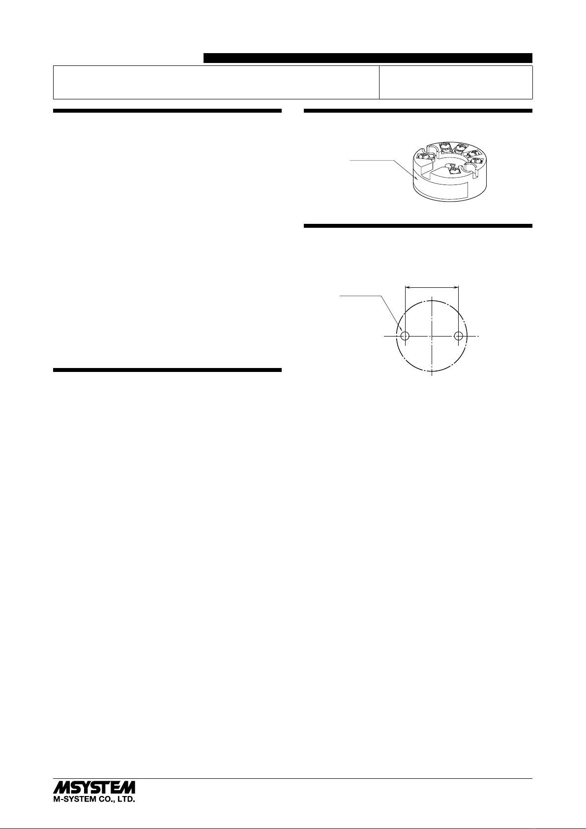
COMPONENT IDENTIFICATION
Specifications
INSTALLATION unit : mm (inch)
This module is suitable for mounting inside a DIN type B
head.
33 (1.30)
2–M4 SCREW
The screws are to be provided by the customer.
27U
5-2-55, Minamitsumori, Nishinari-ku, Osaka 557-0063 JAPAN
Phone: +81(6)6659-8201 Fax: +81(6)6659-8510 E-mail: info@m-system.co.jp
EM-7656-A Rev.3 P. 2 / 2
TERMINAL CONNECTIONS
Connect the module as in the diagram below.
■EXTERNAL DIMENSIONS unit : mm (inch)
44 (1.73) dia.
6.3
(.25)
33 (1.30) 6 (.24) dia.
16.5 (.65)
6–M3 SCREW
2–4.5 (.18) dia.
MTG HOLE
20.7 (.81)
19.5 (.77)
12.7 (.5)
14
32
–+
7.6 (.30) dia.
■CONNECTION DIAGRAM
4
2
3
1
+
–
LOAD
OUTPUT
24V DC
4 – 20mA DC
*2
INPUT *1
*1. Input Connection Examples
4
2
3
1
■ DC MILLIVOLT
+
–
INPUT
4
2
3
1
■ THERMOCOUPLE
• Single input
+
–
–
+
comp. leadwire
4
2
3
1
■ RTD & RESISTANCE
• Two-wire
4
2
3
1
• Three-wire
4
2
3
1
• Dual input
+
+
–
+
–
comp. leadwire
+–
B
B
A
B
A
4
2
3
1
• Four-wire
B
B
A
A
SENSOR 2
SENSOR 1
*2. Limited to 250 – 500Ω when using the communication
to configure the module.
WIRING INSTRUCTIONS
■SCREW TERMINAL
Torque: 0.5 N·m
CHECKING
1) Terminal wiring: Check that all cables are correctly con-
nected according to the connection diagram.
2) Input: Check that the input signal is within 0 – 100% of
full-scale.
If the thermocouple / RTD or its extension wires are bro-
ken, the output goes over 100% (below 0% with down-
scale) due to the burnout function. Check leadwires in
such a case.
3) Output: Check that the load is within the permissible
limit including wiring resistance.
Load Resistance (Ω) = Supply Voltage (V) – 9 (V)
0.023 (A)
(including leadwire resistance)
ADJUSTMENT PROCEDURE
To calibrate the signal to match with a receiving instru-
ment or to change the factory-set configurations, use the PC
Configurator software installed on a Windows PC via the
Bell202 Modem (model COP-HU).
The PC Configurator software is downloadable at M-Sys-
tem’s web site: http://www.m-system.co.jp
LIGHTNING SURGE PROTECTION
M-System offers a series of lightning surge protector for
protection against induced lightning surges. Please contact
M-System to choose appropriate models.

Other M-system Transmitter manuals

M-system M5CT User manual

M-system

M-system M5CT User manual

M-system W2RS User manual

M-system

M-system W2RS User manual

M-system 10JM User manual

M-system

M-system 10JM User manual

M-system 10PA User manual

M-system

M-system 10PA User manual

M-system M3LLC User manual

M-system

M-system M3LLC User manual

M-system Mini-M M2UDS2 User manual

M-system

M-system Mini-M M2UDS2 User manual

M-system 27PM User manual

M-system

M-system 27PM User manual

M-system M2EXV User manual

M-system

M-system M2EXV User manual

M-system Mini-M M2REB User manual

M-system

M-system Mini-M M2REB User manual

M-system Mini-M M2XM2 User manual

M-system

M-system Mini-M M2XM2 User manual

M-system W2VABS User manual

M-system

M-system W2VABS User manual

M-system M3LR User manual

M-system

M-system M3LR User manual

M-system M5XREB User manual

M-system

M-system M5XREB User manual

M-system 18KJV User manual

M-system

M-system 18KJV User manual

M-system CTH User manual

M-system

M-system CTH User manual

M-system W2CFG User manual

M-system

M-system W2CFG User manual

M-system Mini-M M2PA User manual

M-system

M-system Mini-M M2PA User manual

M-system Mini-M M2CEC User manual

M-system

M-system Mini-M M2CEC User manual

M-system M3SXR User manual

M-system

M-system M3SXR User manual

M-system M5PA-CA-R User manual

M-system

M-system M5PA-CA-R User manual

M-system 10JRE User manual

M-system

M-system 10JRE User manual

M-system M3SMS User manual

M-system

M-system M3SMS User manual

M-system W2PA User manual

M-system

M-system W2PA User manual

M-system CTS2 User manual

M-system

M-system CTS2 User manual

Popular Transmitter manuals by other brands

Knick Stratos Multi E461N user manual

Knick

Knick Stratos Multi E461N user manual

CYP Dante AU-DTI4-TX Operation manual

CYP

CYP Dante AU-DTI4-TX Operation manual

Becker Centronic TimeControl TC4410-II Assembly and operating instructions

Becker

Becker Centronic TimeControl TC4410-II Assembly and operating instructions

EUTECH INSTRUMENTS ALPHA PH 1000 PHORP CONTROLLERTRANSMITTER instruction manual

EUTECH INSTRUMENTS

EUTECH INSTRUMENTS ALPHA PH 1000 PHORP CONTROLLERTRANSMITTER instruction manual

Zaxcom ZMT-421 user manual

Zaxcom

Zaxcom ZMT-421 user manual

Widex SCOLA User instructions

Widex

Widex SCOLA User instructions

ATEN VE2812UST user manual

ATEN

ATEN VE2812UST user manual

THORLABS MX10C user guide

THORLABS

THORLABS MX10C user guide

THUNDER TIGER 2ADKO-A-8-200 user manual

THUNDER TIGER

THUNDER TIGER 2ADKO-A-8-200 user manual

ARG ARG-900AT Manual and user guide

ARG

ARG ARG-900AT Manual and user guide

SGM LEKTRA RPL81 manual

SGM LEKTRA

SGM LEKTRA RPL81 manual

Sennheiser SK 2000 manual

Sennheiser

Sennheiser SK 2000 manual

Genie 110745 instructions

Genie

Genie 110745 instructions

Festo SDAT-MHS-SV Series operating instructions

Festo

Festo SDAT-MHS-SV Series operating instructions

Dakota Alert BBT-2500 user guide

Dakota Alert

Dakota Alert BBT-2500 user guide

JUMO CTI-750 operating instructions

JUMO

JUMO CTI-750 operating instructions

Pfeiffer Vacuum RPT 100 operating instructions

Pfeiffer Vacuum

Pfeiffer Vacuum RPT 100 operating instructions

Inovonics EE1216 Installation instructions manual

Inovonics

Inovonics EE1216 Installation instructions manual

manuals.online logo
manuals.online logoBrands
  • About & Mission
  • Contact us
  • Privacy Policy
  • Terms and Conditions

Copyright 2025 Manuals.Online. All Rights Reserved.