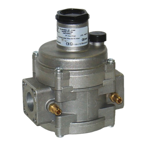
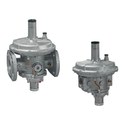
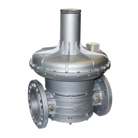
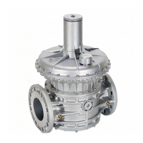
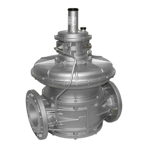
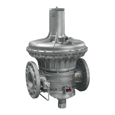
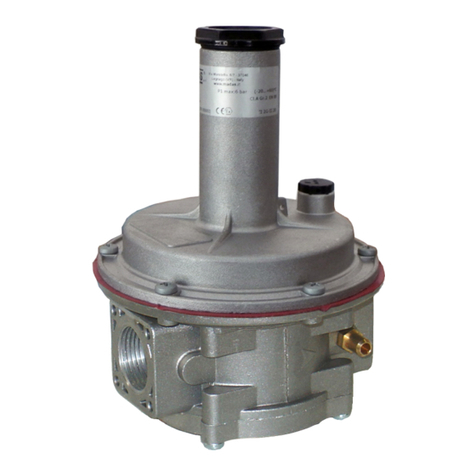
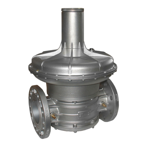
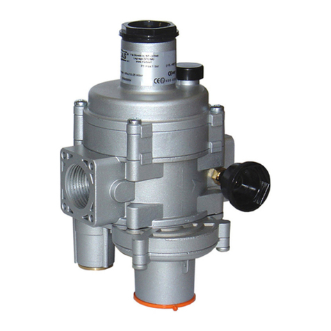
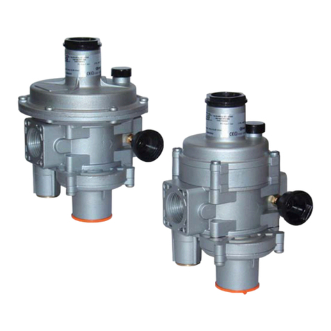
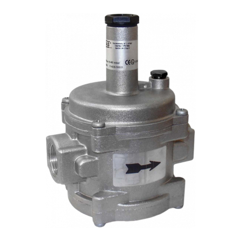
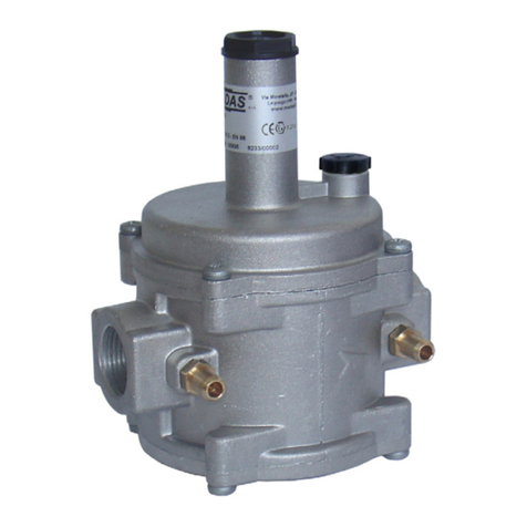
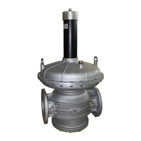
Madas RG/2MCS User manual

RG/2MBZ
RG/2MCS
MADE IN ITALY
II 2G - II 2D
0497
REGOLATORE DI PRESSIONE PER GAS
GAS PRESSURE REGULATOR
REGULATEUR DE PRESSION POUR GAZ
REGULADOR DE PRESIÓN PARA GAS
RG/2MCS - RG/2MBZ
CHAPTER
5.2a
SEC TION
5
Madas Technical Manual - 5|5.2a - REV. 0 of th Apr 2019 - RG/2MCS - RG/2MBZ
IT EN FR ES
Range pressione di esercizio
Operating pressure range
Plage de pression de fonctionnement
Rango de la presión de funcionamiento
Pe: 0,5÷5 bar
Attacchi filettati / Threaded connections
Raccords filetés / Conexiones roscadas
DN 32 - DN 40 - DN 50
Attacchi flangiati/ Flanged connections
Raccords à brides / Conexiones embridadas
DN 32 - DN 40 - DN 50
Norma di riferimento / Reference standard
Norme de référence / Patrón de referencia EN 88-2
In conformità a *
In conformity with *
Conforme a *
Conforme *
Direttiva PED
2014/68/UE
PED Directive
2014/68/EU
Directive PED
2014/68/UE
Directiva PED
2014/68/UE

ES FR EN IT
2Madas Technical Manual - 5|5.2a - REV. 0 of th Apr 2019RG/2MCS - RG/2MBZ
INDICE INDEX INDEX ÍNDICE
pag.
Italiano ........................................................................................................................................................3
English ........................................................................................................................................................12
Français ......................................................................................................................................................21
Español .......................................................................................................................................................30
Portate regolatori (tabella 1)................................................................................................................................39
Capacities of regulators (table 1) .....................................................................................................................
Débit des régulateurs (tableau 1).....................................................................................................................
Caudal de los reguladores (tabla 1)..................................................................................................................
Disegni - Drawings - Dessins - Diseños ............................................................................................................40
Caratteristiche molle di regolazione (tabella 2) ....................................................................................................44
Regulation spring data (table 2) .......................................................................................................................
Caracteristiques des ressorts de reglage (tableau 2) ...........................................................................................
Características muelles de regulación (tabla 2) ...................................................................................................
Codifica prodotto / Product encoding / Codification du produit / Codificación del producto.......................................45
Dimensioni (tabella 5) ...................................................................................................................................51
Dimensions (table 5) .....................................................................................................................................
Dimensions (tableau 5) ..................................................................................................................................
Dimensiones (tabla 5) ..................................................................................................................................

ES FR EN IT
12 Madas Technical Manual - 5|5.2a - REV. 0 of th Apr 2019RG/2MCS - RG/2MBZ
1.0 GENERAL INFORMATION
This manual shows you how to safely install, operate and use the device.
The instructions for use ALWAYS need to be available in the facility where the device is installed.
ATTENTION: installation/maintenance needs to be carried out by qualified staff (as explained in
section 1.3) by using suitable personal protective equipment (PPE).
For any information pertaining to installation/maintenance or in case of problems that cannot be solved with the instructions,
contact the manufacturer at the address and phone numbers provided on the last page.
1.1 DESCRIPTION
Device which supplies a preset and constant “downstream” pressure value (Pa) (within the intended operating limits) according
to variations in the inlet pressure (Pe) and/or the flow rate (Q). The compensated obturator ensures precision when adjusting
the outlet pressure (Pa) even with high and sudden variations in the inlet pressure.
These regulators are used in both civil and industrial installations where natural gas, LPG or other non-corrosive gases (dry
gases) are used.
Reference standards: EN 88-2 – EN 13611.
They can be equipped with the following safety devices and accessories according to the system requirements:
• downstream overpressure shut off device (OPSO): stops supply when the regulator outlet pressure exceeds
the setting value of the device. The OPSO device is always present on these devices.
• downstream minimum pressure shut off device (UPSO): stops supply when the regulator outlet pressure
drops below the setting value of the device. It also intervenes in the event of an upstream power failure. They can also be
supplied without the UPSO device.
• relief valve: discharges small gas flows outwards if overpressure occurs downstream of the regulator. This discharge
can be conveyed outwards if the installation is in a poorly ventilated environment. They can also be supplied without the
relief valve.
• outlet pressure socket.
1.2 KEY TO SYMBOLS
ATTENTION: Attention
is drawn to the technical
details intended for
qualified staff.
DANGER: In the event of
inobservance, this may cause
damage to tangible goods, to people
and/or pets
.
DANGER: In the event
of inobservance, this may
cause damage to tangible
goods.
1.3 QUALIFIED STAFF
These are people who:
•Are familiar with product installation, assembly, start-up and maintenance;
•Know the regulations in force in the region or country pertaining to installation and safety;
•Have first-aid training.
1.4 USING NONORIGINAL SPARE PARTS
•To perform maintenance or replace spare parts (e.g. spring, filter element, etc.) ONLY manufacturer-recommended parts
can be used. Using different parts not only voids the product warranty, it could compromise correct device operation.
•The manufacturer is not liable for malfunctions caused by unauthorised tampering or use of non-original spare parts.
1.5 IMPROPER USE
•The product must only be used for the purpose it was built for.
•It is not allowed to use fluids other than those expressly stated.
•The technical data provided on the rating plate must not, under any circumstances, be exceeded. The end user or installer is in
charge of implementing correct systems to protect the device, which prevent the maximum pressure indicated on the rating plate
from being exceeded.
•The manufacturer is not responsible for any damage caused by improper use of the device.

IT EN FR ES
13
Madas Technical Manual - 5|5.2a - REV. 0 of th Apr 2019 RG/2MCS - RG/2MBZ
2.0 TECHNICAL DATA
• Use : non-aggressive gases of the three families (dry gases)
• Ambient temperature (TS) : -20 ÷ +60°C
• Minimum operating pressure : 0.5 bar
• Max operating pressure : 5 bar
• Allowable pressure PS : 5 bar
• Safety lock closing time : < 1 s
• Accuracy class : AC=10 - (Pa ± 10%)
• Overpressure shut off accuracy unit : AG=10
• Closing pressure class : SG=30
• Relief valve : tested according to the indications in EN 334
• Connecting the vent : G 3/8
• Mechanical strength : Group 2 (according to EN 13611)
• Rp threaded connections : (DN 32 - DN 40 - DN 50) according to EN 10226
• Flanged connections that can couple with PN 16 flanges : (DN 32 - DN 40 - DN 50) ISO 7005 / EN 1092-1
• NPT threaded or ANSI 150 flanged connections : on request
• In compliance with : PED Directive 2014/68/EU - ATEX Directive 2014/34/EU
2.1 MODEL IDENTIFICATION (for configurations see page 45 - 50)
RG/2MCS: Pressure regulator - without safety shut-offs
RG/2MBZ: Pressure regulator - with safety shut-offs
3.0 COMMISSIONING THE DEVICE
3.1 OPERATIONS PRIOR TO INSTALLATION
•It is necessary to close the gas upstream of the device prior to installation;
•Make sure that the line pressure DOES NOT EXCEED the maximum pressure declared on the product label;
•Protective caps (if any) must be removed prior to installation;
•The pipes and inside of the device must be clear of any foreign bodies;
•IMPORTANT:
•to avoid possible pumping and/or disturbances in the gas flow, a straight pipe section equal to at least 5 DN must be
installed (downstream of the regulator);
•install manual gas closing devices (e.g. ball valves) upstream and downstream of the regulator to protect it from any
pipe leak test;
•do consider that if the regulator is equipped with a relief valve, the latter is suitable for small quantities of gas to be
discharged and CANNOT replace the relief valve installed separately as a specific device;

ES FR EN IT
14 Madas Technical Manual - 5|5.2a - REV. 0 of th Apr 2019RG/2MCS - RG/2MBZ
If the device is threaded:
make sure that the pipe thread is not too long, to prevent damaging the body of the device when screwing it on;
If the device is flanged:
•make sure the inlet and outlet counter-flanges are perfectly coaxial and parallel in order to prevent unnecessary
mechanical stress to the body. Also calculate the space to insert the seal gasket;
•With regard to tightening operations, equip yourself with one or two calibrated torque wrenches or other controlled locking
tools;
•With outdoor installation, it is advisable to install a protective roof to prevent rain from oxidising or damaging parts of the
device.
•According to the plant geometry, check the risk of an explosive mixture arising inside the piping;
•If the regulator is installed near other devices or as part of an assembly, compatibility between the regulator and
these devices must be evaluated beforehand;
•Provide protection against impact or accidental contact if the device is accessible to unqualified personnel.
3.2 INSTALLATION (see examples in 3.4)
Threaded devices:
•Assemble the device by screwing it, with the due seals, onto the plant with pipes and/or fittings whose threads are consistent
with the connection being attached;
•Do not use the neck of the top cover (25) as a lever to help you screw it on, but only use the specific tool;
•The arrow, shown on the body (20) of the device, needs to be pointing towards the application;
Flanged devices:
•Assemble the device by flanging it, with the due seals, onto the plant with pipes whose flanges are consistent with the
connection being attached. The gaskets must be free from defects and must be centred between the flanges;
•If, after installing the gaskets, there is still an excessive space in between, do not try to reduce the
said gap by excessively tightening the bolts of the device;
•The arrow, shown on the body (20) of the device, needs to be pointing towards the application;
•Insert the relative washers inside the bolts in order to prevent damage to the flanges during
tightening;
•When tightening, be careful not to “pinch” or damage the gasket;
•Tighten the nuts or bolts gradually, in a “cross” pattern
(see the example alongside);
•Tighten them, first by 30%, then by 60% and finally 100% of the maximum
torque (see the example alongside, according to EN 13611);
• Tighten each nut and bolt again clockwise at least once, until the maximum torque has been achieved uniformly;
Common procedures (threaded and flanged devices):
•The regulator is normally positioned before the application. Previously evaluate the possibility of installing the regulator as
shown in the installation example in 3.4;
•It can be installed in any position even if the installation shown in 3.4 (installation examples) is preferred. A pressure outlet (19)
can be found outside the regulator, downstream from it, to control the regulation pressure (Pa);
•It is necessary to connect the pulse outlet with a G 1/4 fitting downstream of the regulator (see installation examples). To
do so, remove the cap (21);
• Drain the relief valve (if any) outwards (as shown in 3.4) by removing the dust cap (24);
•It is always recommended to install a compensation joint;
•During installation, avoid debris or metal residues from getting into the device;
•To guarantee mechanical tension-free assembly, we recommend using compensating joints, which also adjust to the pipe’s
thermal expansion;
•If the device is to be installed in a ramp, it is the installer’s responsibility to provide suitable supports or correctly sized
supports, to properly hold and secure the assembly. Never, for any reason whatsoever, leave the weight of the ramp only on
the connections (threaded or flanged) of the individual devices;
•In any case, after installation check the tightness of the system, without subjecting the diaphragm of the regulator (therefore,
the downstream pipe section) to a pressure higher than 300 mbar (valid only for versions with standard working diaphragm).
For versions with reinforced diaphragm, check the tightness with a pressure equal to 1.5 times the regulator setting pressure.
Diameter DN 32 DN 40 DN 50
Max. torque (N.m) 50 50 50
IT EN FR ES
15
Madas Technical Manual - 5|5.2a - REV. 0 of th Apr 2019 RG/2MCS - RG/2MBZ
3.4 GENERAL EXAMPLES OF INSTALLATION
EXAMPLE 1 (RG/2MCS)
1. Expansion joint/anti-vibration mount
2. Upstream ball valve
3. FM gas filter
4. OPSO series MVB/1 MAX shut off valve
5. RG/2MCS pressure regulator
3.3 INSTALLATION IN PLACES WHERE THERE IS THE RISK OF EXPLOSION (DIRECTIVE 2014/34/EU)
The regulator complies with Directive 2014/34/EU (formerly 94/9/EC) as group II equipment, category 2G and as group II
equipment, category 2D; consequently, it is suited for installation in zones 1 and 21 (in addition to zones 2 and 22) as classified
in Annex I of Directive 99/92/EC. The regulator is not suited for use in zones 0 and 20 as defined in the aforementioned Directive
99/92/EC. To determine the qualification and size of the danger zones, please refer to standard IEC EN 60079-10-1.
If installed and subject to maintenance in full compliance with all conditions and technical instructions provided in this manual,
the device does not pose a source of specific hazards: in particular, under conditions of normal operation, the regulator is
expected to emit a flammable substance into the atmosphere only occasionally, and specifically:
The regulator can be dangerous with respect to the presence of other devices nearby if the integrated relief valve is triggered
or if the working diaphragm (22) or the blocking diaphragm (27) fails. If the diaphragm fails, the regulator becomes a source
of explosive atmosphere emission of continuous degree and, as such, it can generate hazardous areas 0 as defined in Directive
99/92/EC.
In particularly critical installation conditions (unattended areas, poor maintenance or poor ventilation) and especially if there are
potential sources of ignition and/or hazardous equipment near the regulator in regular operation, as they may generate electric
arcs or sparks, a preliminary assessment of the compatibility between the regulator and such equipment must be carried out.
In any case, every useful precaution must be adopted so as to prevent the regulator from generating zones 0: for example,
annually verify regular operation, possibility of changing the degree of emission of the source or intervening on the explosive
substance discharge by directing it outwards. To do so, simply remove the dust caps (12) and (24) by connecting the specific
pipe (respectively, G 3/8 and G 1/8) conveyed to the outside (see installation examples in 3.4).
piping
applicaon
discharge in
open air
12
3
6
5
7
8
9
10
4
internal thermal unit
non-hazardous venlated zone*
external roof
* if the zone is ATEX classified follow the indications of 3.3
6. Ball valve downstream of the regulator
7. Vent valve
8. MVS/1 relief valve
9. Low pressure gauge and relative button
10. High pressure gauge and relative button
Ø ext. min 8mm
Ø int. min 6mm
5 DN

ES FR EN IT
16 Madas Technical Manual - 5|5.2a - REV. 0 of th Apr 2019RG/2MCS - RG/2MBZ
piping
applicaon
discharge in open air
12
3
6
5
7
8
4
internal thermal unit
non-hazardous venlated zone*
external roof
EXAMPLE 2 (RG/2MBZ)
1. Expansion joint/anti-vibration mount
2. Upstream ball valve
3. RG/2MBZ pressure regulator
4. Ball valve downstream of the regulator
* if the zone is ATEX classified follow the indications of 3.3
4.0 MANUAL RESET
•Make sure that all valves and downstream taps are closed;
•Unscrew the cap (11 );
•Lightly press the reset pin (29), wait a few moments for the pressure to balance and then fully press the reset pin (29);
•Hold down the reset pin (29), slowly open the valve downstream of the regulator;
•Release the reset pin (29);
•Then tighten the cap (11 ) back in the initial position.
5.0 FIRST STARTUP
Before commissioning, verify that:
•all of the instructions on the rating plate, including the direction of flow, are observed;
•the holes of the dust caps (12) and (24) are not clogged (regulator and shut off);
•IMPORTANT: The leak test of the piping must be performed without subjecting the diaphragm of the regulator
(therefore, the downstream pipe section) to a pressure higher than 300 mbar (for reinforced diaphragm 1.5 times
the regulator setting pressure). Use special manual gas closing devices to avoid damaging the regulator;
•The pressurisation manoeuvre of the equipment must be carried out very slowly so as to avoid possible damage.
NOTE: under no circumstances should a blind cap be installed in place of dust caps (12) and (24) as the
regulator and/or the safety shut offs may not work;
•Close the ball valve downstream of the regulator and partially open the downstream relief valve;
•Slowly open the upstream shut-off devices;
•Close the vent valve;
•Proceed by manually resetting the regulator (see 4.0);
•Close the downstream valve so as to close the regulator (the Pa value increases the SG value to fully close the obturator);
•Check the tightness of the system seals and check the internal/external tightness of the regulator, of the relief valve and of
the external sensor tube, if applicable;
•Slowly open the downstream valve and the shut-off valve;
•Check the operation of the regulator.
5. Vent valve
6. MVS/1 relief valve
7. Low pressure gauge and relative button
8. High pressure gauge and relative button
Ø ext. min 8mm
Ø int. min 6mm
5 DN

IT EN FR ES
17
Madas Technical Manual - 5|5.2a - REV. 0 of th Apr 2019 RG/2MCS - RG/2MBZ
6.0 SETTING
Before carrying out the operations, make sure that the supplied spring/s is/are suitable for the desired Pa - OPSO - UPSO and
differential relief valve fields.
6.1 - Adjusting the maximum pressure shut off (OPSO)
•Unscrew the cap (11 );
•Use the supplied key (32) to fully tighten the adjustment ring nut of the maximum shut off (28);
•Start the system, reset the shut off device as indicated in 4.0 and make sure that there is no gas consumption (close the
applications downstream of the regulator);
Method 1:
1. Loosen and remove caps (26) and (11 );
2. Use an 8 mm socket wrench (see fig. 1a and 2a) to press on the nut (4), slowly increasing the downstream pressure
to the desired value and simultaneously keep the nut (4) pressed; use the key supplied (32) to loosen the ring nut
(28) until the device is triggered;
3. Tighten the caps back to their original position and repeat the Pa setting steps;
Method 2:
1. Alternatively, use an auxiliary gas pressure to slowly increase the downstream pressure to the desired value and
simultaneously, use the key supplied (32) to loosen the ring nut (28) until the device is triggered (so as to avoid
having to set the Pa again);
•In both cases, reset the system by following the correct procedure and verify that the trigger value is that desired by repeating
the release step 2-3 times;
•If necessary, adjust the trigger value by turning the ring nut (28) with the specific key (32).
6.2 - Adjusting the minimum pressure shut off (UPSO)
•Unscrew the cap (11 );
•Use the key supplied (32) to loosen the adjustment ring nut of the minimum shut off (30) to the minimum;
•Start the system and reset the shut off device as described in 4.0;
•Reduce the downstream pressure to the desired trigger value;
•Use the key supplied (32) to tighten the adjustment ring nut (30) until the minimum pressure shut off is triggered.
•Reset the system by following the correct procedure and verify that the trigger value is that desired by repeating the release
step 2-3 times;
•If necessary, adjust the trigger value by turning the ring nut (30) with the specific key (32);
6.3 - Adjusting the relief valve (differential DfRv)
NOTE: The relief valve (if any) in these regulators is differential, therefore the range value (DfRv) indicated must be added to
the range value of the outlet pressure (Pa).
Example: Pa=32-60 mbar - DfRv=15-40 mbar.
Means that the relief valve can be calibrated from: (Pa min + DfRv min) = 32+15=47 mbar to: (Pa max + DfRv max) =
60+40=100 mbar
Therefore the effective range of the relief valve (in this case) is 47-100 mbar.
•Start the system and set the shut off as described in point 4.0;
•Slowly close the valve downstream of the regulator;
•Loosen and remove the cap (26);
•Use the 8 mm socket spanner (see fig. 1 and 2) to fully tighten the nut (4);
•Use the 8 mm socket spanner to press the adjustment nut (4) and increase the pressure Pa, reading it on the pressure gauge,
up to the desired setting value;
•Without pressing further, slowly loosen the adjustment nut (4) until the pressure Pa begins to decrease, shown on the
pressure gauge;
•In this case, the relief valve is set to the desired value;
•Remove the socket spanner and close the cap (26).

ES FR EN IT
18 Madas Technical Manual - 5|5.2a - REV. 0 of th Apr 2019RG/2MCS - RG/2MBZ
6.4 - Adjusting the outlet pressure (Pa)
The outlet pressure Pa (unless specifically requested) is factory-set with the regulator installed as indicated in 3.4 and with
the adjustment screw (1) set approximately at the minimum setting value. The safety shut offs/relief valve are set accordingly;
If the regulator is installed in different positions, check and reset the outlet pressure Pa, and consequently the devices
incorporated in the regulator;
Adjust the outlet pressure as follows:
•Unscrew the cap (26);
•Unscrew the adjustment screw (1) and set it to the minimum setting allowed (threaded end of the top cover (25))
;
•Start the system or make sure there is a minimum flow downstream of the regulator;
•To increase the pressure calibration downstream of the regulator, tighten the adjustment screw (1) to the desired value.
Perform the reading with a calibrated pressure gauge, installed downstream of the regulator to at least 5 DN (see examples
in 3.4);
•Screw the cap (26) back on and if necessary, seal it in that position using the appropriate seal holes (if any);
•Use pressure outlets (19)on the device only for zero flow or very low flow measurements.
7.0 - RECOMMENDED PERIODIC CHECKS
•Use a suitable calibrated tool to ensure that the bolts are tightened as indicated in 3.2;
•Check the tightness of the flanged/threaded connections on the system;
•Check the tightness and operation of the regulator/shut off/relief valve;
The final user or installer is responsible for defining the frequency of these checks based on the severity of the service conditions.
7.1 - CHECK THAT THE MAXIMUM PRESSURE SHUT OFF VALVE IS WORKING (OPSO)
Reset the shut off device and close the valve downstream of the regulator;
Method 1:
1. Loosen and remove caps (26) and (11 );
2. Use the same tool (shown in fig. 1 and 2) to press the nut (4) and slowly increase the downstream pressure until the
device is triggered;
3. Tighten the caps back to their original position and repeat the Pa setting steps (6.4);
Method 2:
1. Alternatively, use an auxiliary gas pressure to slowly increase the downstream pressure until the device is triggered
(so as to avoid having to set the Pa again).
7.2 - CHECK THAT THE MINIMUM PRESSURE SHUT OFF VALVE IS WORKING (UPSO)
•Reset the shut off device and close the ball valve upstream of the regulator;
•open the relief valve, downstream of the device, partially and slowly. As the outlet pressure decreases slowly it will cause the
minimum shut off to trigger at its setting value;
•Repeat the trigger step 2-3 times to make sure that the system functions correctly. Between one trigger and another, set the
downstream pressure back to the setting value.
7.3 - CHECK THE TIGHTNESS OF THE DEVICES (OPSO AND UPSO)
•Fully empty the downstream pipe section (wait a few seconds to allow it to empty completely). The downstream pressure
must remain at zero when the relief valve is closed.

IT EN FR ES
19
Madas Technical Manual - 5|5.2a - REV. 0 of th Apr 2019 RG/2MCS - RG/2MBZ
7.4 - CHECK THAT THE RELIEF VALVE IS WORKING PROPERLY
•Start the system and set the shut off as described in point 4.0;
•Slowly close the valve downstream of the regulator;
•Loosen and remove the cap (26);
•Use an 8 mm socket spanner to press the adjustment nut (4) to increase the pressure Pa above the preset value, while
preventing the OPSO shut off from being triggered. Use a calibrated pressure gauge for the reading;
•Remove the socket spanner. The generated overpressure will be discharged outwards and the Pa will begin to decrease to
the relief valve setting value. Relief valve operation is verified;
•Close the cap (26);
•Open the relief valve to discharge the created overpressure;
•Close the relief valve (the regulator goes to the closing pressure) and open the ball valve downstream of the regulator.
8.0 MAINTENANCE
•No maintenance operations need to be carried out inside the device. If operations must be carried out inside the
device (changing the spring, replacing the filter, etc.), it is advisable to contact the Technical Department. In any
case, before carrying out any dismantling operation on the device, make sure that there is no pressurised gas inside.
9.0 TRANSPORT, STORAGE AND DISPOSAL
• During transport the material needs to be handled with care, avoiding any impact or vibrations to the device;
• If the product has any surface treatments (ex. painting, cataphoresis, etc) it must not be damaged during transport;
• The transport and storage temperatures must observe the values provided on the rating plate;
• If the device is not installed immediately after delivery it must be correctly placed in storage in a dry and clean place;
• In humid facilities, it is necessary to use driers or heating to avoid condensation;
• At the end of its service life, the product must be disposed of in compliance with the legislation in force in the country where
this operation is performed.
10.0 WARRANTY
The warranty conditions agreed with the manufacturer at the time of the supply apply.
Damage caused by:
• Improper use of the device;
• Failure to observe the requirements described in this document;
• Failure to observe the regulations pertaining to installation;
• Tampering, modification and use of non-original spare parts;
are not covered by the rights of the warranty or compensation for damage.
The warranty also excludes maintenance work, the assembly of parts or non-original spare parts, making changes to the
device and natural wear.

ES FR EN IT
20 Madas Technical Manual - 5|5.2a - REV. 0 of th Apr 2019RG/2MCS - RG/2MBZ
11.0 RATING PLATE DATA
The rating plate data (see examples above) includes the following:
• Manufacturer’s name/logo and address (possible distributor name/logo)
• Mod.: = name/model of the device followed by the connection diameter
• PS =
Allowable pressure
• Pe =
Maximum pressure or inlet pressure range that product operation is guaranteed at
• TS = Temperature range within which product operation is guaranteed
• Pa = Outlet pressure range
• Wdso = OPSO calibration range that can be achieved with the spring provided (without replacing any part)
• AC = Accuracy class Pa
• SG = Closing pressure class
• AG =
Overpressure block accuracy unit
• EN 88-2 = Product reference regulation
• Wdsu = UPSO calibration range that can be achieved with the spring provided (without replacing any part)
• DfRv = Differential relief valve range with respect to Pa
• year = Year of manufacture
• Lot = Product serial number (see explanation below)
• U1823 = Lot issued in year 2018 in the 23rd week
• 14216 = progressive job order number for the indicated year
• 00001 = progressive number referring to the quantity of the lot
• = In compliance with ATEX Dir. followed by the protection mode
• = In compliance with PED directive followed by the no. of the Notified Body
RG/2MCS
RG/2MBZ
Mod.: RG/2MCS DN 50 PS=Pe:0,5-5 bar TS: -20+60°C
Pa: 32-60 mbar DfRv:15-40 mbar AC10 SG30 EN 88-2
year: 2018 Lot:U1823 14216/00001
Via Moratello, 5/7 - 37045
Legnago (VR) - Italy
www.madas.it
0497
II2G
II2D
Mod.: RG/2MBZ DN 50 PS=Pe:0,5-5 bar TS: -20+60°C
Pa: 32-60 mbar Wdso:70-140 mbar AC10 SG30 AG10 EN 88-2
Wdsu:10-30 mbar DfRv:15-40 mbar
year: 2018 Lot:U1823 14216/00001
Via Moratello, 5/7 - 37045
Legnago (VR) - Italy
www.madas.it
0497
II2G
II2D

IT EN FR ES
39
Madas Technical Manual - 5|5.2a - REV. 0 of th Apr 2019 RG/2MCS - RG/2MBZ
Tabella 1 - Table 1 - Tableau 1 - Tabla 1
PORTATE REGOLATORI / CAPACITIES OF REGULATORS / DÉBIT DES RÉGULATEURS / CAUDAL DE LOS REGULADORES
(Nm3/h) Gas naturale - Natural Gas - Gaz naturel - Gas natural
Modello
Model
Modèle
Modelo
Pa
(mbar)
Pressione di ingresso - Inlet Pressure - Pression d'entrée - Presión de entrada
0,5 bar 1 bar 2 bar 3 bar 4 bar 5 bar
DN 32
20 270 430 450 450 450 450
30 270 430 510 510 510 510
50 270 410 600 620 620 620
100 250 400 650 740 740 740
200 190 320 550 740 860 860
300 190 370 650 890 940 940
400 110 270 700 930 1100 1100
600 - 260 680 970 1200 1200
800 - 230 620 960 1260 1300
DN 40
20 270 430 690 700 700 700
30 270 430 690 700 700 700
50 270 430 700 860 870 890
100 260 420 690 950 1050 1070
200 200 340 600 850 1020 1170
300 190 380 670 940 1160 1380
400 115 270 740 970 1260 1500
600 - 260 680 970 1280 1500
800 - 240 620 960 1260 1500
DN 50
20 300 460 750 990 1290 1500
30 300 460 750 1000 1300 1500
50 300 460 750 1000 1300 1500
100 280 450 740 1000 1300 1500
200 220 370 660 930 1160 1410
300 210 390 700 960 1250 1500
400 124 320 620 960 1270 1600
600 - 290 680 1000 1300 1580
800 - 240 650 990 1280 1570
DN 50
tubo uscita DN 80
outlet DN 80 pipe
tube aval DN 80
tubería de aguas
abajo DN 80
20 300 470 760 1000 1300 1500
30 300 470 760 1000 1300 1500
50 300 470 760 1000 1300 1500
100 280 460 750 1010 1300 1500
200 240 410 710 970 1100 1410
300 220 420 730 990 1300 1500
400 146 360 630 1020 1310 1600
600 - 315 690 1020 1310 1600
800 - 240 650 990 1280 1570
* Dati ricavati CON L’UTILIZZO del tubetto sensore esterno.
* Data obtained USING the external sensor tube.
* Données obtenues AVEC L’UTILISATION du tube capteur extérieur.
* Datos obtenidos USANDO el tubo sensor externo.
Aria - Air - Air - Aire = 0,806
Gas naturale - Natural Gas - Gaz naturel - Gas natural = 1
Gas di città - Town gas - Gaz de ville - Gas de ciudad = 1.177
GPL - LPG - Gaz de pétrole liquéfié - Gas líquido = 0.62

ES FR EN IT
40 Madas Technical Manual - 5|5.2a - REV. 0 of th Apr 2019RG/2MCS - RG/2MBZ
fig. 1 - RG/2MCS
RG/2MCS RG/2MBZ
Utensile necessario per taratura Pa / Required tool for setting Pa
Outil nécessaire pour régler Pa / Herramienta requerida para calibración de Pa
Pa Range
(mbar)
con sfioro / with relief
avec évacuation / con alivio
senza sfioro / without relief
sans évacuation / sin alivio
10 ÷ 22
13mm
17 ÷ 32
32 ÷ 60
50 ÷ 95
85 ÷ 180
150 ÷ 350*
13mm
300 ÷ 500*
500 ÷ 800*
* = versioni con membrana rinforzata = versions with reinforced diaphragm
* = versions avec membrane renforcée = versiones con membrana reforzada
G 3/8
G 1/4

IT EN FR ES
41
Madas Technical Manual - 5|5.2a - REV. 0 of th Apr 2019 RG/2MCS - RG/2MBZ
fig. 2 - RG/2MBZ
Versione con sfioro / Version with relief valve
Version avec évacuation / Versión con alivio
G 3/8
G 1/4
8mm
Per taratura sfioro
For relief valve setting
Pour étalonnage évacuation
Para calibración alivio
Per taratura OPSO
For OPSO setting
Pour étalonnage OPSO
Para calibración OPSO
Per taratura UPSO
For UPSO setting
Pour étalonnage UPSO
Para calibración UPSO

ES FR EN IT
42 Madas Technical Manual - 5|5.2a - REV. 0 of th Apr 2019RG/2MCS - RG/2MBZ
EN
fig. 1 e 2
1. Regolazione pressione di uscita (Pa)
2. Rondella per molla
3. Molla di taratura Pa
4. Regolazione sfioro
5. Disco superiore per membrana
6. Viti di fissaggio coperchio superiore
7. Flangia
8. Membrana di compensazione
9. Fondello
10. Molla di taratura OPSO
11. Tappo di chiusura inferiore
12. Tappo antipolvere G 1/8
13. Otturatore (regolatore)
14. Perno centrale (regolatore)
15. O-Ring di tenuta coperchio inferiore
16. Viti di fissaggio coperchio inferiore
17. Otturatore (blocco di sicurezza)
18. Tubo sensore interno
19. Presa di pressione (optional)
20. Corpo
21. Tappo G 1/4 per presa impulso esterna
22. Membrana di funzionamento (regolatore)
23. Molla di taratura sfioro
24. Tappo antipolvere G 3/8 (scarico sfioro)
25. Coperchio superiore
26. Tappo di chiusura superiore
27. Membrana di funzionamento (blocco)
28. Regolazione taratura OPSO
29. Perno di riarmo blocco di sicurezza
30. Regolazione taratura UPSO
31. Molla di taratura UPSO
32. Chiave speciale per taratura (OPSO/UPSO)
fig. 1 and 2
1. Outlet pressure regulation (Pa)
2. Spring washer
3. Pa Setting spring
4. Relief valve regulation
5. Top disk for diaphragm
6. Top cover clamping screws
7. Flange
8. Compensation diaphragm
9. Bottom
10. OPSO Setting spring
11. Lower closing cap
12. Dust cap G 1/8
13. Obturator (regulator)
14. Centre pin (regulator)
15. Bottom cover sealing O-Ring
16. Bottom cover clamping screws
17. Obturator (safety shut off)
18. Internal sensor tube
19. Pressure test nipple (optional)
20. Body
21. Cap G 1/4 for external pulse outlet
22. Working diaphragm (regulator)
23. Relief valve setting spring
24. Dust cap G 3/8 (relief valve discharge)
25. Top cover
26. Upper closing cap
27. Working diaphragm (shut off)
28. OPSO Setting regulation
29. Safety shut off reset pin
30. UPSO Setting regulation
31. UPSO Setting spring
32. Special spanner for setting (OPSO/UPSO)
IT

IT EN FR ES
43
Madas Technical Manual - 5|5.2a - REV. 0 of th Apr 2019 RG/2MCS - RG/2MBZ
fig. 1et 2
1. Réglage pression de sortie (Pa)
2. Rondelle pour ressort
3. Ressort d’étalonnage Pa
4. Réglage évacuation
5. Disque supérieur pour membrane
6. Vis de fixation du couvercle supérieur
7. Bride
8. Membrane de compensation
9. Fond
10. Ressort d’étalonnage OPSO
11. Bouchon de fermeture inférieur
12. Bouchon anti-poussière G 1/8
13. Obturateur (régulateur)
14. Pivot central (régulateur)
15. Joint torique d’étanchéité du couvercle inférieur
16. Vis de fixation du couvercle inférieur
17. Obturateur (bloc de sécurité)
18. Tube capteur interne
19. Prise de pression (en option)
20. Corps
21. Bouchon G 1/4 pour prise impulsion externe
22. Membrane de fonctionnement (régulateur)
23. Ressort d’étalonnage évacuation
24. Bouchon anti-poussière G 3/8 (évacuation)
25. Couvercle supérieur
26. Bouchon de fermeture supérieur
27. Membrane de fonctionnement (blocage)
28. Réglage étalonnage OPSO
29. Pivot de réarmement bloc de sécurité
30. Réglage étalonnage UPSO
31. Ressort d’étalonnage UPSO
32. Clé spéciale pour étalonnage (OPSO/UPSO)
fig. 1 y 2
1. Regulación de la presión de salida (Pa)
2. Arandela para muelle
3. Muelle de calibración Pa
4. Regulación alivio
5. Disco superior para membrana
6. Tornillos de fijación de la tapa superior
7. Brida
8. Membrana de compensación
9. Tapa inferior
10. Muelle de calibración OPSO
11. Tapón de cierre inferior
12. Tapón antipolvo G 1/8
13. Obturador (regulador)
14. Perno central (regulador)
15. Junta tórica de estanqueidad de la tapa inferior
16. Tornillos de fijación de la tapa inferior
17. Obturador (bloqueo de seguridad)
18. Tubo sensor interno
19. Toma de presión (opcional)
20. Cuerpo
21. Tapón G 1/4 para toma de impulso externa
22. Membrana de funcionamiento (regulador)
23. Muelle de calibración alivio
24. Tapón antipolvo G 3/8 (descarga alivio)
25. Tapa superior
26. Tapón de cierre superior
27. Membrana de funcionamiento (bloqueo)
28. Regulación de calibración OPSO
29. Perno de rearme del bloqueo de seguridad
30. Regulación de calibración UPSO
31. Muelle de calibración UPSO
32. Llave especial para calibrado (OPSO/UPSO)
ESFR

ES FR EN IT
44 Madas Technical Manual - 5|5.2a - REV. 0 of th Apr 2019RG/2MCS - RG/2MBZ
RG/2MCS
DN 32 DN 40 DN 50
Molle di taratura Pa / Pa Setting springs
Ressorts d’étalonnage Pa / Muelles de calibración Pa
Range
(mbar)
Codice molla
Spring code
Code ressort
Código muelle
dimensioni in mm
dimensions in mm
mesures en mm
dimensiones en mm
(dx De x Lo x it)
10 ÷ 22 MO-0825 2,2x29x100x12
17 ÷ 32 MO-0850 2,2x29x140x18
32 ÷ 60 MO-0970 2,5x29x155x16
50 ÷ 95 MO-1000 3,2x29x123x15,5
85 ÷ 180 MO-1370 3,5X29X125X14
150 ÷ 350* MO-2550 4X29X98X8
300 ÷ 500* MO-2580 4,6x29,4x95x9
500 ÷ 800* MO-2580 4,6x29,4x95x9
Molle differenziale sfioro / Differential relief valve springs
Ressorts différentiel évacuation / Muelle diferencial de alivio
10 ÷ 20 MO-0214 1,3x17x40x6
15 ÷ 40 MO-0215 1,8x18,4x45x8,5
40 ÷ 80 MO-2150 2x17x54x9
50 ÷ 120 MO-3505 2,5x18x50x8,5
RG/2MBZ
DN 32 DN 40 DN 50
Molle di taratura Pa / Pa Setting springs
Ressorts d’étalonnage Pa / Muelles de calibración Pa
Range
(mbar)
Codice molla
Spring code
Code ressort
Código muelle
dimensioni in mm
dimensions in mm
mesures en mm
dimensiones en mm
(dx De x Lo x it)
10 ÷ 22 MO-0825 2,2x29x100x12
17 ÷ 32 MO-0850 2,2x29x140x18
32 ÷ 60 MO-0970 2,5x29x155x16
50 ÷ 95 MO-1000 3,2x29x123x15,5
85 ÷ 180 MO-1370 3,5X29X125X14
150 ÷ 350* MO-2550 4X29X98X8
300 ÷ 500* MO-2580 4,6x29,4x95x9
500 ÷ 800* MO-2580 4,6x29,4x95x9
Molle di taratura OPSO / OPSO Setting springs
Ressorts d’étalonnage OPSO / Muelles de calibración OPSO
30 ÷ 90 MO-0650 2x35x20x4
70 ÷ 140 MO-0780 2,2x35x23,5x3,5
90 ÷ 260 MO-0880 2,2x35x27x3
200 ÷ 550 MO-0890 2,5x30x27x3
500 ÷ 1100* MO-0990 3x35x33,5x3,5
Molle di taratura UPSO / UPSO Setting springs
Ressorts d’étalonnage UPSO / Muelles de calibración UPSO
7÷ 20 MO-0104 0,8x17x40x6
10 ÷ 30 MO-0153 0,9x17x45x7
30 ÷ 50 MO-0203 1x17x52x7
50 ÷ 110 MO-0205 1,5x16,5x30,5x5
Molle differenziale sfioro / Differential relief valve springs
Ressorts différentiel évacuation / Muelle diferencial de alivio
10 ÷ 20 MO-0214 1,3x17x40x6
15 ÷ 40 MO-0215 1,8x18,4x45x8,5
40 ÷ 80 MO-2150 2x17x54x9
50 ÷ 120 MO-3505 2,5x18x50x8,5
* = versioni con membrana rinforzata. Le tarature contrassegnate con * non sono intercambiabili con le versioni standard (quelle senza *).
* = versions with reinforced diaphragm. Settings marked with * are not interchangeable with standard settings (the one without *).
* = versions avec membrane renforcée. Les étalonnages marqués avec * ne sont pas interchangeables avec les versions standards (ceux sans *).
* = versiones con membrana reforzada. Las calibraciones marcadas con * no son intercambiables con las versiones estándar (sin *).
Tabella 2 - Table 2 - Tableau 2 - Tabla 2
Caratteristiche molle di taratura - Setting springs data
Caractéristiques ressorts
d’étalonnage
- Características de los muelles de
calibración
it= numero di spire totali
it= total number of turns
it= nombre total de spires
it= número total de espiras

IT EN FR ES
45
Madas Technical Manual - 5|5.2a - REV. 0 of th Apr 2019 RG/2MCS - RG/2MBZ
Codifica prodotto / Product encoding / Codification du produit / Codificación del producto
ATTACCHI FILETTATI NPT / NPT THREADED CONNECTIONS
RACCORDS FILETÉS NPT / CONEXIONES ROSCADAS NPT
richiedere fattibilità / request feasibility / demander la faisabilité / consulte la disponibilidad
Aggiungere la lettera “N”
dopo le cifre indicanti gli
attacchi
Add the letter “N” after
figures denoting the
connection
Ajouter la lettre “N” après
les chiffres
indiquant les
connexions
Añadir la letra “N” a continuación
de las cifras que indican los
diámetros de conexión
Es. / E.g. / Ex. / Ej.
RB07NZ ....
RCS07N0000 ....
ATTACCHI FLANGIATI ANSI 150 / ANSI 150 FLANGED CONNECTIONS
RACCORDS À BRIDES ANSI 150 / CONEXIONES EMBRIDADAS ANSI 150
richiedere fattibilità / request feasibility / demander la faisabilité / consulte la disponibilidad
Aggiungere la lettera “A”
dopo le cifre indicanti gli
attacchi
Add the letter “A” after
figures denoting the
connection
Ajouter la lettre “A” après
les chiffres
indiquant les
connexions
Añadir la letra “A” a continuación
de las cifras que indican los
diámetros de conexión
Es. / E.g. / Ex. / Ej.
RB50AZ ....
RCS50A0000 ....
BIOGAS
richiedere fattibilità / request feasibility / demander la faisabilité / consulte la disponibilidad
Aggiungere la lettera
“B” dopo la lettera
indicante gli attacchi o la
configurazione
Add the letter “B” after
the letter denoting
the connection or
configuration
Ajouter la lettre “B” après
la lettre
indiquant les
connexions ou
configuration
Añadir la letra “B” a continuación
de la letra que indica los
diámetros de conexión o la
configuración
Es. / E.g. / Ex. / Ej.
RB07ZB....
RCS07B0000 ....
ELASTOMERI IN FKM (Viton) / ELASTOMERS IN FKM (Viton)
ÉLASTOMÈRES EN FKM (Viton) / ELASTÓMEROS DE FKM (Viton)
Aggiungere la lettera “V”
dopo la lettera indicante gli
attacchi o la configurazione
per avere rondella
tenuta e membrana di
compensazione in FKM.
Aggiungere la lettera “W”
dopo la lettera indicante gli
attacchi o la configurazione
per avere rondella
tenuta, membrana di
compensazione e membrana
di funzionamento in FKM.
Add the letter “V” after
the letter denoting the
connection or configuration
to get the sealing washer
and compensation
diaphragm in FKM.
Add the letter “W” after
the etter denoting the
connection or configuration
to get the sealing washer,
compensation diaphragm
and working diaphragm
in FKM.
Ajouter la lettre “V” après la
lettre indiquant les connexions
ou configuration pour
obtenir rondelle de tenue et
membrane de compensation
en FKM.
Ajouter la lettre “W” après la
lettre indiquant les connexions
ou configuration pour obtenir
rondelle de tenue, membrane
de compensation et membrane
de fonctionnement en FKM.
Añadir la letra “V” a continuación
de la letra que indica
los diámetros
de conexión o
la configuración
para obtener arandela de
estanquidad y membrana de
compensación en FKM.
Añadir la letra “W” a continuación
de la letra que indica los diámetros
de conexión o la configuración para
obtener arandela de estanquidad,
membrana de compensación y
membrana de trabajo en FKM.
Es. / E.g. / Ex. / Ej.
RB07ZV....
RCS07V0000 ....
RB07ZW....
RCS07W0000 ....
CATAFORESI / CATAPHORESIS
CATAPHORÈSE / CATAFORESIS
Aggiungere la lettera
“K” dopo la lettera
indicante gli attacchi o la
configurazione
Add the letter “K” after
the letter denoting
the connection or
configuration
Ajouter la lettre “K” après
la lettre
indiquant les
connexions ou
configuration
Añadir la letra “K” a continuación
de la letra que indica los diámetros
de conexión o la configuración
Es. / E.g. / Ex. / Ej.
RB07ZK....
RCS07K0000 ....
COMBINAZIONI POSSIBILI / POSSIBLE COMBINATIONS
COMBINAISONS POSSIBLES / POSIBLES COMBINACIONES
È possibile combinare
tra di loro le versioni.
Non serve indicare “BV”
in quanto “B” include
“V”
It is possible to combine
the above mentioned
versions. It is not needed
to state “BV” as the letter
“B” includes ”V” too
Les versions peuvent être
combinées entre elles.
Il n’est pas nécessaire
d’indiquer “BV” car “B”
comprend “V”
Es posible combinar las
versiones entre sí. No es
necesario indicar “BV”, dado
que “B” incluye “V”
Es. / E.g. / Ex. / Ej.
RB07ZBK ....
RCS07BK0000 ....
NOTA:É possibile che alcuni modelli non siano disponibili nelle versioni suddette sia singole e/o combinate. É consigliato chiedere SEMPRE
la fattibilità.
NOTE:It is possible certain models are not available on the above mentioned versions, both singles and/or combined too. We suggest to ask
ALWAYS for the feasibility.
NOTE:Il est possible que certains modèles ne soient pas disponibles dans les versions uniques et / ou combinées susmentionnées. Il est
recommandé de TOUJOURS demander la faisabilité.
NOTA:Puede suceder que algunos modelos no estén disponibles en las versiones citadas, ya sean individuales o combinadas. Se aconseja
consultar SIEMPRE la viabilidad.

ES FR EN IT
46 Madas Technical Manual - 5|5.2a - REV. 0 of th Apr 2019RG/2MCS - RG/2MBZ
In tabella sono riportati alcuni esempi per illustrare come è possibile combinare tra di loro le molle di taratura.
Per i modelli “2MCS”:
• non possono essere presenti OPSO e UPSO (quindi molle n°2 e n°3 sempre indicate con “X”);
• si può omettere lo sfioro contrassegnando con una “X” il campo molla corrispondente (n° 4);
• Codice attacchi filettati: 05=DN 32; 06=DN 40; 07=DN 50;
• Codice attacchi flangiati: 32=DN 32 FL; 40=DN 40 FL; 50=DN 50 FL
Non tutte le combinazioni sono possibili, devono essere funzionalmente compatibili. Si consiglia di contattare il nostro ufficio commerciale
per la conferma della fattibilità.
The table shows some examples to illustrate how you can combine the setting springs.
For “2MCS” models:
• OPSO and UPSO cannot be present (therefore springs no. 2 and no. 3 always indicated with “X”);
• the relief valve can be omitted by marking the corresponding spring field (no. 4) with an “X”;
• threaded connections code: 05=DN 32; 06=DN 40; 07=DN 50;
• flanged connections code: 32=DN 32 FL; 40=DN 40 FL; 50=DN 50 FL
Not all combinations are possible, they must be functionally compatible. It is advisable to contact our sales department for confirmation of
feasibility.
Le tableau reporte quelques exemples pour illustrer les possibilités de combinaison des ressorts d’étalonnage entre eux.
Pour les modèles «2MCS»:
• OPSO et UPSO ne peuvent pas être présents (donc ressorts n° 2 et n° 3 toujours indiqués avec «X»);
• il est possible d’exclure l’évacuation en marquant avec un «X» le champ ressort correspondant (n° 4);
• Code raccords filetés: 05=DN 32; 06=DN 40; 07=DN 50;
• Code raccords à brides: 32=DN 32 FL; 40=DN 40 FL; 50=DN 50 FL
Pas toutes les combinaisons sont possibles, elles doivent être fonctionnellement compatibles. Il est conseillé de contacter notre bureau
commercial pour la confirmation de la faisabilité.
En la tabla aparecen algunos ejemplos para ilustrar cómo se pueden combinar entre ellos los muelles de calibración.
Para los modelos “2MCS”:
• no pueden estar presentes OPSO y UPSO (muelles n°2 y n°3 indicados con “X”);
• se puede omitir el alivio marcando con una “X” el campo del muelle correspondiente (n.º 4).
• Código de conexiones roscadas: 05=DN 32; 06=DN 40; 07=DN 50;
• Código de conexiones embridadas: 32=DN 32 FL; 40=DN 40 FL; 50=DN 50 FL
No todas las combinaciones son posibles, deben ser funcionalmente compatibles. Se recomienda contactar con nuestra oficina comercial
para confirmar la factibilidad.
Codifica prodotto / Product encoding / Codification du produit / Codificación del producto
Tabella costruzione codici 2MCS - Code table construction 2MCS models
Tableau construction code 2MCS - Tabla de construcción de códigos 2MCS
Modello
Model
Modèle
Modelo
Attacchi
Connections
Raccords
Conexiones
Pa spring
No.
OPSO spring
No.
UPSO spring
No.
RELIEF spring
No.
RCS 07 0000 2 X X 2
Senza filtro
Without filter
Sans filtre
Sin filtro
DN 50 Pe= 0,5 ÷ 5 bar 17 ÷ 32
mbar
senza OPSO
without OPSO
sans OPSO
sin OPSO
senza UPSO
without UPSO
sans UPSO
sin UPSO
15 ÷ 40
mbar
ES
EN
IT
FR

IT EN FR ES
47
Madas Technical Manual - 5|5.2a - REV. 0 of th Apr 2019 RG/2MCS - RG/2MBZ
Tabella 3 - Table 3 - Tableau 3 - Tabla 3
Codifica prodotto / Product encoding / Codification du produit / Codificación del producto
RG/2MCS
Attacchi
Connections
Raccords
Conexiones
N° Pa
(mbar) N° DfRv
(mbar)
Attacchi filettati
Threaded connections
Raccords filetés
Conexiones roscadas
Attacchi flangiati
Flanged connections
Raccords à bride
Conexiones embridadas
Codice / Code / Code / Códice Codice / Code / Code / Códice
DN 32
1 10 ÷ 22 1 10 ÷ 20 RCS050000 1XX1 RCS320000 1XX1
2 17 ÷ 32 2 15 ÷ 40 RCS050000 2XX2 RCS320000 2XX2
3 32 ÷ 60 2 15 ÷ 40 RCS050000 3XX2 RCS320000 3XX2
4 50 ÷ 95 3 40 ÷ 80 RCS050000 4XX3 RCS320000 4XX3
5 85 ÷ 180 3 40 ÷ 80 RCS050000 5XX3 RCS320000 5XX3
6 150 ÷ 350* 4 50 ÷ 120 RCS050000 6XX4 RCS320000 6XX4
7 300 ÷ 500* 4 50 ÷ 120 RCS050000 7XX4 RCS320000 7XX4
8 500 ÷ 800* 4 50 ÷ 120 RCS050000 8XX4 RCS320000 8XX4
DN 40
1 10 ÷ 22 1 10 ÷ 20 RCS060000 1XX1 RCS400000 1XX1
2 17 ÷ 32 2 15 ÷ 40 RCS060000 2XX2 RCS400000 2XX2
3 32 ÷ 60 2 15 ÷ 40 RCS060000 3XX2 RCS400000 3XX2
4 50 ÷ 95 3 40 ÷ 80 RCS060000 4XX3 RCS400000 4XX3
5 85 ÷ 180 3 40 ÷ 80 RCS060000 5XX3 RCS400000 5XX3
6 150 ÷ 350* 4 50 ÷ 120 RCS060000 6XX4 RCS400000 6XX4
7 300 ÷ 500* 4 50 ÷ 120 RCS060000 7XX4 RCS400000 7XX4
8 500 ÷ 800* 4 50 ÷ 120 RCS060000 8XX4 RCS400000 8XX4
DN 50
1 10 ÷ 22 1 10 ÷ 20 RCS070000 1XX1 RCS500000 1XX1
2 17 ÷ 32 2 15 ÷ 40 RCS070000 2XX2 RCS500000 2XX2
3 32 ÷ 60 2 15 ÷ 40 RCS070000 3XX2 RCS500000 3XX2
4 50 ÷ 95 3 40 ÷ 80 RCS070000 4XX3 RCS500000 4XX3
5 85 ÷ 180 3 40 ÷ 80 RCS070000 5XX3 RCS500000 5XX3
6 150 ÷ 350* 4 50 ÷ 120 RCS070000 6XX4 RCS500000 6XX4
7 300 ÷ 500* 4 50 ÷ 120 RCS070000 7XX4 RCS500000 7XX4
8 500 ÷ 800* 4 50 ÷ 120 RCS070000 8XX4 RCS500000 8XX4
* = versioni con membrana rinforzata. Le tarature contrassegnate con * non sono intercambiabili con le versioni standard (quelle senza *).
* = versions with reinforced diaphragm. Settings marked with * are not interchangeable with standard settings (the one without *).
* = versions avec membrane renforcée. Les étalonnages marqués avec * ne sont pas interchangeables avec les versions standards (ceux sans *).
* = versiones con membrana reforzada. Las calibraciones marcadas con * no son intercambiables con las versiones estándar (sin *).
In tabella sono indicati i codici delle versioni più comuni e con sfioro incorporato.
Per altre combinazioni vedere indicazioni a pag. 45-46.
The table shows the codes of the more common versions with built-in relief valve.
For other combinations see the instructions on page 45-46.
Dans le tableau sont indiqués les codes des versions les plus courantes avec évacuation incorporée.
Pour d’autres combinaisons, voir les indications
à la page 45-46.
En la tabla se indican los códigos de las versiones más conocidas y con alivio incorporado.
Para otras combinaciones, consulte las indicaciones de
las páginas 45-46.
Other manuals for RG/2MCS
1
This manual suits for next models
1
Table of contents
Other Madas Controllers manuals

Madas
Madas RG/2MT X Series User manual

Madas
Madas RG/2MC User manual

Madas
Madas FRG/2MCC User manual

Madas
Madas FRG-RG/2MCC User manual

Madas
Madas RG/2MBZ User manual

Madas
Madas RG/2MBLZ DN 80 User manual

Madas
Madas RG/2MCS User manual

Madas
Madas RG/2M User manual

Madas
Madas FRG/2MTZ User manual

Madas
Madas FRG/2MBCL User manual