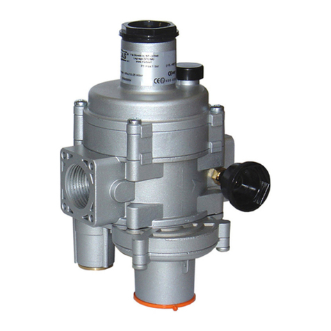
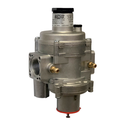
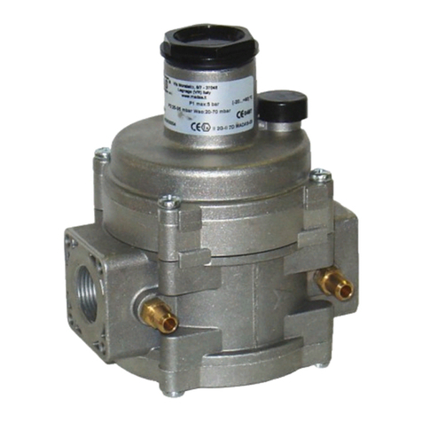
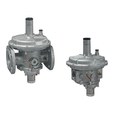
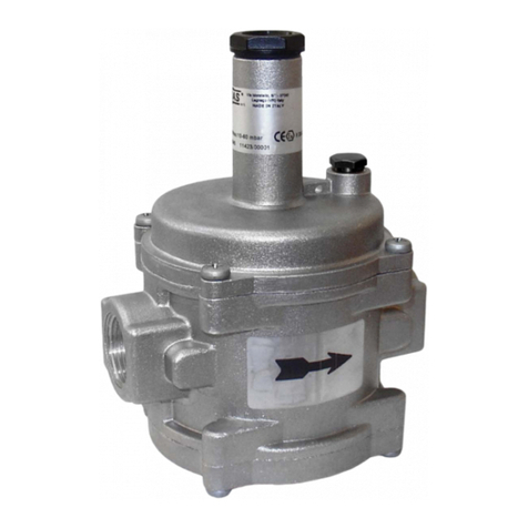
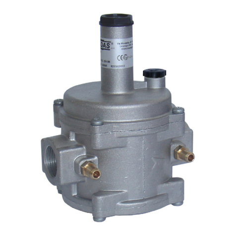
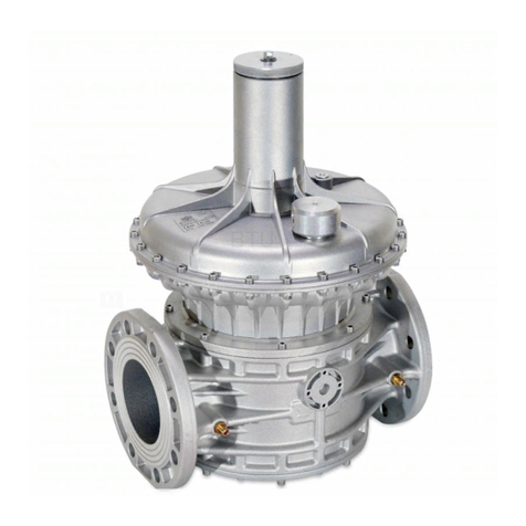
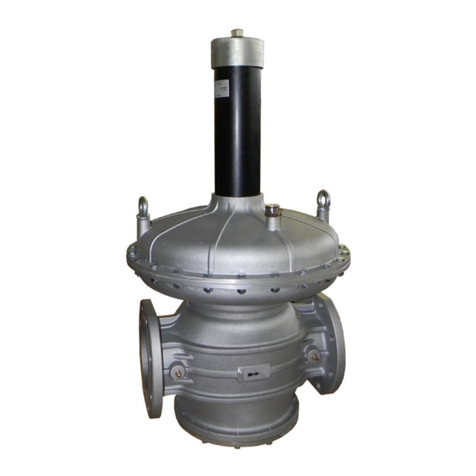
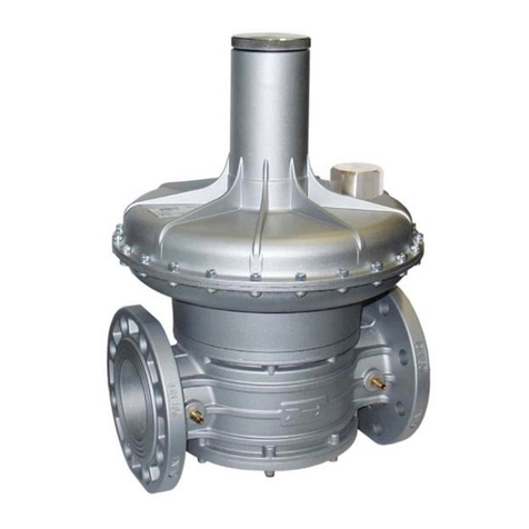
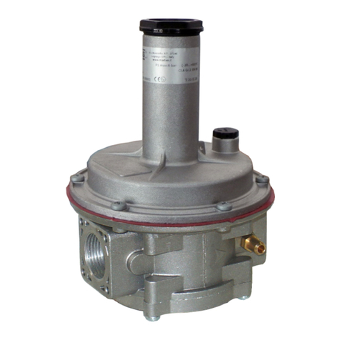
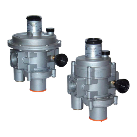
Madas FRG/2MCS9 User manual

GAS PRESSURE REGULATOR
FRG-RG/2MCS9
Pe: 0,5 ÷ 9 bar
DN15 - DN 20 - DN 25
EN

2
EN
INDEX
pag.
English ........................................................................................................................................................3
Drawings......................................................................................................................................................10
Flow data (table 1).............................................................................................................................................. 13
Dimensions (table 2) .....................................................................................................................................14
Regulation spring data (table 3) ....................................................................................................................... 15

3
EN
1.0 GENERAL INFORMATION
This manual shows you how to safely install, operate and use the device.
The instructions for use ALWAYS need to be available in the facility where the device is installed.
ATTENTION: installation/maintenance needs to be carried out by qualified staff (as explained in
section 1.3) by using suitable personal protective equipment (PPE).
For any information pertaining to installation/maintenance or in case of problems that cannot be solved with the instructions,
contact the manufacturer at the address and phone numbers provided on the last page.
1.1 DESCRIPTION
Device which supplies a preset and constant “downstream” pressure value (Pa) (within the intended operating limits) according
to variations in the inlet pressure (Pe) and/or the flow rate (Q). The compensated obturator ensures precision when adjusting
the outlet pressure (Pa) even with high and sudden variations in the inlet pressure.
These regulators are used in both civil and industrial installations where natural gas, LPG or other non-corrosive gases (dry
gases) are used.
Reference standards: EN 13611.
They can be equipped with the following safety devices and accessories according to the system requirements:
• relief valve: discharges small gas flows outwards if overpressure occurs downstream of the regulator. This discharge
can be conveyed outwards if the installation is in a poorly ventilated environment. They can also be supplied without the
relief valve.
• outlet pressure socket.
1.2 KEY TO SYMBOLS
ATTENTION: Attention
is drawn to the technical
details intended for
qualified staff.
DANGER: In the event of
inobservance, this may cause
damage to tangible goods, to people
and/or pets.
DANGER: In the event
of inobservance, this may
cause damage to tangible
goods.
1.3 QUALIFIED STAFF
These are people who:
•Are familiar with product installation, assembly, start-up and maintenance;
•Know the regulations in force in the region or country pertaining to installation and safety;
•Have first-aid training.
1.4 USING NONORIGINAL SPARE PARTS
•To perform maintenance or replace spare parts (e.g. spring, filter element, etc.) ONLY manufacturer-recommended parts
can be used. Using different parts not only voids the product warranty, it could compromise correct device operation.
•The manufacturer is not liable for malfunctions caused by unauthorised tampering or use of non-original spare parts.
1.5 IMPROPER USE
•The product must only be used for the purpose it was built for.
•It is not allowed to use fluids other than those expressly stated.
• The technical data provided on the rating plate must not, under any circumstances, be exceeded. The end user or installer is in
charge of implementing correct systems to protect the device, which prevent the maximum pressure indicated on the rating plate
from being exceeded.
•The manufacturer is not responsible for any damage caused by improper use of the device.

4
EN
2.0 TECHNICAL DATA
• Use : non-aggressive gases of the three families (dry gases)
• Ambient temperature : -20 - +60°C
• Minimum operating pressure : 0.5 bar
• Max operating pressure : 9 bar
• Allowable pressure PS : 9 bar
• Safety lock closing time : < 1 s
• Accuracy class : AC=10 - (Pa ± 10%)
• Closing pressure class : SG=10
• Relief valve : tested according to the indications in EN 334
• Connecting the vent : G 1/4
• Mechanical strength : Group 2 (according to EN 13611)
• Rp threaded connections : (DN 15 - DN 20 - DN 25) according to EN 10226
• NPT Threaded connections : on request
• Flanged connections that can couple with PN 16 flanges
: on request DN 25 with swivel flanges
• Standard filter element : filtering 50µm (on FRG... versions)
2.1 MODEL IDENTIFICATION
FRG/2MCS9: Pressure regulator with filter - Standard version
RG/2MCS9: Pressure regulator without filter - Standard version
3.0 COMMISSIONING THE DEVICE
3.1 OPERATIONS PRIOR TO INSTALLATION
•It is necessary to close the gas upstream of the device prior to installation;
• Make sure that the line pressure DOES NOT EXCEED the maximum pressure declared on the product label;
•Protective caps (if any) must be removed prior to installation;
•The pipes and inside of the device must be clear of any foreign bodies;
•IMPORTANT:
•to avoid possible pumping and/or disturbances in the gas flow, a straight pipe section equal to at least 5 DN must be
installed (downstream of the regulator);
•install manual gas closing devices (e.g. ball valves) upstream and downstream of the regulator to protect it from any
pipe leak test;
•do consider that if the regulator is equipped with a relief valve, the latter is suitable for small quantities of gas to be
discharged and CANNOT replace the relief valve installed separately as a specific device;

5
EN
If the device is threaded:
make sure that the pipe thread is not too long, to prevent damaging the body of the device when screwing it on;
If the device is flanged:
• make sure the inlet and outlet counter-flanges are perfectly coaxial and parallel in order to prevent unnecessary
mechanical stress to the body. Also calculate the space to insert the seal gasket;
• With regard to tightening operations, equip yourself with one or two calibrated torque wrenches or other controlled locking
tools;
•With outdoor installation, it is advisable to install a protective roof to prevent rain from oxidising or damaging parts of the
device.
•According to the plant geometry, check the risk of an explosive mixture arising inside the piping;
•If the regulator is installed near other devices or as part of an assembly, compatibility between the regulator and
these devices must be evaluated beforehand;
• Provide protection against impact or accidental contact if the device is accessible to unqualified personnel.
3.2 INSTALLATION (see example in 3.4)
Threaded devices:
•Assemble the device by screwing it, with the due seals, onto the plant with pipes and/or fittings whose threads are consistent
with the connection being attached;
•Do not use the neck of the top cover (3) as a lever to help you screw it on, but only use the specific tool;
•The arrow, shown on the body (14) of the device, needs to be pointing towards the application;
Flanged devices:
•Assemble the device by flanging it, with the due seals, onto the plant with pipes whose flanges are consistent with the
connection being attached. The gaskets must be free from defects and must be centred between the flanges;
• If, after installing the gaskets, there is still an excessive space in between, do not try to reduce the said gap by excessively
tightening the bolts of the device;
•The arrow, shown on the body (14) of the device, needs to be pointing towards the application;
•Insert the relative washers inside the bolts in order to prevent damage to the
flanges during tightening;
•When tightening, be careful not to “pinch” or damage the gasket;
•Tighten the nuts or bolts gradually, in a “cross” pattern (see the example
at the side);
•Tighten them, first by 30%, then by 60% and finally 100% of the maximum
torque (see the example alongside, according to EN 13611);
• Tighten each nut and bolt again clockwise at least once, until the maximum torque has been achieved uniformly;
Common procedures (threaded and flanged devices):
•The regulator is normally positioned before the application. Previously evaluate the possibility of installing the regulator as
shown in the installation example in 3.4;
• It can be installed in any position even if the installation shown in 3.4 (installation example) is preferred. A pressure outlet (15)
can be found outside the regulator, downstream from it, to control the regulation pressure (Pa);
•In STANDARD versions, it is recommended to connect the pulse outlet with a G 1/8 connection downstream of the regulator
(see installation example) if the gas flow exceeds 40 Nm3/h. To do so, remove the cap (21);
• Drain the relief valve (if any) outwards (as shown in 3.4) by removing the dust cap (18);
•It is always recommended to install a compensation joint;
•During installation, avoid debris or metal residues from getting into the device;
•To guarantee assembly free of any mechanical tension, we recommend using compensating joints, which also adjust to the
pipe’s thermal expansion;
•If the device is to be installed in a ramp, it is the installer’s responsibility to provide suitable supports or correctly sized
supports, to properly hold and secure the assembly. Never, for any reason whatsoever, leave the weight of the ramp only on
the connections (threaded or flanged) of the individual devices;
•In any case, after installation check the tightness of the system, without subjecting the diaphragm of the regulator (therefore,
the downstream pipe section) to a pressure higher than 300 mbar (valid only for versions with standard working diaphragm).
For versions with reinforced diaphragm, check the tightness with a pressure equal to 1.5 times the regulator setting pressure.
Diameter DN 25
Max. torque (N.m) 30
6
EN
12
3
4
5
6
7
8
piping
applicaon
3.3 GENERIC EXAMPLE OF AN INSTALLATION
1. Expansion joint/anti-vibration mount
2. Upstream ball valve
3. FRG/2MCS9 pressure regulator filter
4. Ball valve downstream of the regulator
If installed and subject to maintenance in full compliance with all conditions and technical instructions provided in this manual,
the device does not pose a source of specific hazards: in particular, under conditions of normal operation, the regulator is
expected to emit a flammable substance into the atmosphere only occasionally, and specifically:
The regulator can be dangerous with respect to the presence of other devices nearby if the integrated relief valve is triggered
or if the working diaphragm (17 ). If the diaphragm fails, the regulator becomes a source of explosive atmosphere emission of
continuous degree and, as such, it can generate hazardous areas 0 as defined in Directive 99/92/EC.
In particularly critical installation conditions (unattended areas, poor maintenance or poor ventilation) and especially if there are
potential sources of ignition and/or hazardous equipment near the regulator in regular operation, as they may generate electric
arcs or sparks, a preliminary assessment of the compatibility between the regulator and such equipment must be carried out.
In any case, every useful precaution must be adopted so as to prevent the regulator from generating zones 0: for example,
annually verify regular operation, possibility of changing the degree of emission of the source or intervening on the explosive
substance discharge by directing it outwards. To do so, simply remove the dust cap (18) by connecting the specific pipe (G
1/4) conveyed to the outside (see example of installation in 3.3).
discharge in
open air
discharge in
open air
G 1/8
G 1/4
Ø ext. min 8mm
Ø int. min 6mm
NOTE: The 5DN pipe connection can only be carried out on STANDARD versions (2MB).
5 DN
external roof
5. Vent valve
6. Relief valve MVS/1
7. Low pressure gauge and relative button
8. High pressure gauge and relative button

7
EN
4.0 FIRST STARTUP
Before commissioning, verify that:
•all of the instructions on the rating plate, including the direction of flow, are observed;
•the hole of the dust cap (18) is not clogged;
•IMPORTANT: The leak test of the piping must be performed without subjecting the diaphragm of the regulator
(therefore, the downstream pipe section) to a pressure higher than 300 mbar (for reinforced diaphragm 1.5 times
the regulator setting pressure). Use special manual gas closing devices to avoid damaging the regulator;
•The pressurisation manoeuvre of the equipment must be carried out very slowly so as to avoid possible damage.
NOTE: under no circumstances should a blind cap be placed instead of the dust cap (18) as the regulator may
not work;
•Open the downstream vent valve partially;
•Slowly open the upstream shut-off devices (e.g. solenoid valves, OPSO shut-off valve, etc.);
•Wait until the downstream pressure stabilises at the calibration value Pa of the spring (indicated on the rating plate);
•Close the vent valve;
•Check the tightness of all the system gaskets and check the internal/external tightness of the regulator;
•Open the downstream shut-off valve very slowly;
•Check the operation of the regulator.
5.0 CALIBRATION
Before carrying out the operations, make sure that the supplied spring/s is/are suitable for the desired Pa and differential
relief valve fields.
5.1 - Adjusting the relief valve (differential DfRv)
NOTE: The relief valve (if any) in these regulators is differential, therefore the range value (DfRv) indicated must be added to
the range value of the outlet pressure (Pa).
Example: Pa=20-30 mbar - DfRv=10-60 mbar.
Means that the relief valve can be calibrated from: (Pa min + DfRv min) = 20+10=30 mbar to: (Pa max + DfRv max) =
30+60=90 mbar
Therefore the effective range of the relief valve (in this case) is 30-90 mbar.
•Start the system and set the shut off as described in point 4.0;
•Slowly close the valve downstream of the regulator;
•Loosen and remove the cap (1);
•Use the 8 mm socket spanner (see fig. 1 and 2) to fully tighten the nut (20);
•Use the 8 mm socket spanner to press the adjustment nut (20) and increase the pressure Pa, reading it on the pressure
gauge, up to the desired setting value;
•Without pressing further, slowly loosen the adjustment nut (20) until the pressure Pa begins to decrease, shown on the
pressure gauge;
•In this case, the relief valve is set to the desired value;
•Remove the socket spanner and close the cap (1).

8
EN
5.2 - Adjusting the outlet pressure (Pa)
The outlet pressure Pa (unless specifically requested) is factory-set with the regulator installed as indicated in 3.4 and with the
adjustment screw (2) set approximately at the minimum setting value. The relief valve is set accordingly.
If the regulator is installed in different positions, check and reset the outlet pressure Pa, and consequently the devices
incorporated in the regulator;
Adjust the outlet pressure as follows:
•Unscrew the cap (1);
• Unscrew the adjustment screw (2) and set it to the minimum setting allowed (threaded end of the top cover (3))
;
•Start the system or make sure there is a minimum flow downstream of the regulator;
•To increase the pressure calibration downstream of the regulator, tighten the adjustment screw (2) to the desired value.
Perform the reading with a calibrated pressure gauge, installed downstream of the regulator to at least 5 DN (see example
in 3.3);
•Screw the cap (1) back on and if necessary, seal it in that position using the appropriate seal holes (if any);
•Use pressure outlets (15) on the device only for zero flow or very low flow measurements.
6.0 - RECOMMENDED PERIODIC CHECKS
•Use a suitable calibrated tool to ensure the bolts are tightened as indicated in 3.2;
•Check the tightness of the flanged/threaded connections on the system;
•Check the tightness and operation of the regulator/relief valve;
The final user or installer is responsible for defining the frequency of these checks based on the severity of the service conditions.
6.1 - CHECK THAT THE RELIEF VALVE IS WORKING PROPERLY
•Start the system as described in point 4.0;
•Slowly close the valve downstream of the regulator;
•Loosen and remove the cap (1);
•Use an 8 mm socket spanner to press the adjustment nut (20) to increase the pressure Pa above the preset value. Use a
calibrated pressure gauge for the reading;
•Remove the socket spanner. The generated overpressure will be discharged outwards and the Pa will begin to decrease to
the relief valve setting value. Relief valve operation is verified;
•Close the cap (1);
•Open the relief valve to discharge the created overpressure;
•Close the relief valve (the regulator goes to the closing pressure) and open the ball valve downstream of the regulator.
7.0 MAINTENANCE
•No maintenance operations need to be carried out inside the device. If operations must be carried out inside the
device (changing the spring, replacing the filter, etc.), it is advisable to contact the Technical Department. In any
case, before carrying out any dismantling operation on the device, make sure that there is no pressurised gas inside.
8.0 TRANSPORT, STORAGE AND DISPOSAL
• During transport the material needs to be handled with care, avoiding any impact or vibrations to the device;
• If the product has any surface treatments (ex. painting, cataphoresis, etc) it must not be damaged during transport;
• The transport and storage temperatures must observe the values provided on the rating plate;
• If the device is not installed immediately after delivery it must be correctly placed in storage in a dry and clean place;
• In humid facilities, it is necessary to use driers or heating to avoid condensation;
• At the end of its service life, the product must be disposed of in compliance with the legislation in force in the country where
this operation is performed.

9
EN
9.0 WARRANTY
The warranty conditions agreed with the manufacturer at the time of the supply apply.
Damage caused by:
• Improper use of the device;
• Failure to observe the requirements described in this document;
• Failure to observe the regulations pertaining to installation;
• Tampering, modification and use of non-original spare parts;
are not covered by the rights of the warranty or compensation for damage.
The warranty also excludes maintenance work, the assembly of parts or non-original spare parts, making changes to the
device and natural wear.
10.0 RATING PLATE DATA
The rating plate data (see examples above) includes the following:
• Manufacturer’s name/logo and address (possible distributor name/logo)
• Mod.: = name/model of the device followed by the connection diameter
• PS =
Allowable pressure
• Pe = Inlet pressure range that product operation is guaranteed at
• (-20...+60) °C = Temperature range within which product operation is guaranteed
• Pa = Outlet pressure range
• AC = Accuracy class Pa
• SG = Closing pressure class
• DfRv = Differential relief valve range with respect to Pa
• year = Year of manufacture
• Lot = Product serial number (see explanation below)
• U1823 = Lot issued in year 2018 in the 23rd week
• 14216 = progressive job order number for the indicated year
• 00001 = progressive number referring to the quantity of the lot
Mod.: FRG/2MCS9 DN 25 PS=Pe:0,5-9 bar (-20...+60)°C
Pa: 300-650 mbar DfRv:40-200 mbar AC10 SG10
year: 2018 Lot:U1823 14216/00001
Via Moratello, 5/7 - 37045
Legnago (VR) - Italy
www.madas.it

10
EN
fig. 1
FRG/2MCS9 - RG 2MCS9
8mm
For relief
valve setting Top part of the regulator with relief valve
G 1/4

11
EN
fig. 2
FRG/2MCS9
RG/2MCS9
DN 15 - DN 20 - DN 25
Top part of the regulator with or
without relief valve
RGFRG/2MCS9...
Required tool for setting Pa
with relief without relief
13mm

12
EN
fig. 1 and 2
1. Closing cap
2. Pa adjustment screw
3. Top cover
4. Pa Setting spring
5. Top disk for diaphragm
6. Top cover clamping screws
7. Compensation diaphragm
8. Filter element (only on FRG...)
9. Bottom
10. Bottom fastening screws
11. Centre pin
12. Obturator
13. Bottom sealing O-Ring
14. Body
15. Pressure test nipple (optional)
16. Flange
17. Working diaphragm
18. Dust cap
19. Relief valve setting spring
20. Relief valve regulation
21. Cap G 1/8 (external pulse outlet)

13
EN
Table 1
Flow data (m3/h gas)
P1
(bar)
P2 (mbar)
300 350 400 500 600 700 800 900 1000 1400 1800 2000 2500 3000
0,5 70 70 70 - - - - - - - - - - -
1180 200 200 200 160 - - - - - - - - -
2270 340 370 340 340 - - - - 50 50 - - -
2,5 - - - - - - - - - 80 100 - -
3 300 300 300 300 300 - - - - 90 105 150 - -
4 300 300 300 300 300 - - - - 115 150 230 - -
5 300 300 300 300 300 - - - - 140 190 290 - -
6 300 300 300 300 300 - - - - 220 320 320 - -
7 300 300 300 300 300 - - - - 270 320 320 - -
8 300 300 300 300 300 - - - - 270 320 320 - -
9 300 300 300 300 300 - - - - 270 320 320 - -
Air = 0,806
Natural Gas = 1
Town gas = 1.177
LPG = 0.62

14
EN
Table 2
Overall dimensions in mm
RG-FRG/2MCS9...
Threaded
connections
Flanged
connections A B C
DN 15 - DN 20 -
DN 25 -120 194 140
- DN 25 191 225 140
The dimensions are provided as a guideline, they are not binding
B
A
C

15
EN
Table 3
REGULATION SPRINGS DATA
FRG/2MCS9 RG/2MCS9
DN 15 DN 20 DN 25
Pa Setting springs
Range
(mbar)
Spring code dimensions in mm
(dx De x Lo x it)
170 ÷ 400* MO-1320 3,5x29,8x64x9
300 ÷ 650* MO-1305
3,5x29,8x98x11,5
600 ÷ 900* MO-2550 4x29x98x8
900 ÷ 1500 #MO-1305 3,5x29,8x98x11,5
1400 ÷ 2000 #MO-2550 4x29x98x8
1800 ÷ 3600 #MO-2590 4,5x29,5x94x10
DIFFERENTIAL RELIEF VALVE SPRINGS
40 ÷ 200* MO-2155 2x17x29x6
200 ÷ 800
#
MO-2155 2x17x29x6
* = versions with reinforced diaphragm 1. Settings marked with * are not interchangeable with #settings.
#= versions with reinforced diaphragm 2. Settings marked with * are not interchangeable with #settings.
it= total number of turns

Mod. MADAS IT372.00 E
Sede legale: Via V. Moratello, 5/6/7 - 37045 Z.A.I. Legnago (VR) Italy
Unità locale: Via M. Hack, 1/3/5 - 37045 Z.A.I. Legnago (VR) Italy
We reserve the right to any technical and construction changes.
This manual suits for next models
1
Table of contents
Other Madas Controllers manuals

Madas
Madas FRG/2MBCL User manual

Madas
Madas RG/2MCS User manual

Madas
Madas RG/2MT X Series User manual

Madas
Madas FRG/2MTZ User manual

Madas
Madas FRG/2MC User manual

Madas
Madas RG/2MC User manual

Madas
Madas FRG/2MBC User manual

Madas
Madas RG/2MBLZ User manual

Madas
Madas FRG-RG/2MCC User manual

Madas
Madas FRG-RG/2MCSH User manual
Popular Controllers manuals by other brands

AUTLED
AUTLED LC-002-012 user manual

ATTO Technology
ATTO Technology ThunderLink Desklink FC 1082 Getting started guide

Panasonic
Panasonic FP7 Series user manual

EFI
EFI E-42B Installation and service guide

Eurotherm
Eurotherm 2500 Engineering handbook

City Theatrical
City Theatrical QolorPIX 5850 Series user manual