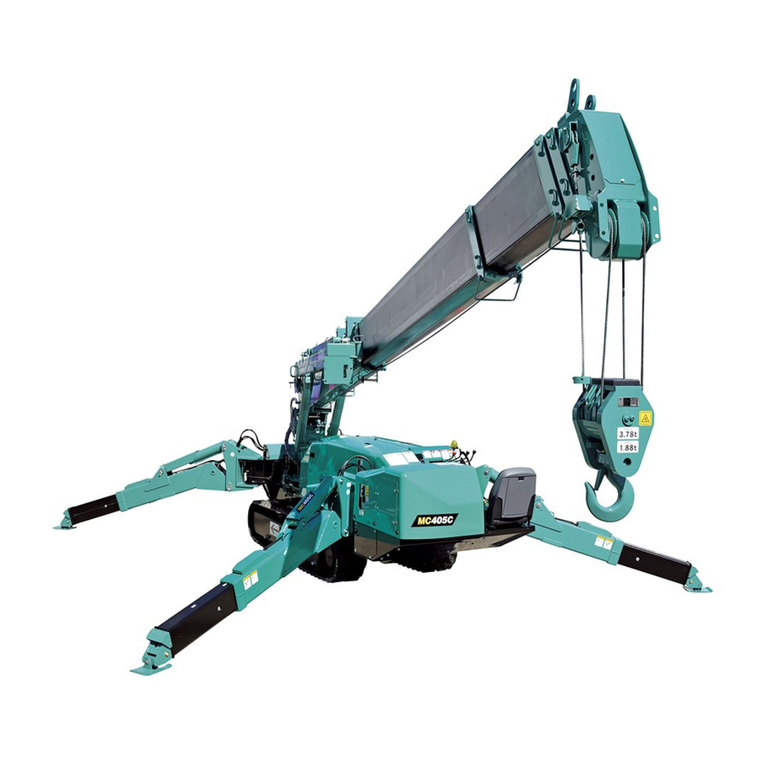
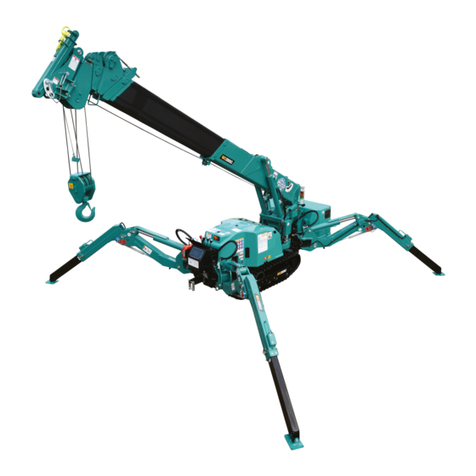
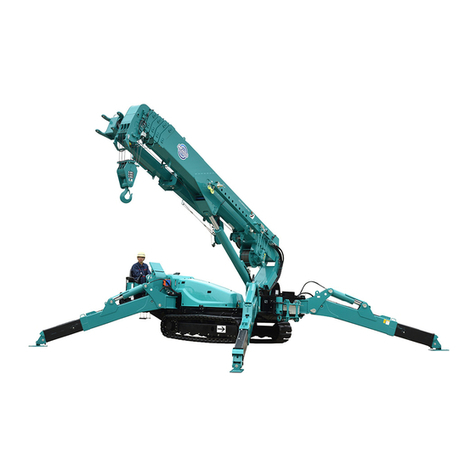
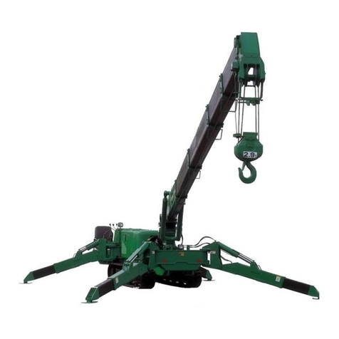
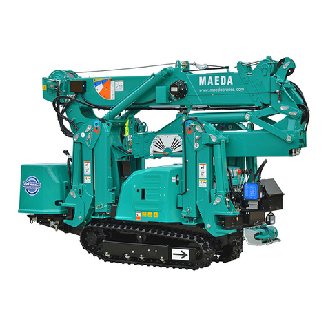
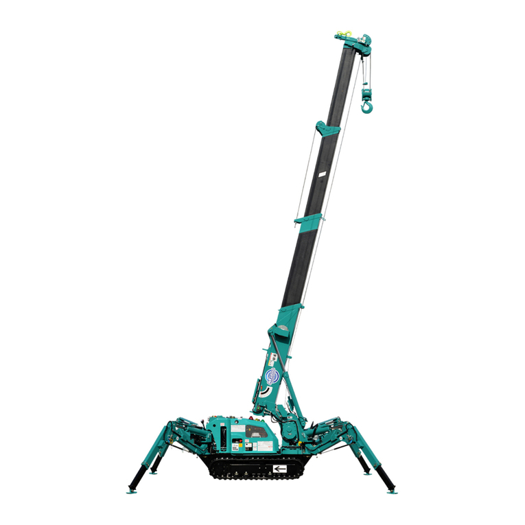
Maeda MC-104C-2 User manual

350E-OM0912-03
OPERATION MANUAL
MINI-CRAWLER CRANE
Serial No. M01736 and up
Unsafe use of this machine may cause serious injury or death. Operators
must read this manual before operating this machine. This manual should
be kept near the machine for reference and periodically reviewed by all
personnelwho willcomeinto contact withit.
NOTICE
MAEDA has Operation & Maintenance Manuals written in some other
languages. If a foreign language manual is necessary, contact your local
distributorfor availability.


0-1
CONTENTS
Item
Page
INTRODUCTION
1- 1
1. FOREWARD
1- 2
2. SAFETY INFORMATION
1- 3
3. OUTLINE OF THE MACHINE
1- 4
3.1 DESIGNATED TYPE OF WORK
1- 4
3.2 CONFIGURATION OF THE MACHINE
1- 4
3.3 FUNCTIONS THIS MACHINE IS PROVIDED WITH
1- 5
4. QUALIFICATION FOR OPERATING THE MACHINE
1- 5
4.1 QUALIFICATION REQUIRE FOR OPERATING CRANES
1- 5
5. GLOSSARY
1- 6
5.1 DEFINITIONS OF WORDS
1- 6
5.2 HOW TO READ WORKING RADIUS / LIFTING HEIGHT DIAGRAM
1- 7
5.3 HOW TO RATED TOTAL LOAD CHART
1- 8
5.4 HOW TO READ LOAD INDICATOR
1-12
SAFETY
2- 1
1. BASIC RULES
2- 2
2. RULES FOR OPERATION
2- 7
2.1 BEFORE STARTING UP ENGINE
2- 7
2.2 AFTER THE ENGINE HAS STARTED
2- 8
2.3 DURING CRANE OPERATION
2-12
3. RULES FOR TRANSPORTING A CRANE
2-18
4. RULES FOR HANDLING THE BATTERY
2-20
5. RULES TO OBSERVE IN CONNECTION WITH SERVICES
2-22
5.1 PRIOR TO CONDUCTING SERVICE
2-22
5.2 DURING SERVICE WORK
2-24
6. LOCATION FOR AFFIXING CAUTION PLATES
2-29
OPERATION
3- 1
1. NOMENCLATURE OF COMPONENTS
3- 2
1.1 NOMENCLATURE OF MACHINE COMPONENTS
3- 2
1.2 NOMENCLATURE OF TRAVEL CONTROL COMPONENTS
3- 3
1.2.1 CONTROL LEVERS
3- 4
1.2.2 SWITCHES
3- 6
1.2.3 METER, LAMP AND FUSES
3- 7
1.3 NOMENCLATURE OF CRANE CONTROL COMPONENTS
3- 8
1.3.1 CONTROL LEVERS
3- 9
1.3.2 SWITCHES
3-10
1.3.3 METERS AND LAMPS
3-11
1.4 OVER-HOIST PREVENTIVE DEVICE
3-12
1.5 EMO SWITCH (EMERGENCY STOP SWITCH)
3-13
1.6 OVER-LOWERING PREVENTION DEVICE
3-13
1.7 MACHINERY COVER
3-14

0-2
Item
Page
2. OPERATION CONTROL
3-15
2.1 INSPECTION PRIOR TO STARTING UP THE ENGINE
3-15
2.1.1 VISUAL CHECK
3-15
2.1.2 INSPECTION BEFORE STARTING YOUR WORK
3-17
2.2 STARTING UP THE ENGINE
3-23
2.2.1 STARTING UP THE ENGINE WITH MAIN STARTER SWITCH
3-23
2.2.2 STARTING UP THE ENGINE WITH AUXILIARY STARTER SWITCH
3-24
3.2.3 STARTING UP THE ENGINE WITH RECOIL STARTER IN USE
3-25
2.3 OPERATION AND CHECKING AFTER ENGINE HAS STARTED
3-26
2.4 BREAK-IN OPERATION
3-28
2.5 TRAVEL POSITION OF THE MACHINE
3-28
2.6 STARTING THE MACHINE
3-29
2.7 CHANGING TRAVEL DIRECTION OF THE MACHINE
3-30
2.8 STOPPING AND PARKING THE MACHINE
3-31
2.9 STOPPING THE ENGINE
3-32
2.10 INSPECTION AND CHECK AFTER STOPPING THE ENGINE
3-32
2.11 RULES FOR TRAVELING
3-33
2.12 SETTING UP THE OUTRIGGER
3-34
2.13 MATTERS TO BE KNOWN BEFORE STARTING CRANE WORK
3-39
2.14 OPERATIONS PRIOR TO STARTING CRANE WORK
3-40
2.15 CRANE WORK POSITION
3-41
2.16 HOISTING AND LOWERING OPERATION
3-42
2.17 BOOM DERRICKING AND LOWERING OPERATION
3-42
2.18 BOOM TELESCOPING OPERATION
3-43
2.19 SWING OPERATION
3-44
2.20 ACCELERATOR LEVER OPERATION
3-44
2.21 HOW TO USE LOAD INDICATOR AND LOAD METER
3-45
2.22 STOWING THE CRANE
3-47
2.23 STOWING THE OUTRIGGER
3-48
2.24 MATTERS PROHIBITED IN CONNECTION WITH CRANE OPERATION
3-51
3. HANDLING OF RUBBER TRACK
3-53
3.1 SMART WAY OF USING IT
3-53
3.2 WARRANTY
3-53
3.3 PROHIBITED TYPES OF WORK
3-54
3.4 RULE FOR USING IT
3-55
4. HANDLING OF WIRE ROPE
3-57
4.1 STANDARD FOR WIRE ROPE REPLACEMENT
3-57
4.2 MEASURES TO TAKE WHEN WINCH WIRE ROPE IS TWISTED
3-58
5. TRANSPORT
3-59
5.1 LOADING AND UNLOADING
3-59
5.2 HOW TO LIFT THE MACHINE
3-60
5.3 RULES FOR LOADING
3-61
5.4 RULE FOR TRANSPORT
3-61

0-3
Item
Page
6. HANDLINE IN COLD CLIMATE
3-62
6.1 PREPARATION FOR LOW AMBIENT TEMPERATURE
3-62
7. LONG TERM STARAGE
3-63
7.1 TREATMENT PRIOR TO STORAGE
3-63
7.2 DURING STORAGE
3-63
7.3 AFTER STORAGE
3-63
8. HANDLING OF BATTERY
3-64
8.1 RULES FOR HANDLING THE BATTERY
3-64
8.2 DE-MOUNTING AND MOUNTING THE BATTERY
3-65
8.3 RULES FOR CHARGING THE BATTERY
3-65
8.4 STARTING WITH BOOSTER CABLE IN USE
3-66
9. MEASURES TO BE TAKEN IN CASE OF ABNORMALITY
3-68
9.1 IN CONNECTION WITH ELECTRICAL COMPONENTS
3-68
9.2 IN CONNECTION WITH THE MACHINE
3-68
9.3 IN CONNECTION WITH ENGINE
3-69
INSPECTION AND MAINTENANCE
4- 1
1. RULES FOR CONDUCTING SERVICE
4- 2
2. BASICS OF SERVICE
4- 4
3. LEGALLY REQUIRED INSPECTION
4- 6
3.1 SAFETY REGULATION ON CRANE
4- 6
4. CONSUMABLE PARTS
4- 6
5. LUBRICATION OIL AND GREASE
4- 7
5.1 APPLICABLE LUBRICANTS BY AMBIENT TEMPERATURE
4- 7
6. STANDARD TOOLS AND STANDARD TIGHTENING TORQUE
4- 8
6.1 INQUIRY ON STANDARD TOOLS
4- 8
6.2 LIST OF STANDARD TIGHTENING TORQUE
4- 8
7. LIST OF INSPECTION AND SERVICE
4-11
8. WORKING PROCEDURE
4-13
8.1 FIRST 10 HOUR SERVICE
4-13
8.2 FIRST 20 HOUR SERVICE
4-13
8.3 FIRST 200 HOUR SERVICE
4-13
8.4 INSPECTION BEFORE STARTING YOUR WORK
4-13
8.5 IRREGULAR SERVICE
4-14
8.6 SERVICE IN EVERY 50 HOURS
4-29
8.7 SERVICE IN EVERY 100 HOURS
4-31
8.8 SERVICE IN EVERY 200 HOURS
4-32
8.9 SERVICE IN EVERY 500 HOURS
4-35
8.10 SERVICE IN EVERY 1000 HOURS
4-38
SPECIFICATIONS
5- 1
1. SPECIFICATIONS
5- 2
2. OVERALL DIMENSIONS
5- 3
3. TOTAL RATED LOAD CHART
5- 4
4. WORKING RANGE
5- 4

0-4

1-1
INTRODUCTION
1. FOREWORD
1-2
2. SAFETYINFORMATION
1-3
3.OUTLINEOFTHEMACHINE
1-4
4.QUALIFICATIONFOR OPERATINGTHEMACHINE
1-5
5.GLOSSARY
1-6

1-2
1. FOREWORD
Wethank youforselectingMaeda Mini-CrawlerCraneMC-104C.
This manual is the guide bookforyoursafeand efficient use of this machine.
Thismanualdescribesproceduresforoperationandserviceofthismachineaswellasmatterstobe
strictly observed while performingthem.
Most accidents are attributable to operation, inspection or service where basic safety rules are
neglected.
Beforeoperatingthismachine,please read this manualtofullyunderstandthemethodofoperation,
inspection andservice.
Unless the contentof this manual are observed, aserious accident could occur.
kWARNING
Careless use of this machine may result in serious injuryor death.
Operator and service personnel should read this manual carefully before starting
operation or service of this machine.
This manual should be kept in a designated location as a guide, and should be referred to
periodicallyby all the personnel involved.
・Do not use this machine unless and until the description in this manual is totally
understood.
・Always keep this manual readyand convenient for repeated reference.
・In case ofloss or damage,replace itimmediatelyby orderingfrom your dealer.
・Before transferring this machine, be sure to give this manual to the new owner.
・Any descriptions, value or illustrations, are based on the information at the time of
publication.
Due to continued improvement on this machine, the service standards, tightening
torque, pressure, measuring method, adjust value or illustration are subject to change.
Such change may effect the maintenance service work. Before starting your work,
contact the supplier to obtain the latest information.
・The description of safety is given in SAFETY INFORMATION on page 1-3 and in SAFETY
from page 2-1.

1-3
2. SAFETY INFORMATION
Forbetterunderstandingofthismanual andcautionplatesonthemachine,safetyrelated messagesareclassified
asfollows:
Indicatesapressingdangerthatmayresultindeathorseriousinjury. Alsoindicated
is the methodtoavoid suchrisk.
Indicatesatypeofdangerwhichishighlyprobabletoresultindeathorseriousinjury.
Alsoindicated isthemethodto avoidsuch risk.
Indicatesanystatuswhereit mayresultinlighttomediuminjuryorseriousdamage
to themachine. Alsoindicated isthemethod to avoid such risk.
Further,wehave shownwithfollowingcaptionswhatistobeobservedfor thesakeofthemachineandwhatis
convenienttoknow.
Indicatesthecasewhereimproperhandlingmaycausedamagetoorshortentheuseful
lifeofthemachine.
Informationwhichisconvenienttoknow.
Rulesdescribedinthismanualinconnectionwithproceduresandsafetyforoperationandservice,areapplicable
onlytothosecaseswherethismachineisusedfordesignatedwork.
Themanufactureris notin aposition tobeableto presume all thecasestowhich thismachinemaybeexposedby
users.
Accordingly,anyrules showninthismanual oronthecautionplates affixedto yourmachine doesnotcoverevery
situationrelevantto safety.
Forcarryingoutanyoperationormaintenanceservicenotdescribedinthismanual,itshouldbeunderstoodthat
necessarymeasuresforsafetyaresolelyforthe responsibilityoftheusers.
Evenfortheresponsibilityofusers,anywork oroperationexpresslyprohibitedinthismanualshouldneverbe
performed.
kDANGER
kWARNING
kCAUTION
CAUTION
NOTES

1-4
3. OUTLINE OF THE MACHINE
3.1 DESIGNATED TYPE OF WORK
Thismachineshouldbeused mainlyforthefollowingwork:
・Cranework
This machine is a mobile crane with a boom type crane mounted on rubbertracked undercarriage. It is capable of
self propelled movementonjobsitesand crane work within total rated load.
Inaddition.Thecabletype remotecontrollerisprovidedtoallowremotecontrolof thecrane.
3.2 CONFIGURATION OF THE MACHINE
①Undercarriage
②Crane
③Safetysystems
In this manual, front, rear, right and left are in principle identified respectively
while viewing forward from the operator seat. Above sketch shows the crane
in workingposition.
OUTERDIMENSIONSDRAWING

1-5
Thismachineconsistsoffollowingmajorcomponents:
[1] UNDERCARRIAGE
Consistsoftravelgear,engine,travel controlandcraneoperationsystems.
[2] CRANE
Consists ofboom telescoping,boom derricking,swingandhook-block winches and outriggersystems.
[3] SAFETY SYSTEMS
Hook over-hoist warning system,hydraulic safety valve, Travel/Crane work selector system (which prevents crane
from functioning while traveling) and Outrigger/Crane work selector system (prevents outrigger actuation while
performingcranework)areprovided.
3.3 FUNCTIONS THISMACHINE IS PROVIDED WITH
[1] UNDERCARRIAGE
・Thismachineisdesignedto bemorecompactwiththeoverallwidthfortravelingreducedfromthatof ourexisting
models,enablingittoentertighter spaces.
・Operationwithtwotravelleversallowspivotturnandspinturninadditiontonormaloperationofforward,backward
travelorturningitstraveldirection.
[2] CRANE
・Equippedwith auto-sliding type outrigger which allows the crane to work over uneven ground or in a tightspace.
Outriggerscanbeextendedinanywaytomatchterrainorconditionsofagivenjobsite.
・Boomtelescoping,hoistingandswingingmotionsplusverticalmoveofhookblockwithwinchoperation,permitsto
movesuspendedloadtodesiredlocationwithinratedtotalweightandworkingradius.
・Remotecontrolsystemallows remotecontrolof theoutriggersetting andanycranemotion.
4. QUALIFICATION FOR OPERATING THE MACHINE
kWARNING
・Workmen's accidents in connection with cranes are occurring frequently. What we would like our
users
to recognize isthefact that evenpersonswithrichexperience are incurring accidents.
・Foroperationof this machine,be sure to observesafetyrulesshowninthis manual.
4.1 QUALIFICATION REQUIRE FOR OPERATING CRANES
Qualification for operation of this type machine is provided in locallaws and regulations. Check with the competent
authorityoryourMaedadealer fordetail.

1-6
5. GLOSSARY
5.1 DEFINITIONS OF WORDS
[1] TOTAL RATED LOAD
Means the maximum load that can be lifted in accordance with length
and angle of the boom. Such load includesmass (weight) of hook and
rope.
[2] RATED LOAD
Means the load with the mass (weight) of hook and rope subtracted
fromtotalratedload,whichistheloadthat canbe lifted.
[3] WORKING RADIUS
Meansthehorizontaldistancefromswingcentertohookcenter.
[4] BOOM LENGTH
Thedistancefromboomfootpintosheavepinoftopboom.
[5] BOOM ANGLE
Theanglemadebetweenboomandhorizontalgroundline.
[6]LIFTINGHEIGHT ABOVE GROUND
Vertical distance from hook bottom to ground with the hook lifted to the
maximum (upperlimit).

1-7
5.2HOW TO READ WORKING RADIUS/LIFTING HEIGHT DIAGRAM
kWARNING
Theworkingradius/liftingheightdiagramindicatestherelation between theworking radius,boomangle
andlifting heightabovegroundofthis machine,withoutanyloadsuspended.
1. Point A in the sketch to the rightrepresents boom angle while point B
represents theliftingheightaboveground. WorkingradiusatpointsA
andBare thesame.
2. “Working radius/Lifting height Diagram”is bases on “no-load”without
takingintoconsiderationanybendingoftheboom.
In actuality, when load is lifted, the boom will bend causing the
workingradiustoslightlyexpand.
When working radius expands, the value of total rated load will be
reduced. It is important that you set your working plan with some
roomaddedtotheDiagram.

1-8
5.3 HOW TO READ TOTAL RATED LOAD CHART
kCAUTION
・Total rated load chart is based on level, hard ground. Depending on the outrigger setting or ground
conditions,machinemaytip over.
・Total rated load chart is based on working radius with bending of boom and lifted load taken into
consideration.
・If boom ②is extended to any extent, work should be performed within the capacity for the “3.00m
Boom”.
・When more than one half of the first mark is exposed from the boom①, work should be carried
outwithin the performance forthe"4.15m Boom".
・When more than one half or the second mark is exposed from boom ①, work should be carried
outwithin theperformance forthe"5.30m Boom".
・Ifworkingradius exceeds thevalueof Working Radius column in the chartbyanyextent,workshould
be performedwithin the totalrated load in thenext column of Working Radius.
・Totalratedload isshownwith themassof hook(15kg)included.
・Unless outrigger is extended to maximum, work should be performed in accordance with the “Total
rated loadChartwithoutextendingoutriggertomaximum”.
Totalrated load Chartshows the maximum loadthecraneiscapable ofliftingbytheworkingradius,inaccordance
with boomlengthandoutriggersetting.
[1] BOOM LENGTH
"1.85m boom", "3.00m boom", "4.15m boom" or "5.30m boom" as appears in top space of Total rated load Chart
represents respectivestatusasshown insketchesbelow:
1. "1.85mboom":Alltheboomsretracted.

1-9
2. "3.00mboom":Boomextendedtosuchextentthatthefirst markoftheboom(2)isexposed.
When the boom (2) is extended by any amount, however, work should be carried out according to the
performanceshowninthiscolumn.
3. "4.15m boom": Boom extended to such extent that the second mark of the boom (2) is exposed. When
more than one-half of the first mark of the boom (2) is exposed, too, your work should be carried out in
accordancewiththeperformanceofthiscolumn.
4. "5.30m boom":All theboomsextendedfully. Whenmore thanone-halfof thesecond mark oftheboom (2)
isexposedaswell,your workshouldbecarriedourinaccordancewiththeperformanceofthiscolumn.

1-10
[2] OUTRIGGERS EXTENDED TO THE MAXIMUM
kWARNING
・Forcranework, besuretoextendalltheoutriggers. Neverperformanycraneworkwithoutsettingup
outrigger. Machine maytip overcausing seriousinjuryotherwise.
・Outriggers should be extended while watching leveling instrument so that the machine is set
horizontally.
・Forworkingwithout extendingoutriggerto maximum,seethevaluesin "Totalrated load Chartwithout
extendingoutriggertomaximum"
Workingunder impropervaluemaycausethemachineto tip over.
・If you have retracted any positioning pin of outrigger inner box or outrigger base by even one hole,
your work should be performed in accordance with the value of "Total rated load with Outrigger
Ex-tendedtoother thanMaximum"
・Swinging360 degrees with a load lifted mayexpose the machineto an unstable position. Reduce the
workingradiusand usesufficient care.
”Outriggers extended to the maximum”at the top of Total rated load
Chartindicatesthestatusshowninthesketchtotheright.
NOTES
"With the Outrigger extended to maximum" means that, with the
outriggers set to the standard extension (60 degrees front and 45
degrees rear), inner boxes of all the outriggers pulled out fully and
linkage bracket positioning pins set at the maximum position, the
outriggersareplacedonlevelground.
Any status other than that in the sketch to the right represents
"Outrigger Extended to other than Maximum". See “OPERATION,2.12
HOW TOPLACE THE OUTRIGGERS"forproper placement.
NOTES
Even with all the outriggers extended to maximum, so long as the
grounding surface of any one of them is not flush with bottom surface
of track due to uneven terrain or the like, the status will have to be
definedas"OutriggersExtendedtootherthanMaximum".

1-11
[3] ZONES WHERE CRANE WORK IS PROHIBITED ACCORDING TO THE PATTERN OF
OUTRIGGER PLACEMENT.
kWARNING
・Sketchesbelow indicatethezoneswherecranework is prohibited according to the pattern ofoutrigger
placement (Shadowed area in the sketch). Within such zones, tipping-over of machine may take
placeto resultin seriouspersonalaccident. Neverattemptto perform craneworkin such zone.
・Of the 4 outriggers, the pair of either front and rear or right and left should always be set to the
standard placement (Front 60 degrees and rear 45 degrees). Even with the two outriggers set to
standard placement, the work should be performed in accordance with the value in Total rated load
ChartwithOutriggersExtended tootherthanMaximum.
・Outrigger placement wherebywork is allowed over entire circle, is only in accordance with "Standard
Extension" atthecenter in the sketch below.

1-12
5.4HOW TO READ LOAD INDICATOR
kWARNING
・For reading Total rated load with load indicator in use, be sure to observe following rules. Serious
accidentincludingtippingoveranddamaging ofthecranemaybeincurredotherwise:
1. Setup outriggerhorizontallyoverhard ground.
2. Extend outriggerto themaximum.
・Before lifting a load, determine the boom length to be used (number of stages) and boom angle,
compare the totalrated load at such position indicated byload indicatorwith the weight of the object
and make sure that the total load consisting of the weights of hook, object and rope never exceeds
the totalratedload.
・When the outrigger is not extended to the maximum, any total rated load value indicated on load
indicator is not useful. Read only the boom angle on the load indicator.Load indicator is affixed to
each sideofNo.1boomandconsistsofpointerandscaleboardasshown inthesketch totheright.
Load indicator indicates the total rated load with outrigger
setonhard,levelgroundandextendedtomaximum(See
“INTRODUCTION, 5.3 [2] OUTRIGGER EXTENDED
TO MAXIMUM”), excluding bending of the boom. The
load indicatorshouldberead tointhefollowingmanner:
・Read the value atthe intersection of curve on scale for
theboominuseandpointer. ItindicatestheTotalrated
load fortheboom lengthin useatthetime.

2-1
SAFETY
1. BASIC RULES
2- 2
2.RULESFOROPERATION
2- 7
3.RULESFORTRANSPORTINGACRANE
2-18
4. RULESFORHANDLINGTHEBATTERY
2-20
5. RULESTO OBSERVE INCONNECTIONWITH SERVICE
2-22
6. LOCATIONFORAFFIXINGCAUTION PLATES
2-29
kWARNING
Read and observe these safety related rules thoroughly. Violating
this manual can result in an accident involving serious injury or
death.

2-2
1. BASIC RULES
FOLLOW THEINSTRUCTION MANUAL AND CAUTION PLATES
•Read and understand this manual and caution plates affixed to the
machine. Operating the machine without fully understanding them may
lead to improperoperationresultinginan accidentinvolving personal injury
or damageto themachine.
•Understand proper method of using and servicing this machine to perform
operationsafely.
•This manual and caution plates on the machine should always be kept
legible. When they become illegible, replace them quickly by obtaining
fromyourdealer.
QUALIFICATION TO OPERATE
•Officialqualificationmayberequiredtooperate thismachine.
See“INTRODUCTION,4.QUALIFICATIONFOROPERATION”inthismanualfordetail.
•Operation of this machine normally requires certain official qualifications for mobile crane or small sized mobile
craneaswellasforperformingslingingwork. Checkwithyourlocalauthorityforrequiredqualifications
•Operator should receive sufficient training and acquire sufficient operating technique before starting to operate
thecrane.
PROTECTIVE ITEMS AND CLOTHING
•Besureto wearhardhat, safetyshoesandsafetybelt.
•Selectandwearprotectorsuitabletoparticularwork.
•Do not wearexcessively large clothing or accessory which may be caught
by control lever or other projection, causing the machine to make
unintendedmovement.
RULES FORSAFE OPERATION
•Followinstructionorsignalofmanagementandleader,to work with priorityplacedonsafety.
•Workwhileobservingthebasicsofcranework.
•Besuretoconductprescribedinspectionbeforestartingoperationandwork.
•Donotworkunderweatherconditionsofgale,thunderorfog.
•Neveroperatethemachine whenyouaretired,under theinfluence of alcohol orsleepinducingdrugs.
•For performing operation, inspection or service, be sure to observe working rules, safety regulations and
operatingprocedures.
•Pay attention to surroundings and pedestrians when working. When a pedestrian carelessly approaches,
suspend your work and take measures to give warning.
•Alwaysbealertwhileoperating themachineagainstunexpectedhappeningsandbereadytoaddressthem.
•Neveroperatethemachinebeyonditsperformanceorapplicationspecifiedinthismanual.
•Besuretoobserveprescribedtotalratedloadandworkingrange.
•Neveroperatethemachinelookingaside,recklesslyorforcibly.
•Pullout thekeywhenleavingoperationseat.
Table of contents
Other Maeda Construction Equipment manuals
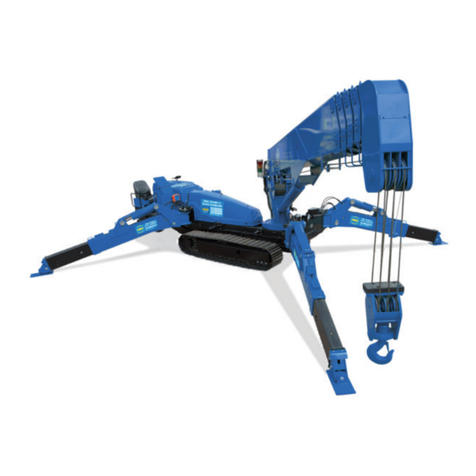
Maeda
Maeda LC785M-8B User manual

Maeda
Maeda LC1385M-8BF User manual

Maeda
Maeda MC405C-3 User manual

Maeda
Maeda MC305C-3 User manual

Maeda
Maeda LC1385M-8B User manual
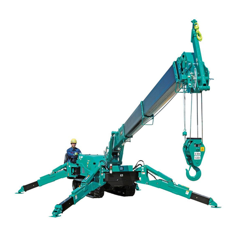
Maeda
Maeda CC1485S-1 User guide

Maeda
Maeda MC-305C-2 User guide

Maeda
Maeda MC285C-3 User manual

Maeda
Maeda CC1908S-1 User manual

Maeda
Maeda CC1485S-1 Installation manual

Maeda
Maeda MC174 User manual

Maeda
Maeda MC285C-2 User manual

Maeda
Maeda CC423S-1 User manual

Maeda
Maeda MC-305C-2 User manual

Maeda
Maeda MK1033C-1 User manual

Maeda
Maeda MC-174CRM User guide

Maeda
Maeda CC1908S-1 User manual

Maeda
Maeda MC-285C User guide

Maeda
Maeda MC405C-3 User manual

Maeda
Maeda HIRD MC815 User manual