12
NEDERLANDS
Verklaring van algemene gegevens
1 Vastzetknop
2 Trekschakelaar
3 Dikte-meter zacht staal
3,2 mm
4 Dikte-meter roesvrij staal
2,5 mm
5 Mond (3,5 mm opening)
6Sleutel
7 Sluitmoer
8 Matrijshouder
9 Stempel
10 Schroef
11 Loszetten
12 Snijkant
13 Groef
14 Pen
15 Stempelhouder
16 Slijpen/scherpen:
0,3 – 0,4 mm
17 Verwijder botte gedeelte
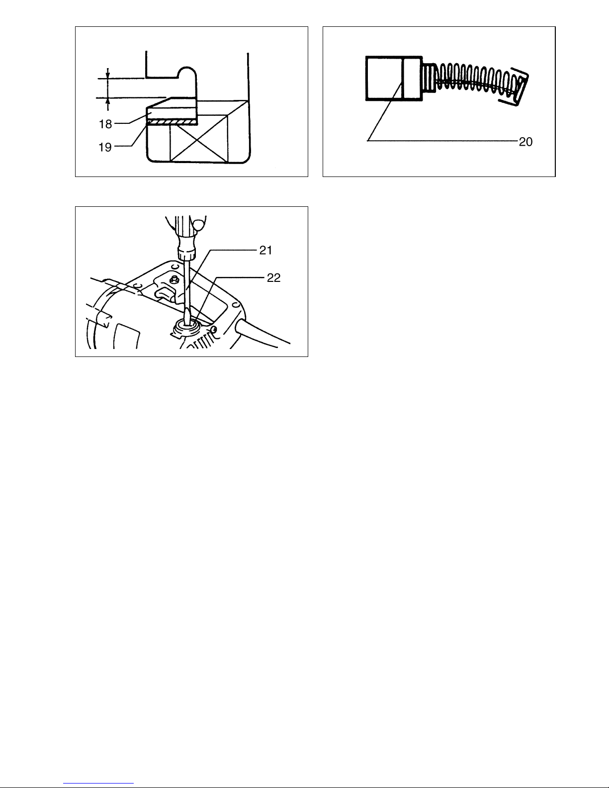
18 Matrijs
19 Sluitring
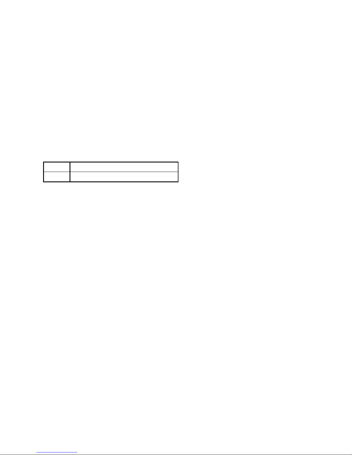
20 Limietaanduiding
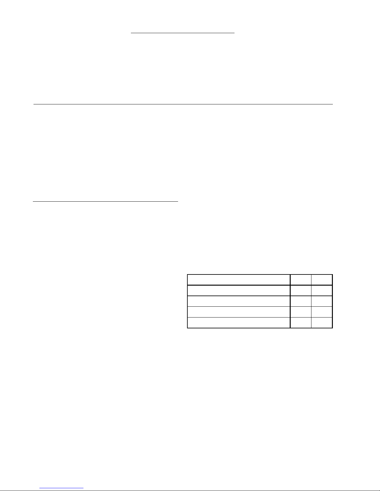
21 Schroevedraaier
22 Koolborsteldop
TECHNISCHE GEGEVENS
Model JN3200
Max. snijcapaciteit
Staal tot maximaal 400 N/mm2............... 3,2 mm/10 ga
Staal tot maximaal 600 N/mm2............... 2,5 mm/13 ga
Staal tot maximaal 800 N/mm2............... 1,0 mm/20 ga
Aluminium tot maximaal 200 N/mm2...... 2,5 mm/13 ga
Min. straal van snijcirkel
Buitenkant ....................................................... 128 mm
Binnenkant ...................................................... 120 mm
Aantal snijbewegingen/min. .................................... 1 300
Totale lengte ....................................................... 215 mm
Netto gewicht ......................................................... 3,4 kg
• In verband met ononderbroken research en ontwikke-
ling behouden wij ons het recht voor bovenstaande
technische gegevens te wijzigen zonder voorafgaande
kennisgeving.
• Opmerking: De technische gegevens kunnen van land
tot land verschillen.
Stroomvoorziening
De machine mag alleen worden aangesloten op een
stroombron van hetzelfde voltage als aangegeven op de
naamplaat, en kan alleen op enkel-fase wisselstroom
worden gebruikt. De machine is dubbel-geïsoleerd vol-
gens de Europese standaard en kan derhalve ook op
een niet-geaard stopcontact worden aangesloten.
Veiligheidswenken
Voor uw veiligheid dient u de bijgevoegde Veiligheids-
voorschriften nauwkeurig op te volgen.
AANVULLENDE
VEILIGHEIDSVOORSCHRIFTEN
1. Zorg er altijd voor dat de machine is uitgescha-
keld en de stekker uit het stopkontakt vooraleer
werken aan de machine uit te voeren.
2. Zorg ervoor dat het netsnoer steeds achter en uit
de buurt van de machine blijft.
3. Raak onmiddellijk na de werkzaamheden het
blad noch het werkstuk aan, aangezien het
gloeiend heet kan zijn en brandwonden kan ver-
oorzaken.
BEWAAR DEZE VOORSCHRIFTEN.
BEDIENINGSVOORSCHRIFTEN
Voorsmering
Smeer de snijlijn vooraf in met machineolie wanneer u
zacht staal of roestvrij staal gaat snijden; gebruik lichte
olie of petroleum wanneer u aluminium gaat snijden.
Werking van de trekschakelaar (Fig. 1)
LET OP:
Alvorens de machine op netstroom aan te sluiten, dient
u altijd te controleren of de trekschakelaar behoorlijk
werkt en bij het loslaten naar de “OFF” positie terugkeert.
Om de machine in te schakelen, drukt u gewoon de trek-
schakelaar in. Laat de schakelaar los om de machine uit
te schakelen. Voor continu gebruik, eerst de trekschake-
laar en dan de vastzetknop indrukken. Om de machine
vanuit de vergrendelde stand te stoppen, de trekschake-
laar helemaal indrukken en deze dan loslaten.
Toegestane snijdikte (Fig. 2)
De dikte van het te snijden materiaal hangt af van de
treksterkte van het materiaal zelf. De groef in de matrijs-
houder doet dienst als diktemeter. Probeer geen materi-
aal te snijden dat niet in deze groef past.
Deze machine snijdt elke aluminiumplaat die in de
machinemond (3,5 mm opening) past.
Max. snijcapaciteit mm ga
Staal tot maximaal 400 N/mm23,2 10
Staal tot maximaal 600 N/mm22,5 13
Staal tot maximaal 800 N/mm21,0 20
Aluminium tot maximaal 200 N/mm22,5 13