Makita JS3201 User manual

GB
Metal Shear Instruction Manual
F
Cisaille Manuel d’instructions
D
Blechschere Betriebsanleitung
I
Cesoia per metalli Istruzioni per l’uso
NL
Plaatschaar Gebruiksaanwijzing
E
Cizalla para Metal Manual de instrucciones
P
Tesoura Faca Manual de instruções
DK
Metalpladesaks Brugsanvisning
GR Ψαλίδι μετάλλων Οδηγίες χρήσεως
TR Metal Kesme MakinasıKullanma kılavuzu
JS3201

2
12
34
56
78
3
4
12
13
14
12
6
8
10
7
8
11
97
8
5
6
7
8
12
013363 013364
004679 013365
004683 004684
004685 013366
15

3
910
11 12
013367 004703
1800 mm
(70-7/8")
A
16
001145 013361
17
18
19

4
ENGLISH (Original instructions)
Explanation of general view
1 Switch trigger
2 Lock button
3 Gauge for stainless:
2.5 mm (3/32")
4 Gauge for mild steel:
3.2 mm (1/8")
5 Hex wrench
6 Lower blade
7 Upper blade securing bolt
8 Upper blade
9 Tighten
10 Blade holder
11 No gap allowed
12 Lower blade positioning bolt
13 Hex nut
14 Thickness gauge
15 Workholder
16 Cutting line
17 Limit mark
18 Screwdriver
19 Brush holder cap
SPECIFICATIONS
• Due to our continuing program of research and devel-
opment, the specifications herein are subject to change
without notice.
• Specifications may differ from country to country.
• Weight according to EPTA-Procedure 01/2003
ENE037-1
Intended use
The tool is intended for cutting sheet steel and stainless
sheet steel.
ENF002-2
Power supply
The tool should be connected only to a power supply of
the same voltage as indicated on the nameplate, and can
only be operated on single-phase AC supply. They are
double-insulated and can, therefore, also be used from
sockets without earth wire.
GEA010-1
General Power Tool Safety Warnings
WARNING Read all safety warnings and all
instructions. Failure to follow the warnings and
instructions may result in electric shock, fire and/or
serious injury.
Save all warnings and instructions for future
reference.
GEB027-3
SHEAR SAFETY WARNINGS
1. Hold the tool firmly.
2. Secure the workpiece firmly.
3. Keep hands away from moving parts.
4. Edges and chips of the workpiece are sharp.
Wear gloves. It is also recommended that you
put on thickly bottomed shoes to prevent injury.
5. Do not put the tool on the chips of the work-
piece. Otherwise it can cause damage and trou-
ble on the tool.
6. Do not leave the tool running. Operate the tool
only when hand-held.
7. Always be sure you have a firm footing.
Be sure no one is below when using the tool in
high locations.
8. Do not touch the blade or the workpiece immedi-
ately after operation; they may be extremely hot
and could burn your skin.
9. Avoid cutting electrical wires. It can cause seri-
ous accident by electric shock.
10. Do not operate the tool at no-load unnecessarily.
SAVE THESE INSTRUCTIONS.
WARNING:
DO NOT let comfort or familiarity with product
(gained from repeated use) replace strict adherence
to safety rules for the subject product. MISUSE or
failure to follow the safety rules stated in this instruc-
tion manual may cause serious personal injury.
Model JS3201
Max. cutting capacities
Steel up to 400 N/mm23.2 mm (10 ga.)
Steel up to 600 N/mm22.5 mm (13 ga.)
Steel up to 800 N/mm21.5 mm (17 ga.)
Aluminum up to 200 N/mm24.0 mm (9 ga.)
Min. cutting radius 50 mm
Strokes per minute (min–1) 1,600
Overall length 213 mm
Net weight 3.4 kg
Safety class /II

5
FUNCTIONAL DESCRIPTION
CAUTION:
• Always be sure that the tool is switched off and
unplugged before adjusting or checking function on the
tool.
Switch action (Fig. 1)
CAUTION:
• Before plugging in the tool, always check to see that
the switch trigger actuates properly and returns to the
“OFF” position when released.
• Switch can be locked in “ON” position for ease of oper-
ator comfort during extended use. Apply caution when
locking tool in “ON” position and maintain firm grasp on
tool.
To start the tool, simply pull the switch trigger. Release
the switch trigger to stop.
For continuous operation, pull the switch trigger and then
push in the lock button.
To stop the tool from the locked position, pull the switch
trigger fully, then release it.
Permissible shearing thickness (Fig. 2)
The groove on the yoke serves as a thickness gauge for
shearing mild or stainless steel plate. If the material fits
within the groove, it is shearable.
The thickness of materials to be sheared depends upon
the type (strength) of the material. The maximum shear-
ing thickness is indicated in the table below in terms of
various materials. Attempting to shear materials thicker
than indicated will result in tool breakdown and/or possi-
ble injury. Keep within the thickness shown in the table.
006426
ASSEMBLY
CAUTION:
• Always be sure that the tool is switched off and
unplugged before carrying out any work on the tool.
Blade inspection
Before using the tool, check the blades for wear. Dull,
worn blades will result in poor shearing action, and the
service life of the tool will be shortened.
The service life of the blades varies in terms of the mate-
rials to be cut and the fixed blade clearance.
Roughly speaking, a blade can cut about 500 m of
3.2 mm mild steel with one cutting edge (total 2,000 m
with four cutting edges).
Rotating or replacing blades (Fig. 3, 4, 5, 6 & 7)
Both the upper and lower blades have four cutting edges
on each side (the front and back). When the cutting edge
becomes dull, rotate both the upper and the lower blades
90° to expose new cutting edges.
When all eight edges are dull on both the upper and
lower blades, replace both blades with new ones. Each
time blades are rotated or replaced, proceed as follows.
Remove the blade securing bolts with the hex wrench
provided and then rotate or replace the blades.
Install the upper blade and tighten the upper blade secur-
ing bolt with the hex wrench. Press up on the upper
blade while tightening it.
After securing the upper blade, be sure that there is no
gap left between the upper blade and the beveled sur-
face of the blade holder.
Then install the lower blade like the upper blade while
adjusting the clearance between the upper blade and
lower blades. When performing this adjustment, the
upper blade should be in the lowered position.
First, semi- tighten the lower blade securing bolt, then
insert the thickness gauge for the desired clearance.
The cutting thickness is indicated on the thickness gauge
so the combinations shown in the table below should be
used. Work the lower blade positioning bolt on the yoke
until the clearance is such that the thickness gauge
moves only with some difficulty. Then firmly tighten the
lower blade securing bolt. Finally, tighten the hex nut to
secure the lower blade positioning bolt.
Thickness gauge combinations
006427
OPERATION
CAUTION:
• When cutting, always place the shear on the workpiece
so that the material cut away is positioned on the right
side to the operator.
• Hold the tool firmly with one hand on the main handle
when performing the tool.
Holding material (Fig. 8)
The materials for cutting should be fastened to the work-
bench by means of workholders.
Shearing method (Fig. 9)
For smooth cuts, tip the tool slightly backward while
advancing it.
Maximum cutting width (Fig. 10)
Stay within the specified maximum cutting width (A):
Case of length 1,800 mm.
006432
Minimum cutting radius
Minimum cutting radius is 50 mm when cutting 2.3 mm
mild steel.
Max. cutting capacities mm ga.
Steel up to 400 N/mm23.2 10
Steel up to 600 N/mm22.5 13
Steel up to 800 N/mm21.5 17
Aluminum up to 200 N/mm24.0 9
Material thick-
ness
2.3 mm
(14 ga.)
2.5 mm
(13 ga.)
3.2 mm
(10 ga.)
Thickness gauge
combinations 1.0 + 1.5 1.0 + 1.5 1.5 + 2.0
Mild steel (thickness) 3.2 mm Under 2.3 mm
Max. cutting width (A) 90 mm No limit
Stainless (thickness) 2.5 mm Under 2.0 mm
Max. cutting width (A) 70 mm No limit

6
MAINTENANCE
CAUTION:
• Always be sure that the tool is switched off and
unplugged before attempting to perform inspection or
maintenance.
• Never use gasoline, benzine, thinner, alcohol or the
like. Discoloration, deformation or cracks may result.
The tool and its air vents have to be kept clean. Regularly
clean the tool’s air vents or whenever the vents start to
become obstructed.
Replacing carbon brushes (Fig. 11 & 12)
Remove and check the carbon brushes regularly.
Replace when they wear down to the limit mark. Keep
the carbon brushes clean and free to slip in the holders.
Both carbon brushes should be replaced at the same
time. Use only identical carbon brushes.
Use a screwdriver to remove the brush holder caps. Take
out the worn carbon brushes, insert the new ones and
secure the brush holder caps.
To maintain product SAFETY and RELIABILITY, repairs,
any other maintenance or adjustment should be per-
formed by Makita Authorized Service Centers, always
using Makita replacement parts.
OPTIONAL ACCESSORIES
CAUTION:
• These accessories or attachments are recommended
for use with your Makita tool specified in this manual.
The use of any other accessories or attachments might
present a risk of injury to persons. Only use accessory
or attachment for its stated purpose.
If you need any assistance for more details regarding
these accessories, ask your local Makita Service Center.
• Blades
• Hex wrench
• Thickness gauge
NOTE:
• Some items in the list may be included in the tool pack-
age as standard accessories. They may differ from
country to country.
ENG905-1
Noise
The typical A-weighted noise level determined according
to EN60745:
Sound pressure level (LpA): 81 dB (A)
Sound power level (LWA): 92 dB (A)
Uncertainty (K): 3 dB (A)
Wear ear protection
ENG900-1
Vibration
The vibration total value (tri-axial vector sum) determined
according to EN60745:
Work mode: cutting sheet metal
Vibration emission (ah): 17.0 m/s2
Uncertainty (K): 1.5 m/s2
ENG901-1
• The declared vibration emission value has been mea-
sured in accordance with the standard test method and
may be used for comparing one tool with another.
• The declared vibration emission value may also be
used in a preliminary assessment of exposure.
WARNING:
• The vibration emission during actual use of the power
tool can differ from the declared emission value
depending on the ways in which the tool is used.
• Be sure to identify safety measures to protect the oper-
ator that are based on an estimation of exposure in the
actual conditions of use (taking account of all parts of
the operating cycle such as the times when the tool is
switched off and when it is running idle in addition to
the trigger time).
ENH101-16
For European countries only
EC Declaration of Conformity
We Makita Corporation as the responsible
manufacturer declare that the following Makita
machine(s):
Designation of Machine:
Metal Shear
Model No./ Type: JS3201
are of series production and
Conforms to the following European Directives:
2006/42/EC
And are manufactured in accordance with the following
standards or standardised documents:
EN60745
The technical documentation is kept by:
Makita International Europe Ltd.
Technical Department,
Michigan Drive, Tongwell,
Milton Keynes, Bucks MK15 8JD, England
17.5.2012
Tomoyasu Kato
Director
Makita Corporation
3-11-8, Sumiyoshi-cho,
Anjo, Aichi, 446-8502, JAPAN

19
NEDERLANDS (Originele instructies)
Verklaring van algemene gegevens
1 Trekkerschakelaar
2 Vergrendelknop
3 Maat voor roestvrijstaaldikte:
2,5 mm (3/32")
4 Maat voor zachtstaaldikte:
3,2 mm (1/8")
5 Zeskant-inbussleutel
6 Onderste mes
7 Borgbout bovenste mes
8 Bovenste mes
9 Vastdraaien
10 Meshouder
11 Geen kier of speling openlaten
12 Instelbout onderste mes
13 Zeskantmoer
14 Diktemaat
15 Werkstukhouder
16 Kniplijn
17 Limietmarkering
18 Schroevendraaier
19 Borstelhouderdop
TECHNISCHE GEGEVENS
• Vanwege ons voortgaand onderzoeks- en
ontwikkelingsprogramma kunnen de bijgaande
technische gegevens zonder voorafgaande
kennisgeving worden gewijzigd.
• De technische gegevens kunnen van land tot land
verschillen.
• Gewicht volgens de EPTA-procedure 01/2003
ENE037-1
Doeleinden van gebruik
Dit gereedschap is bedoeld voor het knippen van
staalplaat en roestvrijstaalplaat.
ENF002-2
Stroomvoorziening
Het gereedschap mag alleen worden aangesloten op
een stroombron van hetzelfde voltage als aangegeven
op de naamplaat, en kan alleen op enkel-fase
wisselstroom worden gebruikt. Het gereedschap is
dubbel-geïsoleerd en kan derhalve ook op een niet-
geaard stopcontact worden aangesloten.
GEA010-1
Algemene veiligheidswaarschuwingen voor
elektrisch gereedschap
WAARSCHUWING! Lees alle
veiligheidswaarschuwingen en alle instructies. Het
niet volgen van de waarschuwingen en instructies kan
leiden tot elektrische schokken, brand en/of ernstig
letsel.
Bewaar alle waarschuwingen en instructies om in de
toekomst te kunnen raadplegen.
GEB027-3
VEILIGHEIDSVOORSCHRIFTEN VOOR DE
PLAATSCHAAR
1. Houd het gereedschap stevig vast.
2. Zet uw werkstuk stevig vast.
3. Kom met uw handen niet te dicht bij bewegende
onderdelen.
4. De randen en afgeknipte spaanders van het
werkstuk zijn uiterst scherp.
Draag handschoenen. Draag bij voorkeur ook
schoenen met dikke zolen, om eventuele
verwondingen te voorkomen.
5. Plaats het gereedschap niet op de afgeknipte
spaanders van het werkstuk. Dit kan
beschadiging en defect van het gereedschap
veroorzaken.
6. Laat het gereedschap niet ingeschakeld achter.
Schakel het gereedschap alleen in wanneer u het
stevig vasthoudt.
7. Zorg ook altijd dat u stevig op een solide bodem
staat.
Let bij het werken op hoge plaatsen op dat er
zich niemand recht onder u bevindt.
8. Raak het mes of het werkstuk onmiddellijk na
het werk nog niet aan; deze kunnen gloeiend
heet zijn en brandwonden veroorzaken.
9. Pas op dat u niet in elektrische draden snijdt. Dat
kan elektrische schokken en ernstige
ongelukken veroorzaken.
10. Laat het gereedschap niet onnodig lang draaien
in onbelaste toestand.
BEWAAR DEZE VOORSCHRIFTEN.
Model JS3201
Maximale snijcapaciteit
Staal tot maximaal 400 N/mm23,2 mm (10 ga.)
Staal tot maximaal 600 N/mm22,5 mm (13 ga.)
Staal tot maximaal 800 N/mm21,5 mm (17 ga.)
Aluminium tot maximaal 200 N/mm24,0 mm (9 ga.)
Minimale snijcirkel 50 mm
Aantal snijbewegingen per minuut (min–1)1600
Totale lengte 213 mm
Nettogewicht 3,4 kg
Veiligheidsklasse /II

20
WAARSCHUWING:
LAAT NIET uw vertrouwdheid met het gereedschap
(na regelmatig gebruik) omslaan in slordigheid of
onachtzaamheid omtrent de strikt na te leven
veiligheidsvoorschriften voor dit product.
VERKEERD GEBRUIK of het niet naleven van de
veiligheidsvoorschriften in deze gebruiksaanwijzing
kan leiden tot ernstige verwondingen.
BESCHRIJVING VAN DE FUNCTIES
LET OP:
• Zorg altijd dat het gereedschap is uitgeschakeld en de
stekker uit het stopcontact is verwijderd alvorens de
functies op het gereedschap te controleren of af te
stellen.
Werking van de schakelaar (Fig. 1)
LET OP:
• Controleer voordat u de stekker in het stopcontact
steekt, altijd even of de trekkerschakelaar goed werkt
en bij loslaten naar de “UIT”-stand terugkeert.
• De schakelaar kan in de “AAN”-stand vergrendeld
worden, hetgeen bij langdurig gebruik comfortabeler
werkt. Wees extra voorzichtig wanneer u de schakelaar
in de “AAN”-stand vergrendelt en houd het
gereedschap altijd stevig vast.
Om het gereedschap te starten, drukt u enkel de
trekkerschakelaar in. Laat de trekkerschakelaar los om
te stoppen.
Voor continu gebruik houdt u de trekkerschakelaar
ingedrukt en drukt u daarbij de vergrendelknop in.
Om het gereedschap te stoppen vanuit de vergrendelde
stand, drukt u de trekkerschakelaar helemaal in en laat u
die vervolgens los.
Toegestane snijdikte (Fig. 2)
De groef in het juk doet dienst als diktemaat voor de te
knippen zachtstaalplaat of roestvrijstaalplaat. Als het
materiaal in de groef past, kan het gereedschap dit
knippen.
De dikte van het door te knippen materiaal hangt af van
het soort materiaal (de treksterkte ervan). De maximale
knipdikte voor diverse materialen wordt in de tabel
hieronder aangegeven. Probeer niet om materialen te
knippen met een grotere dikte dan hier staat
aangegeven, want dat kan leiden tot defecten aan het
gereedschap en/of lichamelijk letsel. Werk dus altijd
binnen de dikte die in de tabel staat aangegeven.
006426
INEENZETTEN
LET OP:
• Zorg altijd dat het gereedschap is uitgeschakeld en de
stekker uit het stopcontact is verwijderd alvorens enig
werk aan het gereedschap uit te voeren.
Controle van de messen
Controleer vóór het gebruik van het gereedschap altijd
eerst de messen op slijtage. Botte of versleten messen
veroorzaken een slechte knipbeweging en verkorten de
levensduur van het gereedschap.
De levensduur van de messen hangt af van het te
snijden materiaal en de ingestelde tussenruimte van de
messen.
Over het algemeen kan een mes ongeveer 500 m aan
3,2 mm dik zacht staal knippen met een enkele snijrand
(dus in totaal 2 000 m met vier snijranden).
Draaien of vervangen van de snijmessen (Fig. 3,
4, 5, 6 en 7)
Zowel het bovenste als het onderste mes heeft aan beide
kanten (de voor- en achterkant) vier snijranden. Wanneer
de snijrand bot geworden is, dient u het bovenste en
onderste mes 90° te draaien zodat de nieuwe snijranden
zichtbaar worden.
Wanneer alle acht randen van zowel het onderste als het
bovenste mes bot geworden zijn, dient u beide messen
door nieuwe te vervangen. Telkens wanneer u de
messen draait of vernieuwt, gaat u als volgt te werk.
Verwijder de borgbouten van de messen met de
bijgeleverde zeskant-inbussleutel en draai of vernieuw
daarna de messen.
Monteer het bovenste mes en zet de borgbout van het
bovenste mes vast met de zeskant-inbussleutel. Druk
het bovenste mes omhoog terwijl u de bout vastzet.
Na het vastzetten van het bovenste mes dient u op te
letten dat er geen kier of speling open blijft tussen het
bovenste mes en het afgeschuinde oppervlak van de
meshouder.
Monteer dan het onderste mes net als het bovenste mes
en stel daarbij de afstand tussen het bovenste en het
onderste mes naar vereist in. Bij het maken van deze
instelling moet het bovenste mes in de verlaagde stand
staan.
Draai eerst de borgbout van het onderste mes ietwat
vast en steek dan de diktemaat er in om de gewenste
speling te bepalen.
De snijdikte wordt aangegeven op de diktemaat, dus
gebruikt u de combinaties aangegeven in de
onderstaande tabel. Verdraai de instelbout van het
onderste mes op het juk totdat de speling zodanig is dat
de diktemaat nauwelijks meer te bewegen is. Draai
vervolgens de borgbout van het onderste mes stevig
vast. Draai tenslotte de zeskantmoer stevig aan om de
instelbout van het onderste mes vast te zetten.
Combinaties van de diktemaat
006427
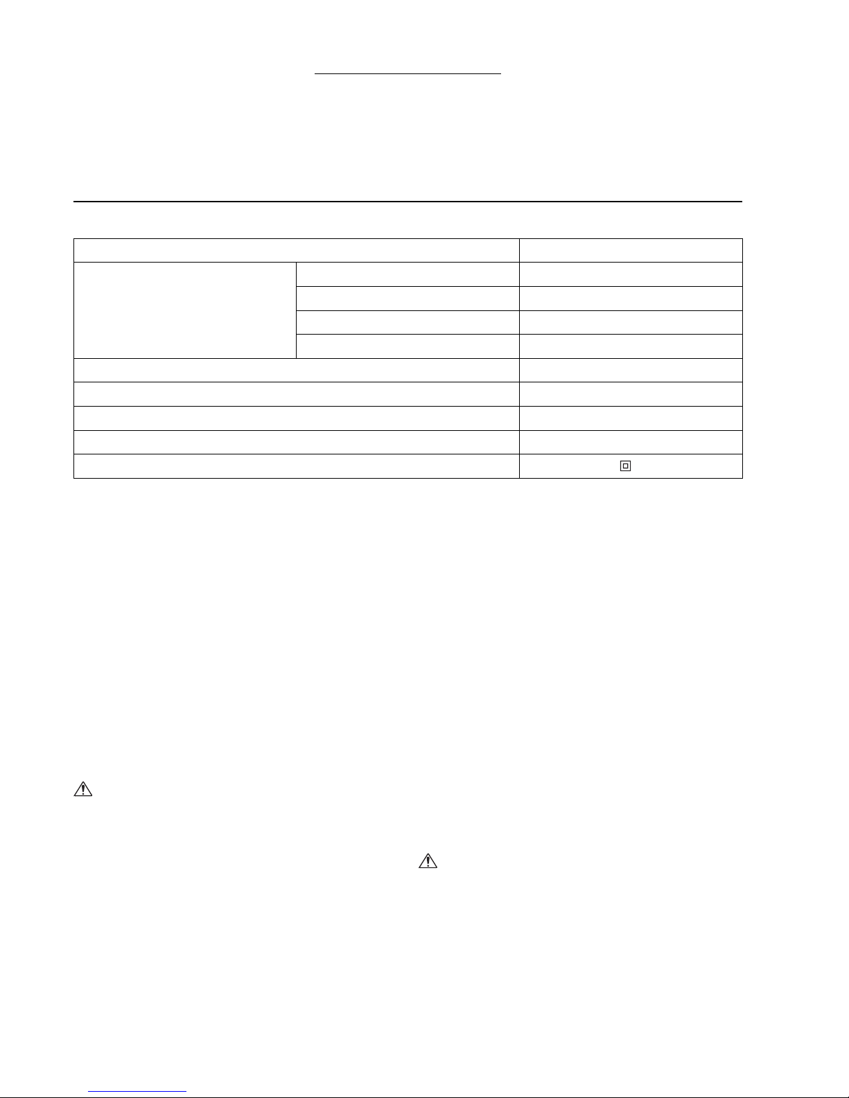
Maximale snijcapaciteit mm ga.
Staal tot maximaal 400 N/mm23,2 10
Staal tot maximaal 600 N/mm22,5 13
Staal tot maximaal 800 N/mm21,5 17
Aluminium tot maximaal 200 N/mm24,0 9
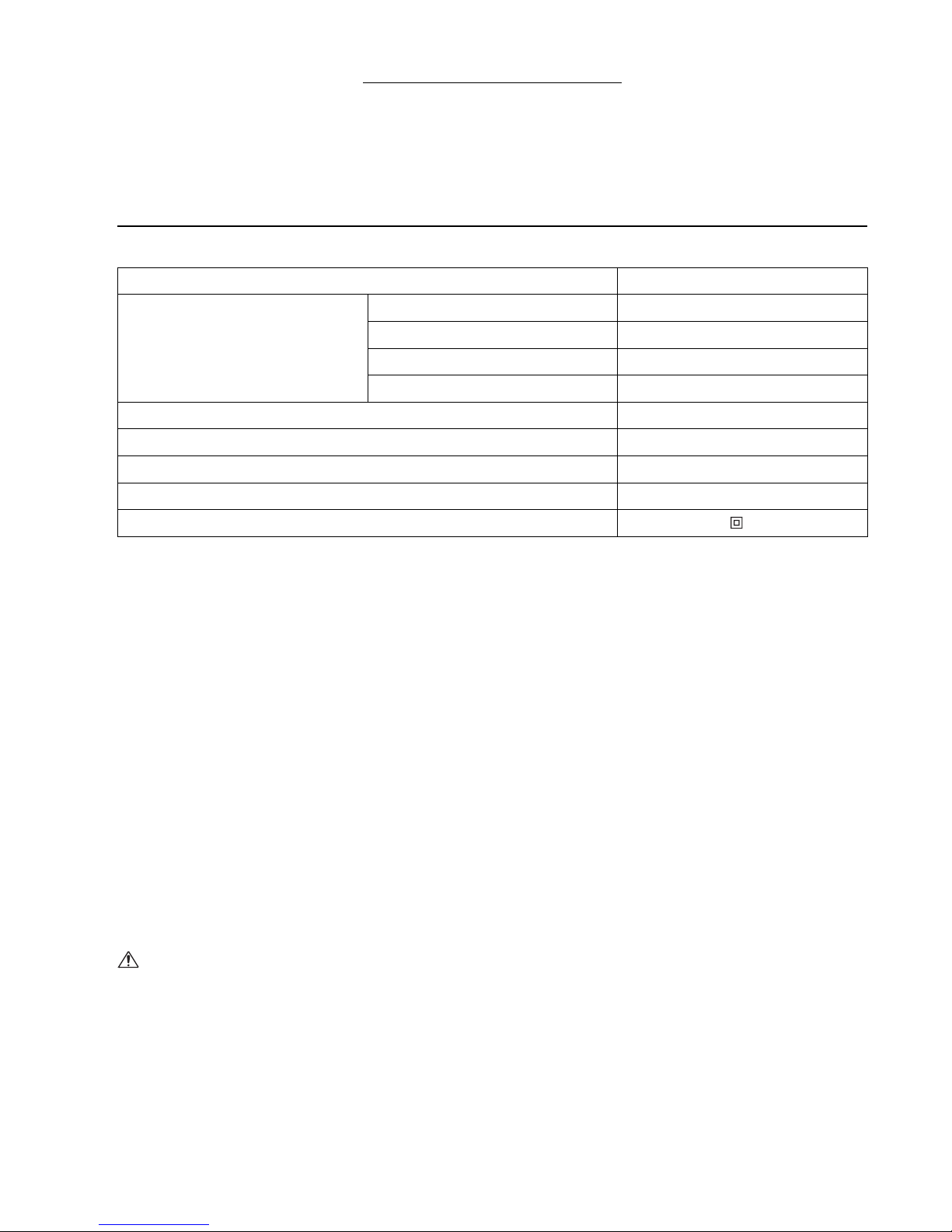
Dikte materiaal 2,3 mm
(14 ga.)
2,5 mm
(13 ga.)
3,2 mm
(10 ga.)
Combinaties van
de diktemaat 1,0 + 1,5 1,0 + 1,5 1,5 + 2,0

21
BEDIENING
LET OP:
• Voor het knippen plaatst u de plaatschaar zo op het
werkstuk dat het afgeknipte materiaal aan de
rechterkant van de gebruiker komt.
• Houd het gereedschap bij gebruik altijd stevig vast met
één hand aan de handgreep.
Materiaal vastzetten (Fig. 8)
De te knippen materialen moeten op de werkbank
worden vastgezet met behulp van geschikte
werkklemmen.
Gelijkmatig snijden (Fig. 9)
Voor een mooi gelijkmatige snede kantelt u het
gereedschap ietwat achterover terwijl u het voorwaarts
beweegt.
Maximale afknipbreedte (Fig. 10)
Blijf steeds binnen de voorgeschreven maximale
afknipbreedte (A):
Bij een lengte van 1 800 mm:
006432
Minimale snijcirkel
De snijcirkel mag minimaal 50 mm zijn bij het knippen
van zachtstaal met een dikte van 2,3 mm.
ONDERHOUD
LET OP:
• Zorg altijd dat het gereedschap is uitgeschakeld en de
stekker uit het stopcontact is verwijderd alvorens te
beginnen met inspectie of onderhoud.
• Gebruik nooit benzine, wasbenzine, thinner, alcohol en
dergelijke. Hierdoor kunnen verkleuring, vervormingen
en barsten worden veroorzaakt.
Zorg dat het gereedschap en de ventilatiesleuven steeds
goed schoon blijven. Maak regelmatig de
ventilatiesleuven schoon en let goed op dat ze niet
verstopt raken.
Koolborstels vervangen (Fig. 11 en 12)
Verwijder en controleer regelmatig de koolborstels.
Vervang de koolborstels wanneer ze tot aan de
limietmarkering versleten zijn. Houd de koolborstels
schoon, zodat ze gemakkelijk in de houders glijden.
Vervang altijd beide koolborstels tegelijk. Gebruik
uitsluitend identieke koolborstels.
Gebruik een schroevendraaier om de
borstelhouderdoppen te verwijderen. Haal de versleten
koolborstels eruit, plaats de nieuwe erin en zet daarna de
doppen weer goed vast.
Om de VEILIGHEID en BETROUWBAARHEID van het
product te handhaven, dienen alle reparaties en alle
andere onderhoudswerkzaamheden of afstellingen te
worden uitgevoerd door een erkend Makita
Servicecentrum, en dat uitsluitend met gebruik van
Makita vervangingsonderdelen.
OPTIONELE ACCESSOIRES
LET OP:
• Deze accessoires of hulpstukken worden aanbevolen
voor gebruik met het Makita gereedschap dat in deze
gebruiksaanwijzing is beschreven. Bij gebruik van
andere accessoires of hulpstukken bestaat er gevaar
voor persoonlijke verwonding. Gebruik de accessoires
of hulpstukken uitsluitend voor hun bestemde doel.
Raadpleeg het dichtstbijzijnde Makita servicecentrum
voor verder advies of bijzonderheden omtrent deze
accessoires.
• Messen
• Zeskant-inbussleutel
• Diktemaat
OPMERKING:
• Sommige onderdelen in deze lijst kunnen bij het
gereedschap zijn meeverpakt als standaard-
accessoires. Deze kunnen van land tot land
verschillen.
ENG905-1
Geluidsniveau
De typisch, A-gewogen geluidsniveaus vastgesteld
volgens EN60745:
Geluidsdrukniveau (LpA): 81 dB (A)
Geluidsvermogenniveau (LWA): 92 dB (A)
Onnauwkeurigheid (K): 3 dB (A)
Draag oorbeschermers
ENG900-1
Trilling
De totaalwaarde van de trillingen (triaxiale vectorsom)
vastgesteld volgens EN60745:
Toepassing: knippen van metaalplaat
Trillingsemissie (ah): 17,0 m/s2
Onnauwkeurigheid (K): 1,5 m/s2
ENG901-1
• De opgegeven trillingsemissiewaarde is gemeten
volgens de standaardtestmethode en kan worden
gebruikt om dit gereedschap te vergelijken met andere
gereedschappen.
• De opgegeven trillingsemissiewaarde kan ook worden
gebruikt voor een beoordeling vooraf van de
blootstelling.
WAARSCHUWING:
• De trillingsemissie tijdens het gebruik van het elektrisch
gereedschap in de praktijk kan verschillen van de
opgegeven trillingsemissiewaarde afhankelijk van de
manier waarop het gereedschap wordt gebruikt.
• Zorg ervoor dat veiligheidsmaatregelen worden
getroffen ter bescherming van de operator die zijn
gebaseerd op een schatting van de blootstelling onder
praktijkomstandigheden (rekening houdend met alle
fasen van de bedrijfscyclus, zoals de tijdsduur
gedurende welke het gereedschap is uitgeschakeld en
stationair draait, naast de ingeschakelde tijdsduur).
Zachtstaal (dikte) 3,2 mm minder dan
2,3 mm
Max. afknipbreedte
(A) 90 mm Onbegrensd
Roestvrijstaal (dikte) 2,5 mm minder dan
2,0 mm
Max. afknipbreedte
(A) 70 mm Onbegrensd

22
ENH101-16
Alleen voor Europese landen
EU-Verklaring van Conformiteit
Wij, Makita Corporation, als de verantwoordelijke
fabrikant, verklaren dat de volgende Makita-
machine(s):
Aanduiding van de machine:
Plaatschaar
Modelnr./ Type: JS3201
in serie zijn geproduceerd en
Voldoet aan de volgende Europese Richtlijnen:
2006/42/CE
En zijn gefabriceerd in overeenstemming met de
volgende normen of genormaliseerde documenten:
EN60745
De technische documentatie wordt bewaard door:
Makita International Europe Ltd.
Technische afdeling,
Michigan Drive, Tongwell,
Milton Keynes, Bucks MK15 8JD, Engeland
17.5.2012
Tomoyasu Kato
Directeur
Makita Corporation
3-11-8, Sumiyoshi-cho,
Anjo, Aichi, 446-8502, JAPAN
Other manuals for JS3201
9
Table of contents
Languages:
Other Makita Power Tools manuals

Makita
Makita DTW190 User manual

Makita
Makita HM1242C Quick start guide

Makita
Makita HR008G User manual

Makita
Makita TW161D User manual

Makita
Makita XSJ01 User manual

Makita
Makita DHR263 User manual

Makita
Makita HM1802 User manual

Makita
Makita XSJ01T User manual

Makita
Makita TW160DZJ User manual

Makita
Makita UX01GZ User manual

Makita
Makita 4351FCT Quick start guide

Makita
Makita M3601 User manual

Makita
Makita BSR730 User manual

Makita
Makita HM0810 User manual

Makita
Makita AN760 User manual

Makita
Makita HK0500 Manual

Makita
Makita HM1304 User manual

Makita
Makita DJS161 User manual

Makita
Makita HK0500 User manual

Makita
Makita BFL082F User manual