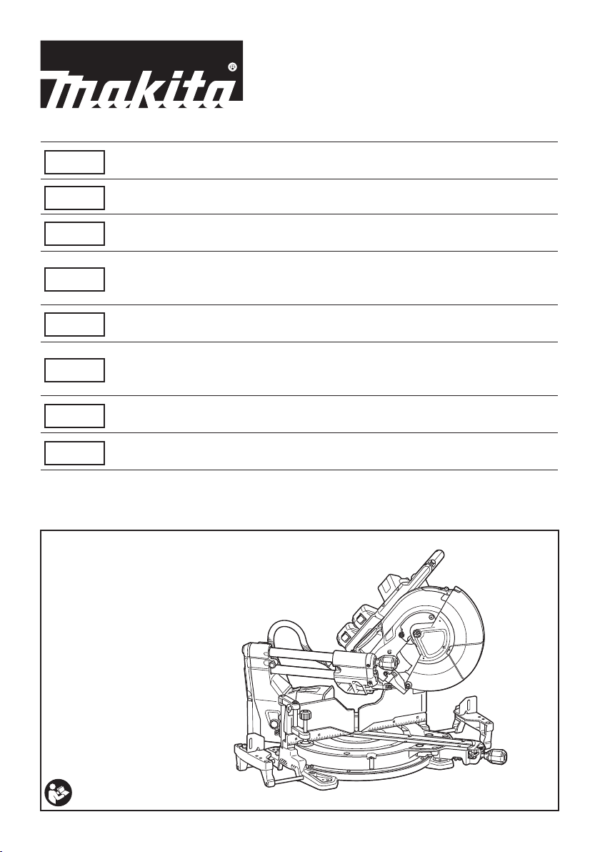
Makita DLS212 User manual

DLS211
DLS212
EN Cordless Slide Compound
Miter Saw INSTRUCTION MANUAL 18
PL Ukośnica Akumulatorowa INSTRUKCJA OBSŁUGI 40
HU Vezeték nélküli csúszókocsis
gérvágó fűrész HASZNÁLATI KÉZIKÖNYV 65
SK
Akumulátorová posuvná
pokosová píla na
kombinované rezanie
NÁVOD NA OBSLUHU 89
CS Akumulátorová radiální
pokosová pila NÁVOD K OBSLUZE 112
UK
Акумуляторна пересувна
комбінована пила для
різання під кутом
ІНСТРУКЦІЯ З
ЕКСПЛУАТАЦІЇ 134
RO Ferăstrău pentru tăieri oblice
combinate, fără cablu MANUAL DE INSTRUCŢIUNI 158
DE Akku-Kapp. und
Gehrungssäge BETRIEBSANLEITUNG 182

Fig.1
17
18
19
20
1
2
3
4
56789
10
11
12
13
14
15
16
21
22 23
Fig.2
2

5
6
79
8
10
10 11 12
13
14
1
2
3
4
15
16
17
18
19
20
21
Fig.3
2
1
Fig.4
1
2
4
3
4
Fig.5
3

1
2
Fig.6
21
3
Fig.7
1
Fig.8
1
3
2
Fig.9
121
Fig.10
1
2
Fig.11
1
Fig.12
4

1
Fig.13
3
1
2
Fig.14
1
Fig.15
1
23
4
6
5
Fig.16
1
Fig.17
1
Fig.18
5

1
32
Fig.19
1
2
Fig.20
1
3
2
4
Fig.21
1
Fig.22
1
Fig.23
6

1
2
Fig.24
1
Fig.25
1
Fig.26
1
Fig.27
3
2
1
Fig.28
3
2
1
Fig.29
1
Fig.30
7

1
Fig.31
A
B
Fig.32
1
Fig.33
3
12
Fig.34
3
1
2
Fig.35
8

1
3
2
4
5
Fig.36
1
2
Fig.37
1 2 345
6
Fig.38
1
3
2
Fig.39
1
2
Fig.40
1
Fig.41
9

12
Fig.42
1
2
4
3
2
1
3
4
Fig.43
2
3
1
Fig.44
1
3
2
4
2
Fig.45
1
2
4
3
Fig.46
12 3
Fig.47
10

2
1
Fig.48
1
2
3
Fig.49
1
Fig.50
1
Fig.51
Fig.52
11

1
2
3
Fig.53
123
Fig.54
2
3
1
4
Fig.55
2
3
4
1
Fig.56
1
3
4
2
Fig.57
1
2
Fig.58
12

1
2
5
3
4
Fig.59
1
2
3
4
Fig.60
2
3
4
1
Fig.61
1
2
34
Fig.62
1
Fig.63
11
23 3
45 54
6
7
Fig.64
Fig.65
13

Fig.66
1
Fig.67
1
3
4
2
Fig.68
3
1
2
Fig.69
1
Fig.70
14

1
2
1
2
Fig.71
Fig.72
1
Fig.73
1
2
Fig.74
1
Fig.75
1
Fig.76
15

1
2
1
2
Fig.77
3
2
1
2
Fig.78
1
Fig.79
1
2
Fig.80
1
2
3
Fig.81
Fig.82
16

1
2
Fig.83
3
4
2
4
1
Fig.84
4
1
2
3
5
Fig.85
5
1
2
3
4
Fig.86
1
2
Fig.87
17

18 ENGLISH
ENGLISH (Original instructions)
SPECIFICATIONS
Model: DLS211 DLS212
Blade diameter European countries 305 mm
Countries other than Europe 305 mm
Hole diameter European countries 30 mm
Countries other than Europe 30 mm or 25.4 mm (country specic)
Max. kerf thickness of the saw blade 3.2 mm
Max. miter angle Right 60°, Left 60°
Max. bevel angle Right 48°, Left 48°
No load speed (RPM) 4,400 min-1
Laser type
Red Laser 650 nm, Maximum output 1.6mW ( Laser Class 2M )
Rated voltage D.C. 36 V
Dimensions (L x W x H) 898 mm x 690 mm x 725 mm
Net weight 30.7 - 31.3 kg
Cutting capacities (H x W)
Miter angle Bevel angle
45° (left) 0° 45° (right)
0° -61 mm x 382 mm
71 mm x 363mm
92 mm x 382 mm
107 mm x 363 mm
44 mm x 382 mm
54 mm x 363 mm
Thickness of wood
facing on guide
fence for increased
height of cut
20 mm 78 mm × 325 mm 115 mm × 325mm 61 mm × 325 mm
38 mm 80 mm × 292 mm 120 mm × 292 mm -
45° (right and left) -61 mm x 268 mm
71 mm x 255 mm
92 mm x 268 mm
107 mm x 255 mm
44 mm x 268 mm
54 mm x 255 mm
Thickness of wood
facing on guide
fence for increased
height of cut
15 mm -115 mm × 227 mm -
25 mm 120 mm × 212 mm
60° (right and left) - - 92 mm x 185 mm
107 mm x 178 mm
-
Thickness of wood
facing on guide
fence for increased
height of cut
15 mm 115 mm × 155 mm
25 mm 120 mm × 140 mm
Cutting capacities for special cuttings
Type of cutting Cutting capacity
Crown molding 45° type
(with crown molding stopper used)
203 mm
Base board
(with horizontal vise used)
171 mm
•
Due to our continuing program of research and development, the specications herein are subject to change without notice.
• Specications may differ from country to country.
• The weight may differ depending on the attachment(s), including the battery cartridge. The lightest and heavi-
est combination, according to EPTA-Procedure 01/2014, are shown in the table.
Applicable battery cartridge and charger
Battery cartridge BL1815N / BL1820 / BL1820B / BL1830 / BL1830B / BL1840 /
BL1840B / BL1850 / BL1850B / BL1860B
Charger DC18RC / DC18RD / DC18RE / DC18SD / DC18SE / DC18SF
•
Some of the battery cartridges and chargers listed above may not be available depending on your region of residence.

19 ENGLISH
WARNING: Only use the battery cartridges and chargers listed above. Use of any other battery cartridges
and chargers may cause injury and/or re.
Symbols
The following show the symbols used for the equip-
ment. Be sure that you understand their meaning before
use.
Read instruction manual.
To avoid injury from ying debris, keep
holding the saw head down, after making
cuts, until the blade has come to a com-
plete stop.
123
When performing bevel cut, rst turn the
knob counterclockwise and then tilt the
carriage. After that, turn the knob clockwise
to tighten.
When performing slide cut, rst pull car-
riage fully and press down handle, then
push carriage toward the guide fence.
Hold down the releasing button when tilting
the carriage to the right.
Engage the stopper lever when cutting a
base board in 45° miter angle.
Do not place hand or ngers close to the
blade.
Never look into the laser beam. Direct laser
beam may injure your eyes.
Do not install the horizontal vise to the
same direction as the miter cutting. (This
symbol is applied on the horizontal vise)
Ni-MH
Li-ion
Only for EU countries
Do not dispose of electric equipment or
battery pack together with household
waste material! In observance of the
European Directives, on Waste Electric
and Electronic Equipment and Batteries
and Accumulators and Waste Batteries and
Accumulators and their implementation
in accordance with national laws, electric
equipment and batteries and battery
pack(s) that have reached the end of
their life must be collected separately and
returned to an environmentally compatible
recycling facility.
Intended use
The tool is intended for accurate straight and miter
cutting in wood. With appropriate saw blades, aluminum
can also be sawed.
Noise
The typical A-weighted noise level determined accord-
ing to EN62841-3-9:
Model DLS211
Sound pressure level (LpA) : 95 dB(A)
Sound power level (LWA) : 103 dB (A)
Uncertainty (K) : 3 dB(A)
Model DLS212
Sound pressure level (LpA) : 95 dB(A)
Sound power level (LWA) : 103 dB (A)
Uncertainty (K) : 3 dB(A)
NOTE:
The declared noise emission value(s) has been
measured in accordance with a standard test method
and may be used for comparing one tool with another.
NOTE:
The declared noise emission value(s) may
also be used in a preliminary assessment of exposure.
WARNING: Wear ear protection.
WARNING: The noise emission during actual
use of the power tool can differ from the declared
value(s) depending on the ways in which the
tool is used especially what kind of workpiece is
processed.
WARNING: Be sure to identify safety mea-
sures to protect the operator that are based on an
estimation of exposure in the actual conditions of
use (taking account of all parts of the operating
cycle such as the times when the tool is switched
off and when it is running idle in addition to the
trigger time).
Vibration
The vibration total value (tri-axial vector sum) deter-
mined according to EN62841-3-9:
Model DLS211
Vibration emission (ah) : 2.5 m/s2or less
Uncertainty (K) : 1.5 m/s2
Model DLS212
Vibration emission (ah) : 2.5 m/s2or less
Uncertainty (K) : 1.5 m/s2
NOTE: The declared vibration total value(s) has been
measured in accordance with a standard test method
and may be used for comparing one tool with another.
NOTE: The declared vibration total value(s) may also
be used in a preliminary assessment of exposure.
WARNING: The vibration emission during
actual use of the power tool can differ from the
declared value(s) depending on the ways in which
the tool is used especially what kind of workpiece
is processed.
WARNING: Be sure to identify safety mea-
sures to protect the operator that are based on an
estimation of exposure in the actual conditions of
use (taking account of all parts of the operating
cycle such as the times when the tool is switched
off and when it is running idle in addition to the
trigger time).
EC Declaration of Conformity
For European countries only
The EC declaration of conformity is included as Annex A
to this instruction manual.

20 ENGLISH
SAFETY WARNINGS
General power tool safety warnings
WARNING: Read all safety warnings, instruc-
tions, illustrations and specications provided
with this power tool. Failure to follow all instructions
listed below may result in electric shock, re and/or
serious injury.
Save all warnings and instruc-
tions for future reference.
The term "power tool" in the warnings refers to your
mains-operated (corded) power tool or battery-operated
(cordless) power tool.
Safety instructions for mitre saws
1. Mitre saws are intended to cut wood or wood-
like products, they cannot be used with abra-
sive cut-off wheels for cutting ferrous material
such as bars, rods, studs, etc. Abrasive dust
causes moving parts such as the lower guard to
jam. Sparks from abrasive cutting will burn the
lower guard, the kerf insert and other plastic parts.
2. Use clamps to support the workpiece when-
ever possible. If supporting the workpiece
by hand, you must always keep your hand at
least 100 mm from either side of the saw blade.
Do not use this saw to cut pieces that are too
small to be securely clamped or held by hand.
If your hand is placed too close to the saw blade,
there is an increased risk of injury from blade
contact.
3. The workpiece must be stationary and
clamped or held against both the fence and the
table. Do not feed the workpiece into the blade
or cut "freehand" in any way. Unrestrained
or moving workpieces could be thrown at high
speeds, causing injury.
4. Push the saw through the workpiece. Do not
pull the saw through the workpiece. To make
a cut, raise the saw head and pull it out over
the workpiece without cutting, start the motor,
press the saw head down and push the saw
through the workpiece. Cutting on the pull stroke
is likely to cause the saw blade to climb on top
of the workpiece and violently throw the blade
assembly towards the operator.
5. Never cross your hand over the intended line
of cutting either in front or behind the saw
blade. Supporting the workpiece "cross handed"
i.e. holding the workpiece to the right of the saw
blade with your left hand or vice versa is very
dangerous.
► Fig.1
6. Do not reach behind the fence with either hand
closer than 100 mm from either side of the saw
blade, to remove wood scraps, or for any other
reason while the blade is spinning. The proxim-
ity of the spinning saw blade to your hand may not
be obvious and you may be seriously injured.
7. Inspect your workpiece before cutting. If the
workpiece is bowed or warped, clamp it with
the outside bowed face toward the fence.
Always make certain that there is no gap
between the workpiece, fence and table along
the line of the cut. Bent or warped workpieces
can twist or shift and may cause binding on the
spinning saw blade while cutting. There should be
no nails or foreign objects in the workpiece.
8. Do not use the saw until the table is clear of all
tools, wood scraps, etc., except for the work-
piece. Small debris or loose pieces of wood or
other objects that contact the revolving blade can
be thrown with high speed.
9.
Cut only one workpiece at a time. Stacked multiple
workpieces cannot be adequately clamped or braced
and may bind on the blade or shift during cutting.
10. Ensure the mitre saw is mounted or placed on
a level, rm work surface before use. A level
and rm work surface reduces the risk of the mitre
saw becoming unstable.
11.
Plan your work. Every time you change the bevel
or mitre angle setting, make sure the adjustable
fence is set correctly to support the workpiece
and will not interfere with the blade or the guard-
ing system. Without turning the tool "ON" and with
no workpiece on the table, move the saw blade
through a complete simulated cut to assure there will
be no interference or danger of cutting the fence.
12. Provide adequate support such as table exten-
sions, saw horses, etc. for a workpiece that is
wider or longer than the table top. Workpieces
longer or wider than the mitre saw table can tip
if not securely supported. If the cut-off piece or
workpiece tips, it can lift the lower guard or be
thrown by the spinning blade.
13.
Do not use another person as a substitute for a
table extension or as additional support. Unstable
support for the workpiece can cause the blade to bind
or the workpiece to shift during the cutting operation
pulling you and the helper into the spinning blade.
14.
The cut-off piece must not be jammed or pressed
by any means against the spinning saw blade. If
conned, i.e. using length stops, the cut-off piece could
get wedged against the blade and thrown violently.
15. Always use a clamp or a xture designed to
properly support round material such as rods
or tubing. Rods have a tendency to roll while
being cut, causing the blade to "bite" and pull the
work with your hand into the blade.
16. Let the blade reach full speed before contact-
ing the workpiece. This will reduce the risk of the
workpiece being thrown.
17. If the workpiece or blade becomes jammed,
turn the mitre saw off. Wait for all moving
parts to stop and disconnect the plug from
the power source and/or remove the battery
pack. Then work to free the jammed material.
Continued sawing with a jammed workpiece could
cause loss of control or damage to the mitre saw.
18. After nishing the cut, release the switch,
hold the saw head down and wait for the blade
to stop before removing the cut-off piece.
Reaching with your hand near the coasting blade
is dangerous.
This manual suits for next models
3
Table of contents
Languages:
Other Makita Saw manuals

Makita
Makita 51778 User manual

Makita
Makita HS7601 User manual

Makita
Makita 5201NA Manual

Makita
Makita JR3050T User manual

Makita
Makita 5057KB User manual

Makita
Makita MLS100 User manual

Makita
Makita DLS713 User manual

Makita
Makita M2401 User manual

Makita
Makita SP001G User manual

Makita
Makita LS1030N Quick start guide

Makita
Makita DJR181 User manual

Makita
Makita 4390D Quick start guide

Makita
Makita DLS211 User manual

Makita
Makita HS0600 User manual

Makita
Makita LS1040F Quick start guide

Makita
Makita 5604R User manual

Makita
Makita SP001G User manual

Makita
Makita LS0816F User manual

Makita
Makita 2414B User manual

Makita
Makita LS0714 Manual