Makita MLT100 User manual

1
GB Table Saw INSTRUCTION MANUAL
UA Розпилювальний верстат ІНСТРУКЦІЯ ЗЕКСПЛУАТАЦІЇ
PL Piła stołowa INSTRUKCJA OBSŁUGI
RO Ferăstrău circular cu masăMANUAL DE INSTRUCŢIUNI
DE Tischkreissäge BEDIENUNGSANLEITUNG
HU Asztali körfűrész HASZNÁLATI KÉZIKÖNYV
SK Stolová píla NÁVOD NA OBSLUHU
CZ Stolní pila NÁVOD K OBSLUZE
MLT100

2
588 mm
1
340 mm
1 009109
1
17 mm
2
2 009108
12
3 006243
1
4 008758
1
2
5 008759
1
6 008760
1
2
7 008761
12
8 008762
(A)
(B)
90
90 45
45
9 006157
1
10 008763
1
2
11 008764
ON OFF
1
2
12 009028
1
13 008765
1
14 008766
1
2
15 008768

3
1
2
16 008767
12
3
17 008769
1
2
3
4
5
18 008770
12
19 008771
12
3
20 008772
1
2
21 008773
12
22 008774
12
23 008775
123
4
5
6
24 008776
1
2
4mm-5mm
25 009201
1
26 008778
1
27 008779
1
28 008780 29 008781
1
2
30 008782

4
120mm
300mm
130mm
50mm
6mm
300mm
130mm
100mm
50mm
9.5mm
50mm
8mm
1
2
34
9.5mm
19mm 120mm
40mm
140mm
460mm
1
1
12
34
42 010130
1
37 008786
1
2
38 008787
1
2
40 008789 41 008790
31 008783
32 006218
33 006210
34 008810 35 008784 36 008785
39 008788

5
43 007834
12
44 006173

6
ENGLISH (Original instructions)
Explanation of general view
1-1. Hole diameter 8 mm
2-1. 6 mm Std. washer
2-2. No.10 wood screw 40 mm min.
length
3-1. 6 mm Std. washer
3-2. 6 mm Mounting bolt & Nut tighten
securely
4-1. Push stick
5-1. Rip fence (Guide rule)
5-2. Miter gauge
6-1. Handle
7-1. Arrow pointer
7-2. Lock lever
8-1. 90 ゚adjusting screw
8-2. 45 ゚adjusting screw
10-1. Arrow pointer
11-1. Switch
11-2. Restart button
12-1. Switch
12-2. Restart button
13-1. Screws
14-1. Sub table (R)
15-1. Screws
15-2. Sub table (back)
16-1. Slide table
16-2. Locking plate
17-1. Wrench
17-2. Wrench
17-3. Hex nut
18-1. Inner flange
18-2. Ring
18-3. Saw blade
18-4. Outer flange
18-5. Hex nut
19-1. Wrench
19-2. Wrench
20-1. Blade guard
20-2. Riving knife
20-3. Blade guard mounting portion
(stay)
21-1. Blade guard
21-2. Riving knife
22-1. Blade guard
22-2. Riving knife
23-1. Blade guard
23-2. Riving knife
24-1. Blade
24-2. These two clearances should be
equal.
24-3. Blade guard mounting portion
(stay)
24-4. Riving knife
24-5. Hex bolts (A)
24-6. Hex bolts (B)
25-1. Blade guard
25-2. Riving knife
26-1. Lever
27-1. Scale
28-1. Hex bolts
30-1. Guideline
30-2. Screw
32-1. Face/edge parallel
32-2. Handle
32-3. Wood screw
32-4. Glue together
33-1. Face/edge parallel
36-1. Push stick
37-1. Auxiliary fence
38-1. Push block
38-2. Auxiliary fence
39-1. Cross cutting
39-2. Mitering
39-3. Bevel cutting
39-4. Compound mitering (angles)
40-1. Miter gauge
40-2. Knob
44-1. Brush holder cap
44-2. Screwdriver
SPECIFICATIONS
MLT100
Model (for European countries) (for other than European countries)
Arbor hole 30 mm 25 mm and 25.4 mm
Blade diameter 260 mm 255 mm
90° 93 mm 90.5 mm
Max. cutting capacities 45° 64 mm 63 mm
No load speed (min-1) 4,300
(685 mm - 835 mm) x (955 mm - 1,305 mm) (685 mm - 835 mm) x (955 mm - 1,305 mm)
Table size (L x W) with sub tables (R) and (back) with sub tables (R) and (back)
726 mm x 984 mm x 333 mm 726 mm x 984 mm x 333 mm
Dimensions (L x W x H) with table(s) not extended with sub tables (R) and (back) with sub tables (R) and (back)
Net weight 34.1 kg 34.1 kg
Safety class ./II
• Due to our continuing programme of research and development, the specifications herein are subject to change without notice.
• Specifications may differ from country to country.
• Weight according to EPTA-Procedure 01/2003
END215-3
Symbols
The following show the symbols used for the equipment.
Be sure that you understand their meaning before use.
・Read instruction manual.
・DOUBLE INSULATION
・Wear safety glasses.
・Do not place hand or fingers close to
the blade.

7
・Only for EU countries
Do not dispose of electric equipment
together with household waste material!
In observance of European Directive
2002/96/EC on waste electric and
electronic equipment and its
implementation in accordance with
national law, electric equipment that
have reached the end of their life must
be collected separately and returned to
an environmentally compatible
recycling facility.
ENE003-1
Intended use
The tool is intended for cutting in wood.
ENF002-1
Power supply
The tool should be connected only to a power supply of
the same voltage as indicated on the nameplate, and
can only be operated on single-phase AC supply. They
are double-insulated in accordance with European
Standard and can, therefore, also be used from sockets
without earth wire.
ENG905-1
Noise
The typical A-weighted noise level determined according
to EN61029:
Sound pressure level (LpA) : 92 dB(A)
Sound power level (LWA) : 105 dB(A)
Uncertainty (K) : 3 dB(A)
Wear ear protection
ENH022-3
For European countries only
EC Declaration of Conformity
We Makita Corporation as the responsible
manufacturer declare that the following Makita
machine(s):
Designation of Machine:
Table Saw
Model No./ Type: MLT100
are of series production and
Conforms to the following European Directives:
2006/42/EC
And are manufactured in accordance with the following
standards or standardised documents:
EN61029
The EC Type-Examination Certificate No.BM 50170011
0001, BM 50170011 0002
The EC Type-Examination was performed by:
TÜV RHEINLAND Product safety GmbH Am
Grauen Stein 51105
Köln, Germany
Identification No. 0197
The technical documentation is kept by our authorised
representative in Europe who is:
Makita International Europe Ltd.
Michigan Drive, Tongwell,
Milton Keynes, Bucks MK15 8JD, England
15.12.2009
000230
Tomoyasu Kato
Director
Makita Corporation
3-11-8, Sumiyoshi-cho,
Anjo, Aichi, 446-8502, JAPAN
GEA010-1
General Power Tool Safety
Warnings
WARNING Read all safety warnings and all
instructions. Failure to follow the warnings and
instructions may result in electric shock, fire and/or
serious injury.
Save all warnings and instructions for
future reference.
ENB095-1
ADDITIONAL SAFETY RULES
FOR TOOL
SAVE THESE INSTRUCTIONS.
1. Wear eye protection.
2. Do not use the tool in presence of flammable
liquids or gases.
3. NEVER use the tool with an abrasive cut-off
wheel installed.
4. Check the blade carefully for cracks or
damage before operation. Replace cracked or
damaged blade immediately.
5. Use only saw blades recommended by the
manufacturer and which conform to EN847-1,
and observe that the riving knife must not be
thicker than the width of the cut by the saw
blade and not thinner than the body of the
blade.
6. Always use accessories recommended in this
manual. Use of improper accessories such as
abrasive cut-off wheels may cause an injury.
7. Select the correct saw blade for the material to
be cut.
8. Do not use saw blades manufactured from
high speed steel.
9. To reduce the emitted noise, always be sure
that the blade is sharp and clean.
10. Use correctly sharpened saw blades. Observe
the maximum speed marked on the saw blade.
11. Clean the spindle, flanges (especially the
installing surface) and hex nut before

8
installing the blade. Poor installation may
cause vibration/wobbling or slippage of the
blade.
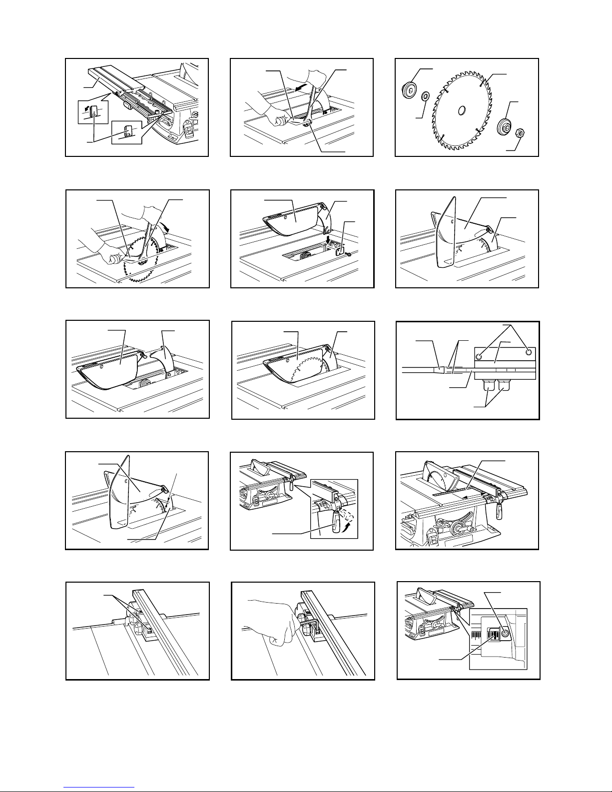
12. Use saw-blade guard and riving knife for every
operation for which it can be used, including
all through sawing operations. Always install
the blade guard following the instructions
out-lined in this manual. Through sawing
operations are those in which the blade cuts
completely through the workpiece as in
ripping or cross cutting. NEVER use the tool
with a faulty blade guard or secure the blade
guard with a rope, string, etc. Any irregular
operation of the blade guard should be
corrected immediately.
13. Immediately reattach the guard and riving
knife after completing an operation which
requires removal of the guard.
14. Do not cut metal objects such as nails and
screws. Inspect for and remove all nails,
screws and other foreign material from the
workpiece before operation.
15. Remove wrenches, cut-off pieces, etc. from
the table before the switch is turned on.
16. NEVER wear gloves during operation.
17. Keep hands out of the line of the saw blade.
18. NEVER stand or permit anyone else to stand in
line with the path of the saw blade.
19. Make sure the blade is not contacting the
riving knife or workpiece before the switch is
turned on.
20. Before using the tool on an actual workpiece,
let it run for a while. Watch for vibration or
wobbling that could indicate poor installation
or a poorly balanced blade.
21. The tool should not be used for slotting,
rabbetting or grooving.
22. Replace table insert when worn.
23. NEVER make any adjustments while tool is
running. Disconnect tool before making any
adjustments.
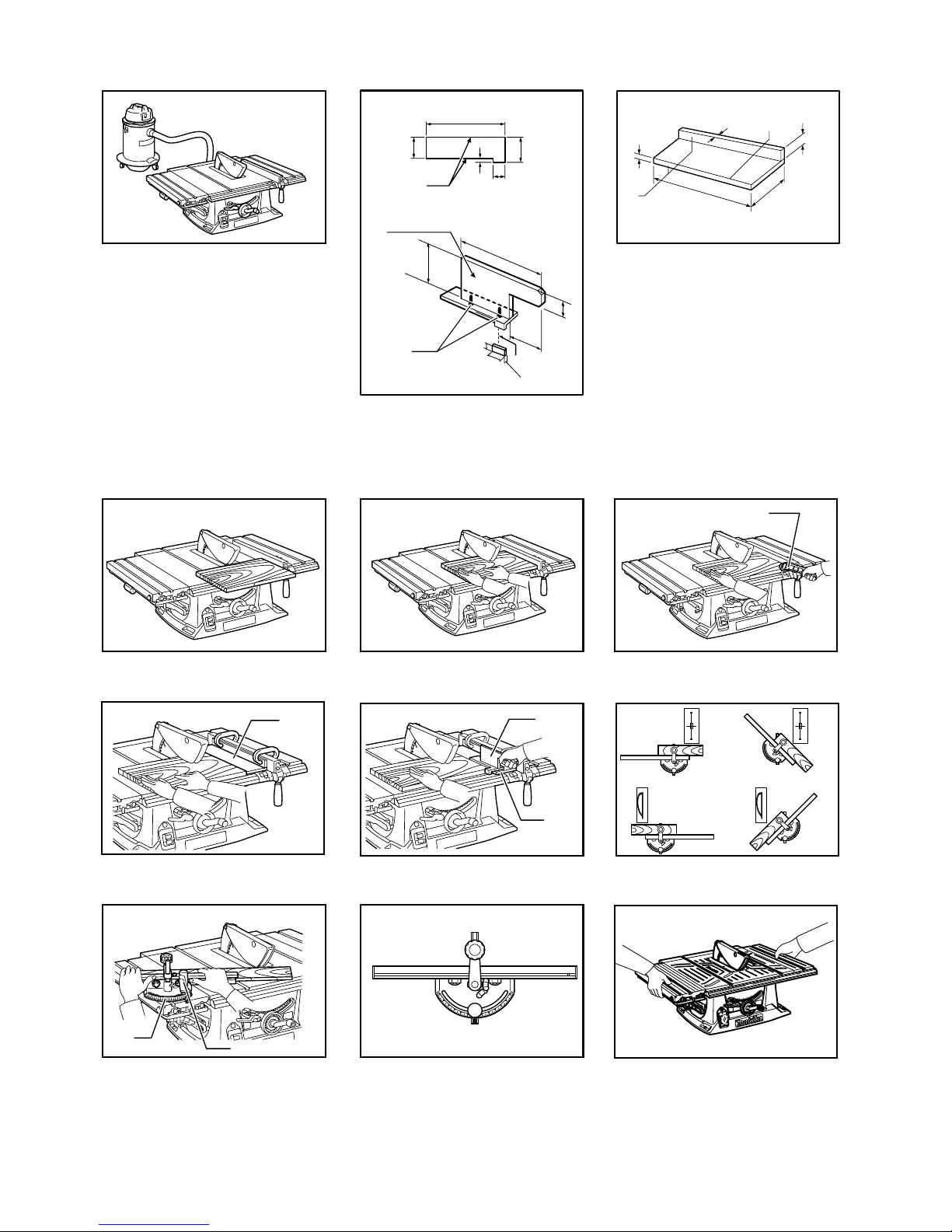
24. Use a push stick when required. Push sticks
MUST be used for ripping narrow workpieces
to keep your hands and fingers well away from
the blade.
25. Always store the push-stick when it is not in
use.
26. Pay particular attention to instructions for
reducing risk of KICKBACK. KICKBACK is a
sudden reaction to a pinched, bound or
misaligned saw blade. KICKBACK causes the
ejection of the workpiece from the tool back
towards the operator. KICKBACKS CAN LEAD
TO SERIOUS PERSONAL INJURY. Avoid
KICKBACKS by keeping the blade sharp, by
keeping the rip fence parallel to the blade, by
keeping the riving knife and blade guard in
place and operating properly, by not releasing
the workpiece until you have pushed it all the
way past the blade, and by not ripping a
workpiece that is twisted or warped or does
not have a straight edge to guide along the
fence.
27. Do not perform any operation freehand.
Freehand means using your hands to support
or guide the workpiece, in lieu of a rip fence or
miter gauge.
28. NEVER reach around or over saw blade.
NEVER reach for a workpiece until the saw
blade has completely stopped.
29. Avoid abrupt, fast feeding. Feed as slowly as
possible when cutting hard workpieces. Do
not bend or twist workpiece while feeding. If
you stall or jam the blade in the workpiece,
turn the tool off immediately. Unplug the tool.
Then clear the jam.
30. NEVER remove cut-off pieces near the blade
or touch the blade guard while the blade is
running.
31. Knock out any loose knots from workpiece
BEFORE beginning to cut.
32. Do not abuse cord. Never yank cord to
disconnect it from the receptacle. Keep cord
away from heat, oil, water and sharp edges.
33. Some dust created from operation contains
chemicals known to cause cancer, birth
defects or other reproductive harm. Some
examples of these chemicals are:
−lead from lead-based-painted material
and,
−arsenic and chromium from
chemically-treated lumber.
−Your risk from these exposures varies,
depending on how often you do this type
of work. To reduce your exposure to these
chemicals: work in a well ventilated area
and work with approved safety equipment,
such as those dust masks that are
specially designed to filter out
microscopic particles.
34. Connect the tool to a dust collecting device
when sawing.
35. The guard can be lifted during workpiece
setup and for ease of cleaning. Always make
sure that guard hood is down and flat against
sawtable before plugging in the tool.
SAVE THESE INSTRUCTIONS.

9
INSTALLATION
Positioning table saw
Fig.1
Fig.2
Fig.3
Locate the table saw in a well lit and level area where
you can maintain good footing and balance. It should be
installed in an area that leaves enough room to easily
handle the size of your workpieces. The table saw
should be secured with four screws or bolts to the work
bench or table saw stand using the holes provided in the
bottom of the table saw. When securing the table saw on
the work bench, make sure that there is an opening in
the top of the work bench the same size as the opening
in the bottom of the table saw so the sawdust can drop
through.
If during operation there is any tendency for the table
saw to tip over, slide or move, the work bench or table
saw stand should be secured to the floor.
Storing accessories
Fig.4
Fig.5
Push stick, Triangular rule, blade and wrenches can be
stored on the left side of the base and the rip fence and
miter gauge can be stored at the right side of the base.
FUNCTIONAL DESCRIPTION
CAUTION:
• Always be sure that the tool is switched off and
unplugged before adjusting or checking function on
the tool.
Adjusting the depth of cut
Fig.6
The depth of cut may be adjusted by turning the handle.
Turn the handle clockwise to raise the blade or
counterclockwise to lower it.
NOTE:
• Use a shallow depth setting when cutting thin
materials in order to obtain a cleaner cut.
Adjusting the bevel angle
Fig.7
Loosen the lock lever counterclockwise and turn the
handwheel until the desired angle (0° - 45°) is obtained.
The bevel angle is indicated by the arrow pointer.
After obtaining the desired angle, tighten the lock lever
clockwise to secure the adjustment.
CAUTION:
• After adjusting the bevel angle, be sure to tighten
the lock lever securely.
Adjusting positive stops
Fig.8
Fig.9
The tool is equipped with positive stops at 90° and 45° to
the table surface. To check and adjust the positive stops,
proceed as follows:
Move the handwheel as far as possible by turning it.
Place a triangular rule on the table and check to see if
the blade is at 90° or 45° to the table surface. If the blade
is at an angle shown in Fig. A, turn the adjusting screws
clockwise; if it is at an angle shown in Fig. B, turn the
adjusting screws counterclockwise to adjust the positive
stops.
After adjusting the positive stops, set the blade at 90° to
the table surface. Then adjust the arrow pointer so that
its right edge is aligned to the 0° graduation.
Fig.10
Switch action
CAUTION:
• Remove workpiece from the table.
• Switch off the tool and then press in the restart
button.
• Before plugging in the tool, always be sure that the
tool is switched off.
For tool with button type switch
Fig.11
To start the tool, press the ON ( I ) button.
To stop it, press the OFF ( O ) button.
For tool with lever type switch
Fig.12
To start the tool, raise the switch lever. To stop it, lower
the switch lever.
Sub table (R)
Fig.13
Fig.14
This tool is provided with the sub table (R) on the right
side of the main table. To use the sub table (R), loosen
two screws on the right side counterclockwise, pull out
the table (R) fully and then tighten the two screws to
secure it.
Sub table (back)
Fig.15
To use the sub table (back), loosen the screws on the left
and right hand sides under the table and pull it out
backwards to the desired length. At the desired length,
tighten the screw securely.
Slide table
Fig.16
CAUTION:
• After using slide table, be sure to lock it by moving
the locking plate to the vertical position.

10
This tool is provided with the slide table on the left side.
The slide table slides back and forth. Pivot the locking
plates on the back and front sides to the horizontal
position before using it.
Hold workpiece firmly with the miter gauge using a
clamp on the miter gauge and slide the workpiece
together with the slide table at the time of cutting
operation.
ASSEMBLY
CAUTION:
• Always be sure that the tool is switched off and
unplugged before carrying out any work on the
tool.
The tool is shipped from the factory with the saw blade
and blade guard not in the installed condition. Assemble
as follows:
Installing or removing saw blade
CAUTION:
• Always be sure that the tool is switched off and
unplugged before installing or removing the blade.
• Use only the Makita socket wrench provided to
install or remove the blade. Failure to do so may
result in overtightening or insufficient tightening of
the hex bolt. This could cause an injury.
• Use the following saw blade. Do not use saw
blades which do not comply with the
characteristics specified in these instructions.
For Model Max. dia. Min. dia. Blade thickness Kerf
MLT100 260mm 230mm 1.8 mm or less 2 mm or more
008811
CAUTION:
• Check the arbor hole diameter of the blade before
installing the blade. Always use the correct ring for
the arbor hole of the blade you intend to use.
Fig.17
Remove the table insert on the table. Hold the outer
flange with the wrench and loosen the hex nut
counterclockwise with the wrench. Then remove the
outer flange.
Fig.18
Assemble the inner flange, ring, saw blade, outer flange
and hex nut onto the arbor, making sure that the teeth of
the blade are pointing down at the front of the table.
Always install the hex nut with its recessed side facing
the outer flange.
For all countries other than European countries
CAUTION:
• The ring 25.4 mm in outer diameter is
factory-installed onto the spindle.
For European countries
CAUTION:
• The ring 30 mm in outer diameter is
factory-installed between the inner and outer
flanges.
• Keep the flange surface clean of dirt or other
adhering matter; it could cause blade slippage. Be
sure that the blade is installed so that the teeth are
aligned in the cutting (turning) direction.
To secure the blade in place, hold the outer flange with
the offset wrench, then tighten the hex nut clockwise
with the wrench. BE SURE TO TIGHTEN THE HEX NUT
SECURELY.
Fig.19
CAUTION:
• Be sure to hold the hex nut carefully with the
wrench. If your grip should slip, the wrench may
come off the hex nut, and your hand could strike
the sharp blade edges.
Installing blade guard
Fig.20
Fig.21
CAUTION:
• Before installing the blade guard, adjust the depth
of cut to its maximum elevation.
For non-European type blade guard
Remove the center cover. Insert the riving knife into the
blade guard mounting portion (stay). Tighten the hex
bolts (A) with the provided wrench.
For European type blade guard
Fig.22
Fig.23
Remove the center cover. Insert the riving knife into the
blade guard mounting portion (stay). Tighten the hex
bolts (A) with the provided wrench.
Place the blade guard into the groove on the riving knife.
Secure the blade guard by pivoting the lever on the
blade guard.
For both European and non-European type blade
guards
The riving knife installing location is factory-adjusted so
that the blade and riving knife will be in a straight line.
However, if they are not in a straight line, loosen the hex
bolts (B) and adjust the blade guard mounting portion
(stay) so that the riving knife is aligned directly behind
the blade. Then tighten the hex bolts (B) to secure the
stay.
Fig.24
CAUTION:
• If the blade and riving knife are not aligned properly,
a dangerous pinching condition may result during
operation. Make sure they are properly aligned.
You could suffer serious personal injury while using
the tool without a properly aligned riving knife.

11
• NEVER make any adjustments while tool is
running. Disconnect the tool before making any
adjustments.
• Don't remove the riving knife.
Fig.25
There must be a clearance of about 4 - 5 mm between
the riving knife and the blade teeth. Loosen the hex bolts
(A) and adjust the riving knife accordingly and tighten
the hex bolts (A) securely. Attach the table insert on the
table, then check to see that the blade guard works
smoothly before cutting.
Installing and adjusting rip fence
Fig.26
Install the rip fence so that the fence holder engages
with the nearmost guide rail.
To secure the rip fence, pivot fully the lever on the fence
holder.
To check to be sure that the rip fence is parallel with the
blade, secure the rip fence 2 - 3 mm from the blade.
Raise the blade up to maximum elevation. Mark one of
the blade teeth with a crayon. Measure the distance (A)
and (B) between the rip fence and blade. Take both
measurements using the tooth marked with the crayon.
These two measurements should be identical. If the rip
fence is not parallel with the blade, proceed as follows:
Fig.27
Fig.28
1. Secure the rip fence by lowering the lever on it.
2. Loosen the two hex bolts on the rip fence with the
hex wrench provided.
3. Adjust the rip fence until it becomes parallel with
the blade.
4. Tighten the two hex bolts on the rip fence.
Fig.29
CAUTION:
• Be sure to adjust the rip fence so that it is parallel
with the blade, or a dangerous kickback condition
may occur.
Bring the rip fence up flush against the side of the blade.
Make sure that the guideline on the fence holder points
to the 0 graduation. If the guideline does not point to the
0 graduation, loosen the screw on the scale plate and
adjust the scale plate.
Fig.30
Connecting to vacuum cleaner
Fig.31
Cleaner operations can be performed by connecting the
tool to Makita vacuum cleaner or dust collector.
OPERATION
CAUTION:
• Always use "work helpers" such as push sticks and
push blocks when there is a danger that your
hands or fingers will come close to the blade.
• Always hold the workpiece firmly with the table and
the rip fence or miter gauge. Do not bend or twist it
while feeding. If the workpiece is bent or twisted,
dangerous kickbacks may occur.
• NEVER withdraw the workpiece while the blade is
running. If you must withdraw the workpiece before
completing a cut, first switch the tool off while
holding the workpiece firmly. Wait until the blade
has come to a complete stop before withdrawing
the workpiece. Failure to do so may cause
dangerous kickbacks.
• NEVER remove cut-off material while the blade is
running.
• NEVER place your hands or fingers in the path of
the saw blade. Be especially careful with bevel
cuts.
• Always secure the rip fence firmly, or dangerous
kickbacks may occur.
• Always use "work helpers" such as push sticks and
push blocks when cutting small or narrow
workpieces.
Work helpers
Push sticks, push blocks or auxiliary fence are types of
"work helpers". Use them to make safe, sure cuts
without the need for the operator to contact the blade
with any part of the body.
Push block
Fig.32
Use a 19 mm piece of plywood.
Handle should be in center of plywood piece. Fasten
with glue and wood screws as shown. Small piece 9.5
mm x 8 mm x 50 mm of wood must always be glued to
plywood to keep the blade from dulling if the operator
cuts into push block by mistake. (Never use nails in push
block.)
Auxiliary fence
Fig.33
Make auxiliary fence from 9.5 mm and 19 mm plywood
pieces.
Ripping
CAUTION:
• When ripping, remove the miter gauge from the
table.
• When cutting long or large workpieces, always
provide adequate support behind the table. DO
NOT allow a long board to move or shift on the
table. This will cause the blade to bind and
increase the possibility of kickback and personal
injury. The support should be at the same height as
the table.
1. Adjust the depth of cut a bit higher than the
thickness of the workpiece.

12
Fig.34
2. Position the rip fence to the desired width of rip
and lock in place by pivoting the grip.
3. Turn the tool on and gently feed the workpiece
into the blade along with the rip fence.
(1) When the width of rip is 150 mm and wider,
carefully use your right hand to feed the
workpiece. Use your left hand to hold the
workpiece in position against the rip fence.
Fig.35
(2) When the width of rip is 65 mm - 150 mm
wide, use the push stick to feed the
workpiece.
Fig.36
(3) When the width of rip is narrower than 65 mm,
the push stick cannot be used because the
push stick will strike the blade guard. Use the
auxiliary fence and push block. Attach the
auxiliary fence to the rip fence with two "C"
clamps.
Fig.37
Feed the workpiece by hand until the end is
about 25 mm from the front edge of the table.
Continue to feed using the push block on the
top of the auxiliary fence until the cut is
complete.
Fig.38
Cross cutting
CAUTION:
• When making a crosscut, remove the rip fence
from the table.
• When cutting long or large workpieces, always
provide adequate support to the sides of the table.
The support should be at the same height as the
table.
• Always keep hands away from path of blade.
Miter gauge
Fig.39
Use the miter gauge for the 4 types of cutting shown in
the figure.
CAUTION:
• Secure the knob on the miter gauge carefully.
• Avoid creep of workpiece and gauge by firm
workholding arrangement, especially when cutting
at an angle.
• NEVER hold or grasp the intended "cut-off" portion
of the workpiece.
• Always adjust the distance between the end of the
miter gauge and the saw blade not to exceed 15
mm.
Use of miter gauge
Fig.40
Slide the miter gauge into the thick grooves in the table.
Loosen the knob on the gauge and align to desired
angle (0° to 60°). Bring stock flush up against fence and
slide table, secure it with the clamp on the miter gauge
and feed gently forward into the blade.
Auxiliary wood facing (miter gauge)
Fig.41
To prevent a long board from wobbling, fit the miter
gauge with an auxiliary fence board. Fasten with
bolts/nuts after drilling holes, but fasteners must not
protrude from the face board.
Carrying tool
Fig.42
Make sure that the tool is unplugged.
Carry the tool by holding the tool part shown in the
figure.
CAUTION:
• Always secure all moving portions before carrying
the tool.
• Always make sure that the blade guard is installed
in place before the carrying the tool.
MAINTENANCE
CAUTION:
• Always be sure that the tool is switched off and
unplugged before attempting to perform inspection
or maintenance.
NOTICE:
• Never use gasoline, benzine, thinner, alcohol or
the like. Discoloration, deformation or cracks may
result.
Cleaning
Clean out sawdust and chips from time to time. Carefully
clean the blade guard and moving parts inside the table
saw.
Lubrication
To keep the table saw in tip-top running condition, and to
assure maximum service life, oil or grease the moving
parts and rotating parts from time to time.
Lubrication places:
• Threaded shaft to elevate the blade
• Hinge to rotate the frame
• Elevation guide shafts on motor
• Gear to elevate the blade
Replacing carbon brushes
Fig.43
Remove and check the carbon brushes regularly.
Replace when they wear down to 3 mm in length. Keep
the carbon brushes clean and free to slip in the holders.
Both carbon brushes should be replaced at the same
time. Use only identical carbon brushes.
Fig.44
Use a screwdriver to remove the brush holder caps. To
replace the carbon brushes, remove the blade guard

13
and blade and then loosen the lock lever, tilt the saw
head and secure it at 45° bevel angle. Carefully lay the
tool on itself backward. Then loosen the brush holder
cap. Remove the worn carbon brushes, insert the new
ones and secure the brush holder caps.
To maintain product SAFETY and RELIABILITY, repairs,
any other maintenance or adjustment should be
performed by Makita Authorized Service Centers,
always using Makita replacement parts.
ACCESSORIES
CAUTION:
• These accessories or attachments are
recommended for use with your Makita tool
specified in this manual. The use of any other
accessories or attachments might present a risk of
injury to persons. Only use accessory or
attachment for its stated purpose.
If you need any assistance for more details regarding
these accessories, ask your local Makita Service Center.
• Rip fence
• Miter gauge
• Wrench 24
• Hex wrench 5
• Joint ( for connecting to dust collector )
• Stand set

14
УКРАЇНСЬКА (Оригінальні інструкції)
Пояснення до загального виду
1-1. Діаметр отвору 8 мм
2-1. Стандартна шайба 6 мм
2-2. Гвинт для деревини №10
довжиною 40 мм
3-1. Стандартна шайба 6 мм
3-2. Установочний болт 6 мм та гайка,
надійно затягніть
4-1. Штовхач
5-1. Напрямна планка (реєстрова
мітка)
5-2. Кутовий шаблон
6-1. Ручка
7-1. Стрілочний покажчик
7-2. Стопорний важіль
8-1. регулювальний гвинт, що
повертається до 90 ゚
8-2. регулювальний гвинт, що
повертається до 45 ゚
10-1. Стрілочний покажчик
11-1. Перемикач
11-2. Кнопка перезапуску
12-1. Перемикач
12-2. Кнопка перезапуску
13-1. Гвинти
14-1. Допоміжний стіл (R)
15-1. Гвинти
15-2. Допоміжний стіл (задній)
16-1. Рухомий стіл
16-2. Планка блокування
17-1. Ключ
17-2. Ключ
17-3. Шестигранна гайка
18-1. Внутрішній фланець
18-2. Кільце
18-3. Диск пили
18-4. Зовнішній фланець
18-5. Шестигранна гайка
19-1. Ключ
19-2. Ключ
20-1. Кожух полотна
20-2. Запобіжний ніж
20-3. частина встановлення кожуха
полотна (розпірка)
21-1. Кожух полотна
21-2. Запобіжний ніж
22-1. Кожух полотна
22-2. Запобіжний ніж
23-1. Кожух полотна
23-2. Запобіжний ніж
24-1. Полотно
24-2. Ці два зазори повинні бути
рівними.
24-3. частина встановлення кожуха
полотна (розпірка)
24-4. Запобіжний ніж
24-5. Болти із шестигранними
голівками (А)
24-6. Болти із шестигранними
голівками (В)
25-1. Кожух полотна
25-2. Запобіжний ніж
26-1. Важіль
27-1. Масштаб
28-1. Болти із шестигранною голівкою
30-1. Напрямна лінія
30-2. Гвинт
32-1. Паралель поверхні/краю
32-2. Ручка
32-3. Шуруп
32-4. Склеювання
33-1. Паралель поверхні/краю
36-1. Штовхач
37-1. Додаткова огорожа
38-1. Блок штовхача
38-2. Додаткова огорожа
39-1. ПОПЕРЕЧНЕ РІЗАННЯ
39-2. КОСЕ РІЗАННЯ
39-3. РІЗАННЯ ПІД КУТОМ
39-4. ГРУПОВЕ КОСЕ РІЗАННЯ
(КУТИ)
40-1. Кутовий шаблон
40-2. Ручка
44-1. Ковпачок щіткотримача
44-2. Викрутка
ТЕХНІЧНІ ХАРАКТЕРИСТИКИ
MLT100
Модель (для європейських країн) (для неєвропейських країн)
Отвір шпинделя 30 мм 25 мм та 25,4 мм
Діаметр диску 260 мм 255 мм
90° 93 мм 90,5 мм
Макс. ріжуча
спроможність 45° 64 мм 63 мм
Швидкість холостого ходу (хв.-1) 4300
(685 мм - 835 мм) x (955 мм - 1305 мм) (685 мм - 835 мм) x (955 мм - 1305 мм)
Розмір стола (ДхШ)
із допоміжними столами (R) та (задній)із допоміжними столами (R) та (задній)
726 мм x 984 мм x 333 мм 726 мм x 984 мм x 333 мм
Розміри (ДхШхВ) зне розкладеними столами
із допоміжними столами (R) та (задній)із допоміжними столами (R) та (задній)
Чиста вага 34,1 кг 34,1 кг
Клас безпеки ./II
• Через те, що ми не припиняємо програми досліджень ірозвитку, наведені тут технічні характеристики можуть бути змінені
без попередження.
• Урізних країнах технічні характеристики можуть бути різними.
• Вага відповідно до EPTA-Procedure 01/2003

15
END215-3
Символи
Далі наведені символи, які застосовуються для
позначення обладнання. Перед користуванням
переконайтеся, що Ви розумієте їхнє значення.
・Прочитайте дану інструкцію.
・ПОДВІЙНА ІЗОЛЯЦІЯ
・Одягай захисні окуляри.
・Тримай руки або пальці на відстані
від диску.
・Тільки для країн ЄС
Не викидайте електричне
обладнання разом зпобутовим
сміттям!
Відповідно до Європейської
директиви 2002/96/EC про утилізацію
електричного та електронного
обладнання та її застосуванням
згідно знормами національного
законодавства, електрообладнання,
яке вийшло зладу, необхідно збирати
окремо та відправляти на переробне
підприємство, яке відповідає вимогам
охорони довкілля.
ENE003-1
Призначення
Інструмент призначено для різання деревини.
ENF002-1
Джерело живлення
Інструмент можна підключати лише до джерела
струму, що має напругу, зазначену втабличці з
заводськими характеристиками, івін може
працювати лише від однофазного джерела
перемінного струму. Інструмент має подвійну
ізоляцію згідно зєвропейським стандартом і, отже,
може підключатися до розеток без клеми
заземлення.
ENG905-1
Шум
Рівень шуму за шкалою Аутиповому виконанні,
визначений відповідно до EN61029:
Рівень звукового тиску (LpA): 92 дБ(A)
Рівень акустичної потужності (LWA): 105 дБ(A)
Похибка (K) : 3 дБ(A)
Користуйтеся засобами захисту слуху
ENH022-3
Тільки для країн Європи
Декларація про відповідність стандартам
ЄС
Наша компанія, Makita Corporation, як
відповідальний виробник, наголошує на тому, що
обладнання Makita:
Позначення обладнання:
Розпилювальний верстат
№моделі / тип: MLT100
єсерійним виробництвом та
Відповідає таким Європейським Директивам:
2006/42/EC
Та вироблені увідповідності до таких стандартів та
стандартизованих документів:
EN61029
№сертифіката ЄС на проведення типових
випробувань.BM 50170011 0001, BM 50170011 0002
Типові випробування на відповідність вимогам
ЄС були проведені:
TÜV RHEINLAND Product safety GmbH Am
Grauen Stein 51105
Köln, Germany
Ідентифікаційний №0197
Технічна документація знаходиться унашого
уповноваженого представника вЄвропі, асаме:
Makita International Europe Ltd.
Michigan Drive, Tongwell,
Milton Keynes, Bucks MK15 8JD, Англія
15.12.2009
000230
Tomoyasu Kato
Директор
Makita Corporation
3-11-8, Sumiyoshi-cho,
Anjo, Aichi, 446-8502, ЯПОНІЯ
GEA010-1
Застереження стосовно техніки
безпеки при роботі з
електроприладами
УВАГА! Прочитайте усі застереження
стосовно техніки безпеки та всі інструкції.
Недотримання даних застережень та інструкцій може
призвести до ураження струмом та виникнення
пожежі та/або серйозних травм.
Збережіть усі інструкції зтехніки
безпеки та експлуатації на майбутнє.
ENB095-1
ДОДАТКОВІ ПРАВИЛА
БЕЗПЕКИ ПРИ КОРИСТУВАННІ
ІНСТРУМЕНТОМ
ЗБЕРІГАЙТЕ ЦІ ВКАЗІВКИ
1. Одягайте захисні окуляри
2. Не слід користуватися інструментом при
наявності займистих рідин та газів.

16
3. Забороняється встановлювати абразивне
відрізне коло на інструмент та
користуватися ним.
4. Перед початком роботи слід ретельно
перевірити полотно на наявність тріщин
або пошкодження. Слід негайно замінити
тріснуте або пошкоджене полотно.
5. Слід користуватися тільки пильними
дисками, що рекомендовані виробником та
які відповідають EN847-1, та товщина
запобіжного ножа не повинна бути більше
ширини прорізу від пильного диску та менш
полотна диску.
6. Завжди використовуй приналежності
рекомендовані вцій інструкції.
Використання неналежного приладдя,
наприклад абразивних відрізних кіл, може
призвести до поранення..
7. Обирайте пильний диск відповідно до
матеріалу, що буде різатися
8. Не слід застосовувати диски пилки, що
виготовлені зшвидкорізальної сталі
9. Для того, щоб зменшити вироблений шум,
диск повинен бути завжди гострим та
чистим.
10. Слід використовувати правильно
загострені диски пилки. Дотримуйтесь
максимальної швидкості зазначеної на
диску пилки.
11. Перед встановленням диску слід почистити
шпиндель, фланці (особливо поверхню
встановлення) та шестигранну гайку.
Неправильне встановлення може
призвести до вібрації/коливання або
прослизання диску.
12. Слід користуватися кожухом пильного
диску та запобіжним ножем кожного разу
коли це можливо, утому числі під час
наскрізного різання. Захисний кожух диску
слід обов'язково встановлювати згідно до
інструкцій, зазначених уцьому посібнику.
Наскрізне різання відбувається коли диск
прорізає наскрізь деталь як під час
поздовжнього, так іпоперечного різання.
ЗАБОРОНЯЄТЬСЯ користуватися
інструментом із несправним захисним
кожухом диску або кріпити кожух за
допомогою мотузки, струни іт.д. Слід
негайно скорегувати захисний кожух уразі
його неправильного функціонування.
13. Обов'язково слід встановити захисний
кожух та запобіжний ніж знову після
завершення роботи, яка потребує зняття
кожуху.
14. Забороняється різати металеві предмети, а
саме цвяхи та гвинти. Перед початком
роботи огляньте деталь та заберіть усі
цвяхи, гвинти та інший сторонній матеріал з
деталі.
15. Перед увімкненням заберіть ключі, відрізки
іт.д. зі столу.
16. НІКОЛИ не одягайте рукавиць під час
роботи.
17. Не тримай руки на лінії пильного диску.
18. ЗАБОРОНЯЄТЬСЯ стояти або дозволяти
комусь ще стояти на одній лінії зі шляхом
пильного диску.
19. Перед увімкненням перевірте, щоб полотно
не торкалося запобіжного ножа або деталі.
20. Перед використанням інструменту на
фактичній деталі, залиште його якийсь час
на холостому ході. Зверніть увагу на
вібрацію та колихання, що вказують на
погане встановлення або балансування
диску.
21. Інструмент не слід застосовувати для
прорізання отворів, випилювання жолобків
або пазів.
22. Слід замінити вкладиш столу уразі його
зношування.
23. ЗАБОРОНЕНО виконувати будь-які
регулювання під час роботи інструмента.
Перед регулюванням слід відключити
інструмент.
24. Користуйся штовхачем при необхідності.
Штовхачі СЛІД використовувати для
поздовжнього різання вузьких деталей для
того, щоб тримати руки та пальці на
відстані від диску.
25. Зберігай штовхач, коли не користуєшся
ним.
26. Особливу увагу слід приділити інструкціям
зі зменшення ризику ВІДДАЧІ. ВІДДАЧА це
несподівана реакція защемленого,
застряглого або зміщеного пильного диску.
ВІДДАЧА спричиняє відстрілювання деталі
зінструменту до оператора. ВІДДАЧА
МОЖЕ ПРИЗВЕСТИ ДО СЕРЙОЗНОГО
ПОРАНЕННЯ Для того, щоб уникнути
ВІДДАЧУ, полотно повинно бути завжди
гострим, напрямна планка повинна бути
встановлена паралельно полотна,
запобіжний ніж та захисний кожух диску
повинні бути вробочому положенні та у
працездатному стані, не слід відпускати
деталь доки вона не буде вштовхнута
повністю до полотна, та не слід різати
уздовж скручену або згорнуту деталь або
при відсутності трикутника для
спрямування уздовж планки.
27. Не слід здійснювати різання "зруки" "З
руки" означає, що замість використання
напрямної планки або кутового шаблону, ви
підтримуєте або спрямовуєте деталь
своїми руками.

17
28. НІКОЛИ не слід обхоплювати пильний диск.
НІКОЛИ не слід тягнутися до деталі доки
пильний диск повністю не зупиниться.
29. Слід уникати різкої, швидкої подачі. Під час
різання твердих деталей подавайте їх як
можна повільніше. Забороняється гнути
або скручувати деталь при подачі. Якщо
полотно заклинило або защемилося в
деталі, негайно вимкніть інструмент.
Виключіть інструмент із сіті. Потім слід
усунути защемлення.
30. ЗАБОРОНЯЄТЬСЯ забирати відрізки біля
диску або торкатися кожуха диску під час
роботи диску.
31. ПЕРЕД початком різання сліди вибити
послаблені капи із деталі.
32. Не пошкоджуйте шнур. Ніколи не смикайте
шнур, щоб витягти його із розетки. Тримай
шнур на відстані від джерела тепла, мастил,
води та гострих країв.
33. Інколи пил, що утворюється під час різання,
містить хімічні речовини, які спричиняють
захворювання на рак, пороки розвитку або
інші репродуктивні шкоди. Нижче наведені
деякі зцих хімічних речовин:
−свинець, який утворюється під час
різання матеріалу збарвником на
свинцевій основі, атакож,
−Миш'як та хром, які утворюються під
час різання хімічно обробленого
пиломатеріалу.
−Ризик впливу таких речовин залежить
від частоти виконання вами такого виду
роботи. Для того, щоб зменшити вплив
таких хімічних речовин: слід працювати
вдобре провітрюваному приміщенні та
із затвердженими засобами
індивідуального захисту, такими як
пилозахисні маски, які спеціально
призначені для фільтрації
мікроскопічних часток.
34. Під час різання слід приєднати пристрій
для збору пилу до інструменту.
35. Можна підіймати захисний кожух під час
встановлення деталі та для полегшення
чистки. Перед увімкненням інструменту до
мережі слід завжди перевіряти, щоб ковпак
кожуху був опущений на площині пильного
столу.
ЗБЕРІГАЙТЕ ЦІ ВКАЗІВКИ
ВСТАНОВЛЕННЯ
Встановлення розпилювального верстата
Fig.1
Fig.2
Fig.3
Розпилювальний верстат слід розміщувати вмісці,
що добре освітлюється, та де можна твердо та стійко
стояти на ногах. Його слід встановлювати на ділянці,
де єдостатньо місця для того, щоб можне було
вільно пересувати деталі відповідного розміру.
Розпилювальна машина повинна бути прикріплена за
допомогою двох гвинтів або болтів до верстату або
стійки для розпилювального верстата через отвори,
розташовані внижній частині розпилювального
верстата. Під час закріплення розпилювального
верстата на стенді слід перевірити, щоб отвір у
верхній частині стенда був того жрозміру, що йотвір
внижній частині розпилювального верстата, щоб
через нього випадала тирса.
Якщо під час експлуатації з'являється тенденція до
перевертання, сповзання або руху розпилювального
верстата, то стенд або стійка розпилювального
верстата повинен бути прикріплений до полу.
Зберігання приналежностей
Fig.4
Fig.5
Направляючу лінійку, трикутну лінійку, полотна та
ключі можна зберігати злівого боку основи, а
напрямну планку ікутовий шаблон можна зберігати з
правого боку основи.
ІНСТРУКЦІЯ ЗВИКОРИСТАННЯ
ОБЕРЕЖНО:
• Перед регулюванням та перевіркою справності
інструменту, переконайтеся втому, що він
вимкнений та відключений від мережі.
Порядок регулювання глибини різання
Fig.6
Глибину різання можна регулювати шляхом
повертання ручки. Поверніть ручку по годинниковій
стрілці, щоб підняти полотно, та проти годинникової
стрілки - щоб опустити.
ПРИМІТКА:
• Для різання тонких деталей або для чистішого
різання слід використовувати малу глибину
різання.
Регулювання кута нахилу
Fig.7
Послабте важіль блокування проти часової стрілки та
поверніть маховик на необхідний кут (0° - 45°). Кут
нахилу вказується стрілочним покажчиком.

18
Після отримання необхідного кута слід затягнути
важіль блокування по годинниковій стрілці для того,
щоб закріпити відрегульовану величину.
ОБЕРЕЖНО:
• Після регулювання кута нахилу слід перевірити,
щоб важіль блокування був надійно затягнутий.
Регулювання упорів-обмежувачів
Fig.8
Fig.9
Верстат обладнаний упорами-обмежувачами під 90°
та 45° відносно поверхні столу. Для перевірки та
регулювання упорів-обмежувачів слід виконати
наступну процедуру:
Пересуньте маховик якомога дальше, повертаючи
його. Встановіть трикутну лінійку на стіл та перевірте,
чи знаходиться полотно під 90° або 45° до поверхні
столу. Якщо полотно розташоване під кутом, що
вказаний на мал. F, то слід повернути гвинти
регулювання по годинниковій стрілці; якщо воно
розташоване під кутом, що вказаний на мал. В, слід
повернути гвинти регулювання проти годинникової
стрілки, щоб відрегулювати упори-обмежувачі.
Після регулювання упорів-обмежувачів слід
встановити полотно під 90° до поверхні. Потім
відрегулюйте стрілочний покажчик так, щоб його
правий край був суміщений зподілкою 0°.
Fig.10
Дія вимикача.
ОБЕРЕЖНО:
• Зніміть деталь зі столу.
• Відключіть інструмент інатисніть кнопку
перезавантаження.
• Перед включенням інструменту до мережі, слід
завжди перевіряти, щоб інструмент був
вимкнений.
Для інструмента зперемикачем кнопкового типу
Fig.11
Для того, щоб запустити верстат, слід натиснути на
кнопку ВМК. (І).
Для того, щоб зупинити верстат, слід натиснути на
кнопку ВИМК. (О).
Для інструмента зперемикачем важільного типу
Fig.12
Для того, щоб запустити верстат, підніміть важіль
перемикача. Для зупинки слід опустити важіль
перемикача.
Допоміжний стіл (R)
Fig.13
Fig.14
Інструмент обладнаний допоміжним столом (R) з
правого боку від основного стола. Для використання
допоміжного стола (R) слід послабити два гвинти з
правого боку, повертаючи їх проти годинникової
стрілки, повністю витягнути стіл (R), апотім затягнути
гвинти для того, щоб його закріпити.
Допоміжний стіл (задній)
Fig.15
Для використання допоміжного стола (заднього)
потрібно послабити гвинти злівого іправого боку під
столом та витягнути його назад на необхідну довжину.
Досягнувши необхідної довжини гвинт потрібно
надійно затягнути.
Рухомий стіл
Fig.16
ОБЕРЕЖНО:
• Після використання рухомого столу обов’язково
заблокуйте його, перемістивши планку
блокування увертикальне положення.
Інструмент обладнаний пересувним столом злівого
боку. Пересувний стіл пересувається вперед іназад.
Перед використанням поверніть передню ізадню
планки блокування вгоризотальне положення.
Міцно затисніть деталь зкутовим шаблоном за
допомогою фіксатора кутового шаблона і
переміщуйте деталь разом із рухомим столом під час
процесу різання.
КОМПЛЕКТУВАННЯ
ОБЕРЕЖНО:
• Перед тим, як зайнятись комплектуванням
інструменту, переконайтеся втому, що він
вимкнений та відключений від мережі.
Верстат поставляється із заводу без встановленого
полотна та кожуха полотна. Збирати їх слід
наступним чином:
Встановлення та зняття полотна пили
ОБЕРЕЖНО:
• Завжди перевіряйте, щоб верстат був
вимкнений та відключений від сіті перед
встановленням або зняттям полотна.
• Для встановлення або зняття полотна слід
використовувати тільки торцевий ключ
виробництва компанії Makita, що додається.
Якщо цю вимогу не виконати, то болт із
шестигранною голівкою може бути затягнутий
або занадто сильно, або недостатньо. Це може
призвести до поранень.
• Використовуйте наступні полотна. Неможна
використовувати полотна для пили, які не
відповідають характеристикам, що наведені в
цій інструкції.
Для моделі
Макс. діаметр
Мін. діаметр
Товщина леза Западина
MLT100 260 мм 230 мм
1,8 мм або менше 2 мм або більше
008811

19
ОБЕРЕЖНО:
• Перевірте діаметр отвору шпинделя полотна
перед тим, як встановлювати полотно. Для
полотна, яке ви збираєтесь використовувати,
слід завжди використовувати відповідне кільце
для діаметр отвору шпинделя.
Fig.17
Зніміть вставку зі столу. Утримуйте зовнішній
фланець за допомогою ключа та послабте
шестигранну гайку проти годинникової стрілки за
допомогою ключа. Потім зніміть зовнішній фланець.
Fig.18
Змонтуйте внутрішній фланець, кільце, полотно,
зовнішній фланець та шестигранну гайку на
шпинделі, перевіривши, щоб зубці полотна були
направлені вниз на передній частині столу. Слід
завжди встановлювати шестигранну гайку
поглибленою частиною до фланця.
Для всіх країн крім Європейських
ОБЕРЕЖНО:
• Кільце зовнішнім діаметром 25,4 мм
встановлюється на шпиндель на заводі
Для Європейських країн
ОБЕРЕЖНО:
• Кільце зовнішнім діаметром 30 мм
встановлюється на заводі між внутрішнім та
зовнішнім фланцями.
• Поверхню фланця слід тримати очищеною від
бруду та інших матеріалів, що пристають,
оскільки це може визвати прослизання полотна.
Перевірте, щоб полотно було встановлене
таким чином, щоб його зубці були суміщені із
напрямом різання (обертання).
Для того, щоб закріпити полотно, слід утримувати
зовнішній фланець за допомогою колінчастого ключа
та затягнути по годинниковій стрілці ключем
шестигранну гайку. ПЕРЕВІРТЕ, ЩОБ
ШЕСТИГРАННА ГАЙКА БУЛА НАДІЙНО ЗАТЯГНУТА.
Fig.19
ОБЕРЕЖНО:
• Надійно утримуйте шестигранну гайку за
допомогою ключа. Якщо утримання буде
ненадійним, то ключ може зіскочити згайки, а
рука попасти на гострі кромки полотна.
Встановлення кожуха полотна
Fig.20
Fig.21
ОБЕРЕЖНО:
• Перед встановленням кожуха полотна слід
відрегулювати глибину різання на максимальне
значення.
Для кожуха полотна неєвропейського типу
Зніміть центральну кришку. Вставте запобіжний ніж в
монтажну частину кожуха полотна (розпірку).
Затягніть болти із шестигранними голівками (А) за
допомогою ключа. що надається.
Для кожуха полотна європейського типу
Fig.22
Fig.23
Зніміть центральну кришку. Вставте запобіжний ніж в
монтажну частину кожуха полотна (розпірку).
Затягніть болти із шестигранними голівками (А) за
допомогою ключа. що надається.
Встановіть кожух полотна впаз на запобіжному ножі.
Закріпіть кожух полотна надівши важіль на стержень
на огорожі.
Для кожуха полотна європейського та
неєвропейського типу
Місце встановлення запобіжного ножа
відрегульоване на заводі таким чином, щоб
запобіжний ніж та полотно знаходились на одній
прямій. Однак, якщо вони не знаходяться на одній
прямій, слід послабити болти із шестигранними
голівками (В) та відрегулювати монтажну частину
кожуха полотна (розпірку) таким чином, щоб
запобіжний ніж був виставлений одразу жза
полотном. Потім затягніть болти із шестигранними
голівками (В) для того, щоб закріпити розпірку.
Fig.24
ОБЕРЕЖНО:
• Якщо полотно та запобіжний ніж не виставлені
вірно, то під час експлуатації існуватиме ризик
небезпечного затискання. Перевірте, щоб вони
були вірно виставлені. Якщо запобіжний ніж не
виставлений вірно, то під час експлуатації
верстата можна отримати серйозне поранення.
• ЗАБОРОНЕНО виконувати будь-які
регулювання під час роботи верстата. Перед
виконанням регулювання слід відключити
верстат.
• Не знімайте запобіжний ніж.
Fig.25
Між запобіжним ножем та зубцями полотна повинен
бути зазор 4-5 мм. Послабте шестигранні болти (А),
відрегулюйте відповідним чином запобіжний ніж, а
потім надійно затягніть шестигранні болти (А).
Встановіть вставку на стіл, апотім перевірте, щоб
кожух полотна працював гладко, перед тим як
починати різання.
Встановлення та регулювання напрямної
планки.
Fig.26
Встановіть напрямну планку таким чином, щоб
стрижень держака напрямної планки входив у
зачеплення знайближчою рейковою направляючою.
Для закріплення напрямної планки слід повністю

20
повернути важіль на стрижні держака напрямної
планки.
Для того, щоб перевірити паралельність напрямної
планки полотну, слід закріпити її на відстані 2-3 мм
від полотна. Підніміть полотно до максимальної
висоти. Позначте один із зубців полотна крейдою.
Заміряйте відстань (А) та (В) між планкою та
полотном. Обидва заміри слід виконати із зубцем, що
позначений крейдою. Ці два заміри повинні бути
рівними. Якщо напрямна планка не єпаралельною
полотну, то слід виконати наступну процедуру:
Fig.27
Fig.28
1. Закріпіть напрямну планку, опустивши її
важіль.
2. Послабте два болта із шестигранними
голівками за допомогою ключа, що додається.
3. Відрегулюйте напрямну планку паралельно
полотну.
4. Затягніть два болта із шестигранними
голівками на напрямній планці.
Fig.29
ОБЕРЕЖНО:
• Перевірте, щоб напрямна планка була
паралельною полотну, інакше може трапитись
небезпечна віддача.
Підведіть напрямну планку урівень із стороною
полотна. Перевірте, щоб напрямна лінія на держаку
планки вказувала на поділку 0. Якщо напрямна лінія
не вказує на 0, слід послабити гвинт на планці із
шкалою та відрегулювати шкалу.
Fig.30
Підключення пилососа
Fig.31
Роботу можна виконувати із меншим забрудненням,
підключивши цей верстат до пилососа Makita або
пристрою збирання пилу.
ЗАСТОСУВАННЯ
ОБЕРЕЖНО:
• Слід завжди використовувати "допоміжні
засоби", такі як штовхачі або блоки штовхача,
коли існує небезпека наближення рук або
пальців до полотна.
• Слід завжди міцно притискати деталь до стола
та напрямної планки або кутового шаблону. Її
неможна згинати або перекручувати під час
подачі. Якщо деталь згинати або перекручувати,
може трапитись небезпечна віддача.
• ЗАБОРОНЕНО витягати деталь, коли
обертається полотно. Якщо деталь треба зняти
до закінчення різання, слід спочатку вимкнути
верстат, міцно тримаючи деталь. Перед тим, як
знімати деталь, дождіться доки полотно
повністю зупиниться. Якщо цього не зробити,
може трапитись небезпечна віддача.
• ЗАБОРОНЕНО знімати відрізаний матеріал,
коли полотно обертається.
• ЗАБОРОНЕНО ставити руки або пальці на
шляху полотна пили. Слід бути особливо
обережним із різанням під кутом.
• Слід завжди міцно фіксувати напрямну планку,
інакше може трапитись небезпечна віддача.
• Слід завжди використовувати "допоміжні
засоби", такі як штовхачі або блоки штовхача,
під час різання малих та вузьких робочих
деталей.
Допоміжні засоби
Штовхачі, блоки штовхача або допоміжна огорожа -
це типи допоміжних засобів. Їх слід використовувати,
щоб виконувати безпечні та впевнені прорізи без
торкання полотна будь-якою частиною тіла
оператора.
Блок штовхача
Fig.32
Слід використовувати шматок фанери 19 мм.
Ручка повинна бути посередині шматка фанери.
Закріпіть клеєм та гвинтами для деревини, як
показано на малюнку. Невеликий шматок деревини
розміром 9,5 мм х8 мм х50 мм повинен бути
приклеєний до фанери, щоб запобігти затупленню
полотна, увипадках, коли оператор помилково ріже
блок штовхача. (Заборонено використовувати цвяхи
вблоці штовхача).
Додаткова огорожа
Fig.33
Зробіть додаткову огорожу зі шматків фанери 9,5 мм
та 19 мм.
Розрізання
ОБЕРЕЖНО:
• Під час розрізання слід зняти кутовий шаблон зі
стола.
• Уразі різання довгих або великих деталей, для
них слід забезпечити належну опору за межами
столу. НЕМОЖНА дозволяти. щоб довга дошка
рухалась або зміщувалась на столі. Це може
призвести до того, що полотно зігнеться та
збільшиться ризик віддачі та поранення. Опора
повинна мати однакову із столом висоту.
1. Відрегулюйте глибину різання дещо вище, аніж
товщина деталі.
Fig.34
2. Виставте напрямну планку на необхідну
ширину розрізання та заблокуйте її
пересунувши по стержню ручку.
3. Увімкніть верстат та обережно подайте деталь
на полотно уздовж напрямної планки.
(1) Коли ширина розрізання дорівнює 150 мм
або більше, під час подачі деталі слід
Other manuals for MLT100
13
Table of contents
Languages:
Other Makita Saw manuals

Makita
Makita LS004G User manual

Makita
Makita 2704N User manual

Makita
Makita JR3060T User manual

Makita
Makita 2107F User manual

Makita
Makita 4200NH Quick start guide

Makita
Makita LS0814 User manual

Makita
Makita RJ01 User manual

Makita
Makita LS1017 User manual

Makita
Makita DLS714 User manual

Makita
Makita DJR360RM2 User manual

Makita
Makita LS1214 User manual

Makita
Makita BLS820 User manual

Makita
Makita DLS713 User manual

Makita
Makita EK7300 User manual

Makita
Makita XBP04 User manual

Makita
Makita DLS713RTE User manual

Makita
Makita JR3000 User manual

Makita
Makita 5007NH Quick start guide

Makita
Makita M5801 User manual

Makita
Makita JR3050T User manual