Makita BVC350 Series Manual

PRODUCT
CONCEPT AND MAIN APPLICATIONS
P 1/ 7
Specification
Standard equipment
Optional accessories
Note: The standard equipment may vary by country or model variation.
Model No.
Description
BVC350
18V Cordless Vacuum Cleaner
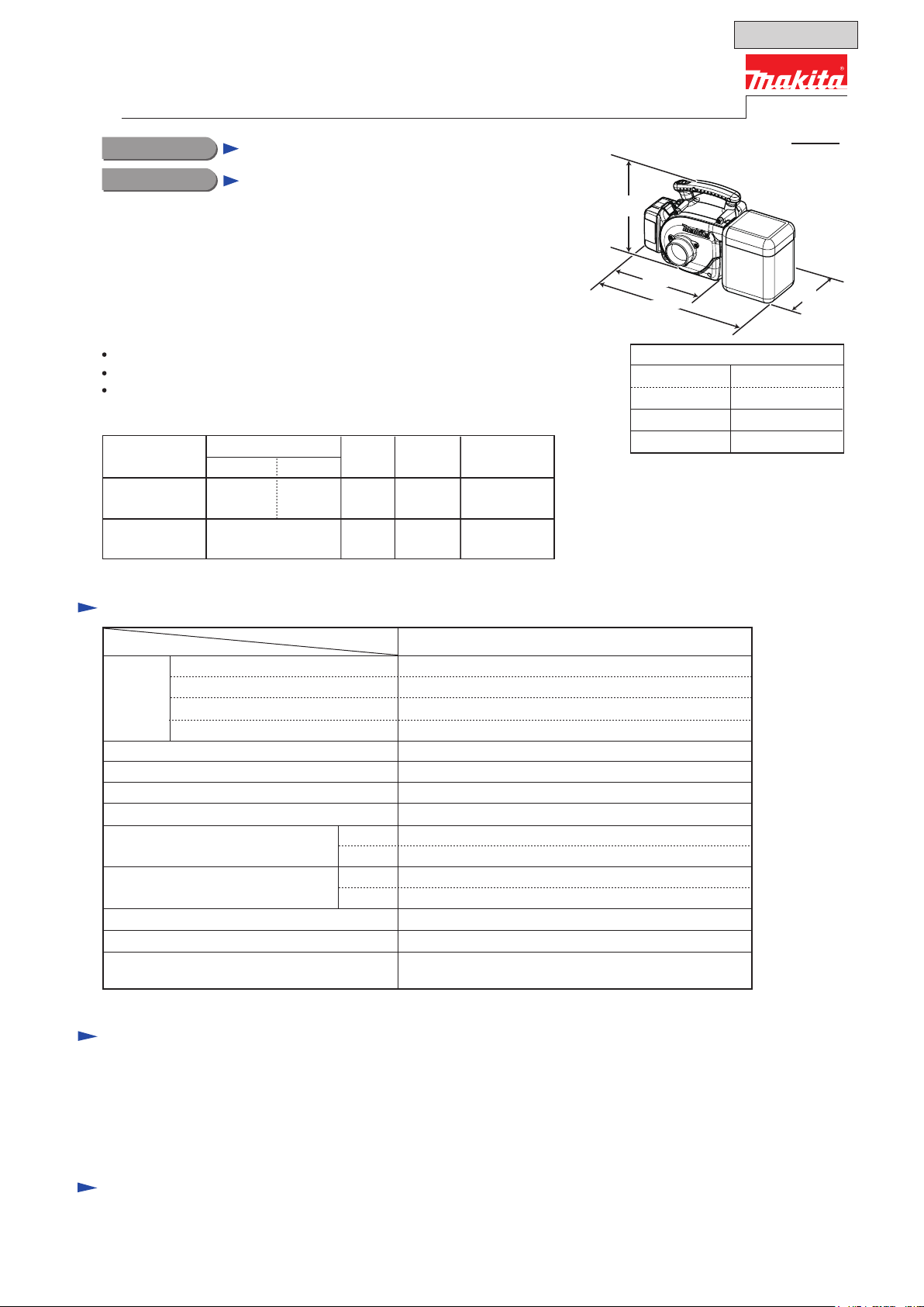
Dimensions*2: mm (")
Width (W)
Height (H)
Length (L1*3) 273 (10-3/4)
Length (L2*4) 403 (15-7/8)
195 (7-5/8)
226 (8-7/8)
Battery
Max. sealed suction: kPa (mmH2O)
Charging time (approx.): min.
Continuous run time (approx.)
on a single full battery charge: min.
Weight according to
EPTA-Procedure 01/2003*5: kg (lbs)
Dust bag capacity: L
Capacity: Ah
Cell
Voltage: V 18V
5.5 (560)
Air volume setting Yes (2 settings: High/ Low)
Max. air velocity: m/sec
3.0
Soft start Yes
13 (with Battery BL1830)
26 (with Battery BL1830)
2.2 (4.8)
1.3/ 3.0
Li-ion
3.4
15/ 22 with DC18RA
94
Max. air volume: m3/min.
*5 With Battery BL1815; without Nozzle assembly, Dust bag assembly, Hose complete
This product is available in the following variations:
BVC350RF
No
Model No. type quantity Charger
No
Battery
cover
Makita blue
DC18RA
BVC350Z NoNo
1BL1830 Makita blue
Housing
color
Battery
Nozzle assembly ........................................................... 1
Dust bag assembly (cloth) ............................................. 1
Hose complete ø28-2.5 (with Front cuff 22) ............... 1
Front cuff 38 .................................................................. 1
Shoulder belt ................................................................. 1
Battery BL1830
Battery BL1815
Fast charger DC18RA
Charger DC18SD
Charger DC24SC
Automotive charger DC18SE
Model BVC350 is a Cordless vacuum cleaner powered by 18V
Li-ion battery; compatible with both 3.0Ah battery BL1830 and
1.3Ah battery BL1815.
Its main benefits are:
Cordless design for high portability
Large 3L dust bag capacity
High/Low air volume settings to suit your application
High
Low
Suction power: W 50
15
High
Low
The models also include the accessories listed below in "Standard equipment".
Specification Model BVC350
TECHNICAL INFORMATION
*2 With Battery BL1830
*3 L1: without Dust bag assembly
*4 L2: with Dust bag assembly
L1
L2
H
W
OFFICIAL USE
for ASC & Sales Shop

P2/ 7
Repair
CAUTION: Repair the machine in accordance with “Instruction manual” or “Safety instructions”.
[1] NECESSARY REPAIRING TOOLS
[2] DISASSEMBLY/ASSEMBLY
[2]-1. Fan 86
Code No. Description Use for
782209-3 Socket wrench 9 Removing/ tightening M5x10 Hex flange head bolt
DISASSEMBLING
Remove Fan 86 as illustrated in Fig. 1.
Note: 1) Separate Front cover complete from Fan cover first, because there is a 4x75 Tapping screw to fasten Fan cover
under Front cover complete.
2) Blow away the remaining dust in Motor housing set when disassembling it.
4x18 Tapping
screws (3pcs.)
4x18 Tapping screw (2pcs.)
4x75 Tapping
screw (3pcs.)
Front cover complete
1. Remove Front cover complete and 4x18 Tapping screws.
Pin 4 comes into sight as illustrated below.
2. Remove Pin 4, two 4x18 Tapping screws and three
4x75 Tapping screws, and then separate Fan cover
from Motor housing set.
Fan 86 comes into sight.
Pin 4
Note: Do not turn over the machine without removing Pin 4
from Motor housing set.
Fig. 1
Pin 4
Cap 19 hooked with
the notch of Motor
housing set
Cap 19
Joint
Fan cover
Fan 86
Seal ring
Flat washer 10
5. Fan 86 can be removed with Flat washer 10
attached on the reverse.
Motor housing set
Fan cover
Socket wrench 9
Note: Flat washer 10 may fall off Motor shaft,
or may be left on.
Do not miss it.
3. Cap 19 illustrated below is easy to fall off
Motor housing set.
Therefore, remove it in advance.
4. While holding Fan 86 by gloved hand,
remove Max Hex flange head bolt by
turning Socket wrench 9 counterclockwise.

P3/ 7
Repair
[3] DISASSEMBLY/ASSEMBLY
[3]-1. Fan 86 (cont.)
[3]-2. DC Motor, Controller , Switch unit
ASSEMBLING
DISASSEMBLING
Half cylinder shape of
Front cover complete
Fig. 2
Fig. 3
(1) Separate Fan cover from Motor housing set then remove Fan 86 as illustrated in Fig. 1.
(2) Electrical parts can be replaced as illustrated in Fig. 3.
(3) Remove DC motor as illustrated in Fig. 4.
(4) Remove M5x10 Hex flange head bolt and Fan 86 again, and then pull off Motor rubber rings A and B from DC motor.
(Fig. 5)
2. Disconnect Connector.
Switch unit, Controller and Terminal can be
removed.
Switch plate
Motor housing set
Ring
Connector
Switch unit
Terminal
Controller
1. Remove Switch plate and Ring
after removing Fan cover.
Half cylinder shape
of Fan cover
Take the disassembling the step in reverse.
Note: Be sure to put Flat washer 10 in place.
Pass Pin 4 through Fan cover and Motor housing set before
assembling Front cover complete to Fan cover.
Half cylinder shape of Front cover complete must not rise
from that of Fan cover after Fan cover is secured with
three 4x18 Tapping screws. Therefore, tighten their screws
while pushing down the shapes. (Figs. 1 and 2)
Cap 19 mentioned in
after Fan cover is assembled to Front cover complete.
Fig. 1 must be inserted into Housing set
Assemble Fan 86 to Motor shaft provisionally
to remove DC motor from Motor housing set.
Fig. 4
Fig. 5
M5x10 Hex
Flange Head Bolt
Fan 86
Fan 86
Grounding lead wire
Motor rubber ring A
Motor rubber
ring B
Grounding lead wire
Motor rubber ring BDC motor
Cap
Motor rubber ring A with
Ball bearing 6000DDW
Disconnect Grounding lead wire from
Motor housing set, then pull off the Fan 86.
DC motor with Motor rubber rings A and B
can be removed.

P4/ 7
Repair
[3] DISASSEMBLY/ASSEMBLY
[3]-2. DC motor, Controller, Switch unit (cont.)
ASSEMBLING
Insert DC motor section to Motor housing set.
Red marking as a distinction
of positive terminal
If the wire connecting portion faces
the opposite side to Lead wire holder
of Motor rubber ring B, Lead wires
interfere with assembly of DC motor
to Motor housing set.
(1) After setting the new electrical parts to Motor housing set, put Switch plate and Ring to Motor housing set.
Refer to the top left illustration in Fig. 3.
(2) Assemble Motor rubber ring B to DC Motor as illustrated in Fig. 6R.
Wire connecting
portion
Lead wire (red)Lead wire (black)
Motor rubber
ring B
Fig. 6R
Fig. 7
Fig. 6F
Motor housing set
Fit Motor rubber ring B to
the Terminal side of
DC Motor.
Connect the Controller’s Lead wires
(black, red) to DC motor.
Be careful about the following matters.
* Face the wire connecting portion of
Flag connectors to Lead wire holder
side of Motor rubber ring B.
* Connect Lead wire (red) with
the positive terminal of DC motor.
Lead wire holder
of Motor rubber ring B
Fix the Lead wires with
Lead wire holder.
Motor rubber ring B
Do not cross Lead wires.
Note: Do not block up the vents of DC motor
with Motor rubber ring B.
(3) Put Cap on the protrusion of DC motor. (Fig. 5) Insert DC Motor into Motor housing set as illustrated in Fig. 7.

P5/ 7
Repair
[3] DISASSEMBLY/ASSEMBLY
[3]-2. DC motor, Controller, Switch unit (cont.)
ASSEMBLING
Fig. 8
Fig. 9
(6) Take the disassembling step in reverse to reassemble the removed parts.
Motor rubber ring A is set in place by assembling Motor housing set.
Aligning these protrusions to
the ribs of Motor housing set,
put Motor rubber ring A on
DC Motor in Motor housing set.
Rib
Motor rubber ring A with Ball bearing 6000DDW
As the stepped portion of Motor drum interferes in insertion of
Grounding terminal, bend the grounding terminal in advance.
Motor
drum
Insert Grounding terminal deep into the gap
between Motor rubber ring A and DC Motor.
Make sure that Grounding terminal
is set in place as illustrated below.
Motor rubber
ring A
Grounding terminal
Grounding Terminal
Motor rubber ring A
Motor rubber ring A
Grounding terminal
Grounding terminal
Motor
drum
Motor
drum
less than 3mm
Motor rubber ring A
Lead wire
(transparent)
Flat washer 10
Spindle top protruded from
Ball bearing 6000DDW
Note: Do not fit Motor rubber ring A to
Motor housing set completely
in this step.
(4) Insert Motor rubber ring A between Motor housing set and DC motor, then pass Flat washer 10 through Spindle.(Fig. 8)
Note: Push down Motor rubber ring A so that Spindle top can protrude from Ball bearing 6000DDW as illustrated in Fig. 8.
(5) Set Grounding terminal in place. Refer to Fig. 9.
Note: Regarding the opposite Grounding terminal of Lead wire (transparent), Refer to Fig. D-4.

Circuit diagram
Wiring diagram
P6/ 7
White Blue
Color index of lead wires' sheath
Black
Red
Fig. D-1
Transparent
Put Line filter between
DC motor and Controller.
Refer to Fig. D-2.
Yellow
Line filter (if used)
DC motor
Grounding Terminal to be
connected to Motor Housing set.
Refer to Fig. D-4.
Grounding Terminal
to be connected to
Drum of DC motor.
Refer to Fig. 9.
Terminal
Controller
Switch
unit
Grounding
Lead wire
Fig. D-2
Pass the Controller’s lead wires (black, red)
through Line filter.
Note: 1) Line filter is not used for some countries.
2) Be sure to see Figs. 6R and 6F.
DC motor and Line filter
Line filter
(if used)
Controller’s lead
wires (black, red)
Line filter
(if used)
Connect Flag connectors to Terminals of DC motor so that
the wire connecting portions faces the Lead wire holder side.
Lead wire holder of
Motor rubber ring B
Wire connecting portion
on Flag connector
Fig. D-3
Terminal
Wire connecting portion
Flag connector
Terminal
Marks of positive and negative terminals.
Face the wire connecting portions of Flag connectors
to the marks of positive and negative terminals.

Wiring diagram
P7/ 7
Motor housing
Grounding
lead wire
(transparent)
Fit Grounding terminal into the
groove of Motor housing set.
Be careful to the direction of
Grounding terminal.
Refer to Fig. D-1.
Hole for Pin 4
(Refer to Fig.1.)
Put the sag portion of
Grounding lead wire
in this area.
Line filter
(if used)
Controller
Connector
Put the sag portion of Controller’s
Lead wires in this area.
Terminal
Fix Grounding lead wire
with Lead wire holder here.
The Lead wires connected to
Connector have to be fixed
with these Lead wire holders.
Fix Lead wires (black, red)
for connecting DC motor
and Controller with
Lead wire holder here.
Place Line filter here.
Fig. D-4
This manual suits for next models
2
Table of contents
Other Makita Vacuum Cleaner manuals

Makita
Makita GCV06 User manual

Makita
Makita DCL182 User manual

Makita
Makita CL104DWY User manual

Makita
Makita VC4210M User manual

Makita
Makita DCL280FTC User manual

Makita
Makita DVC153L User manual

Makita
Makita VC2211M Manual

Makita
Makita DVC860L User manual

Makita
Makita DVC860L User manual

Makita
Makita DVC350F User manual

Makita
Makita 446 L User manual

Makita
Makita BCL140 User manual

Makita
Makita DVC350Z User manual

Makita
Makita DCL500 User manual

Makita
Makita DVC340 User manual

Makita
Makita VC007GL User manual

Makita
Makita DCL181F User manual

Makita
Makita DVC750L User manual

Makita
Makita DCL180 User manual

Makita
Makita DRC300 User manual