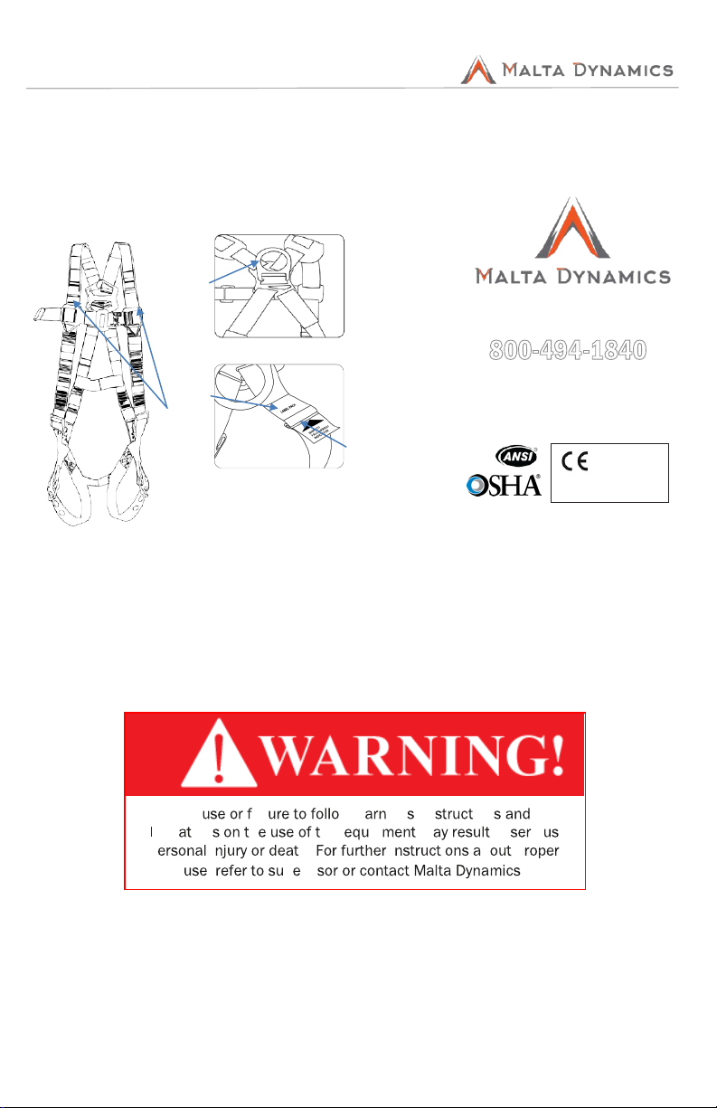
Full Body Harness Instruction Manual
Materials and Construction
Webbing Materials
•Constructed with high tenacity polyester; breaking strength >5000 lbs tensile strength
•Constructed with Aramid, breaking strength > 5000 lbs tensile strength
Pad and Label Cover Materials
•All outer fabric: Nomex and Kevlar blend fabric
•Fire Resistant hook and loop fasteners
•Nylon and Polyester blend
Connector Materials
•Galvanized Steel
Purpose
Malta Dynamics Full Body Harnesses are Class 3 full body harnesses designed for an array of full-
body applications. Such full body harnesses are the only form of body wear acceptable for fall arrest.
Full-body harnesses may also be used for positioning, travel restraint and rescue.Malta Dynamics
harnesses are designed and tested to comply with applicable OSHA and ANSI standards for fall
protection equipment. When used as a component in a personal fall arrest system, or a personal
restraint system, Malta Dynamics full body harnesses comply with OSHA directives for fall protection
wear. Full body harnesses help absorb the impact forces and keep the body upright should a fall
occur.
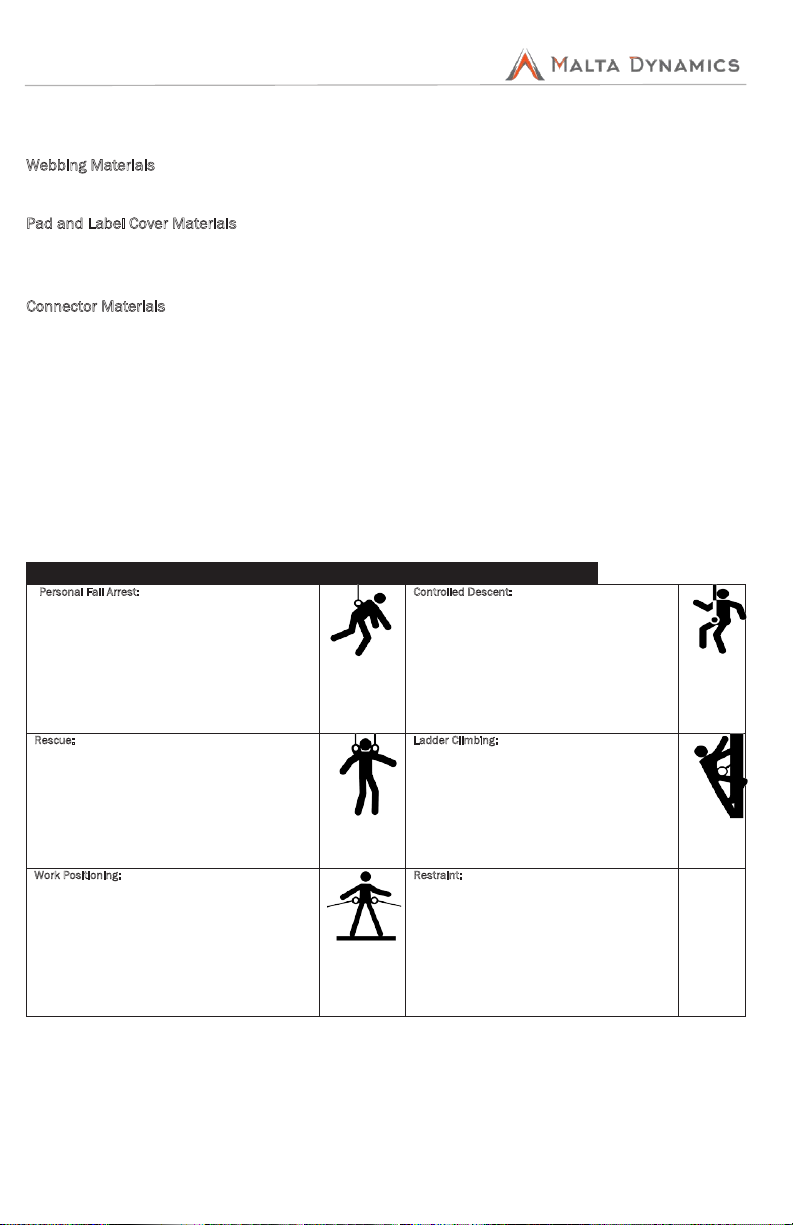
Illustration 1: Applications
The full body harness is used as a component of a
personal fall arrest system. Personal fall arrest
systems typically include a full body harness and a
connecting subsystem (energy absorbing lanyard).
Maximum arresting force must not exceed 900 lbs (4
kN), for fall arrest applications connect the fall arrest
subsystem (example: lanyard, SRL, energy absorber,
etc.) to the D-ring or attachment element on your
back, between your shoulder blades.
For controlled descent applications, full body
harnesses equipped with a single sternal level D-
ring, one or two frontal mounted D-rings, or a pair
of connectors originating below the waist (such as
a seat sling) may be used for connection to a
descender or evacuation system.
The full body harness is used as a component of a
rescue system. Rescue systems are configured
depending on the type of rescue. For limited access
(confined space) applications, harnesses equipped
with D-rings on the shoulders may be used for entry
and egress into confined spaces where worker profile
is an issue.
The full body harness is used as a component of a
climbing system to prevent the user from falling
when climbing a ladder or other climbing structure.
Climbing systems typically include a full body
harness, vertical cable or rail attached to the
structure, and climbing sleeve. For ladder climbing
applications, harnesses equipped with a frontal D-
ring in the sternal location may be used for fall
arrest on fixed ladder climbing systems.
The full body harness is used as a component of a
work positioning system to support the user at a work
position. Work positioning systems typically include a
full body harness, positioning lanyard, and a back-up
personal fall arrest system. For work positioning
applications, connect the work positioning subsystem
(example: lanyard, Y-lanyard, etc.) to the lower (hip
level) side or belt mounted work positioning
attachment anchorage elements (D-rings). Never use
these connection points for fall arrest.
The full body harness is used as a component of a
restraint system to prevent the user from reaching
a fall hazard. Restraint systems typically include a
full body harness and a lanyard or restraint line.
2 19
Full Body Harness Instruction Manual
chest strap to slide up and possibly choke the user during a fall, extraction, suspension, etc.
The competent person should consider Full Body Harness models with a fixed sternal
attachment for these applications.
12. Frontal –The frontal attachment serves as a ladder climbing connection for guided type fall
arresters where there is no chance to fall in a direction other than feet first, or may be used for
work positioning. Supporting the user, post fall or during work positioning, by the frontal
attachment will result in a sitting body position, with the upper torso upright, with weight
concentrated on the thighs and buttocks. When supported by the frontal attachment the
design of the Full Body Harness shall direct load directly around the thighs and under the
buttocks by means of the sub-pelvic strap. If the frontal attachment is used for fall arrest, the
competent person evaluating the application should take measures to ensure that a fall can
only occur feet first. This may include limiting the allowable free fall distance.
13. Shoulder –The shoulder attachment elements shall be used as a pair, and are an
acceptable attachment for rescue and entry/retrieval. The shoulder attachment elements
shall not be used for fall arrest. It is recommended that the shoulder attachment elements
be used in conjunction with a yoke which incorporates a spreader element to keep the Full
Body Harness shoulder straps separate.
14. Waist, Rear –The waist, rear attachment shall be used solely for travel restraint. The
waist, rear attachment element shall not be used for fall arrest. Under no circumstances is
it acceptable to use the waist, rear attachment for purposes other than travel restraint. The
waist, rear attachment shall only be subjected to minimal loading through the waist of the
user, and shall never be used to support the full weight of the user.
15. Hip –The hip attachment elements shall be used as a pair, and shall be used solely for
work positioning. The hip attachment elements shall not be used for fall arrest. Hip
attachments are often used for work positioning by arborists, utility workers climbing poles
and construction workers tying rebar and climbing on form walls. Users are cautioned
against using the hip attachment elements (or any other rigid point on the Full Body
Harness) to store the unused end of a fall arrest lanyard, as this may cause a tripping
hazard, or, in the case multiple leg lanyards, could cause adverse loading to the Full Body
Harness and the wearer through the unused portion of the lanyard.
16. Suspension seat –The suspension seat attachment elements shall be used as a pair,
and shall be used solely for work positioning. The suspension seat attachment elements
shall not be used for fall arrest. Suspension seat attachments are often used for prolonged
work activities where the user is suspended, allowing the user to sit on the suspension
seat formed between the two attachment elements. An example of this use would be
window washers on large buildings.
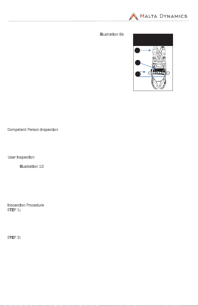
User Inspection, Maintenance and Storage of Equipment
Users of personal fall arrest systems shall, at a minimum, comply with all manufacturer
instructions regarding the inspection, maintenance and storage of the equipment. The user’s
organization shall retain the manufacturer’s instructions and make them readily available to all
users. See ANSI/ASSE Z359.2, Minimum Requirements for a Comprehensive Managed Fall
Protection Program, regarding user inspection, maintenance and storage of equipment.
1. In addition to the inspection requirements set forth in the manufacturer’s instructions, the