Mandam ORKAN 3+ User manual


2
DECLARATION OF CONFORMITY
FOR A MACHINE
In accordance with the Ordinance of the Minister of the Economy dated 21 October 2008 (Journal of Laws No. 199, item
1228)
and the Directive of the European Union no. 2006/42/EC of 17 May 2006
MANDAM Sp. z o.o.
ul. Toruńska 14
44-100 Gliwice
hereby declares at its sole responsibility that the following machine:
under this declaration, complies with:
the Ordinance of the Ministry of Economy of 21 October 2008 on fundamental
requirements for machinery (Journal of Laws No. 199, item 1228)
and the Directive of the European Union 2006/42/EC of 17 May 2006.
Persons responsible for the technical documentation for the machine: Jarosław Kudlek, Łukasz
Jakus
ul. Toruńska 14, 44-100 Gliwice, Poland
For assessment of compliance the following standards have been applied:
PN-EN ISO13857:2010
PN-EN ISO4254-1:2016-02
PN-EN ISO12100-1:2005/A1:2012
PN-EN ISO12100-2:2005/A1:2012
PN-EN 982+A1:2008
This EC Declaration of Conformity shall be cancelled
if the machine is modified orredesigned without consent of the manufacturer.
……………………………………… ………………………………………
Place and date of issue First and last name, position held
and signature of the person authorized
ORKAN / ORKAN VARIO / ORKAN RESOR PLOUGH
type/model: ……………………………..
year of manufacture: ……………………
serial number: ………………….

3
1Introduction ..................................................................................................................................4
1.1. Safety symbols and inscriptions............................................................................................5
2General information......................................................................................................................8
2.1. Design of the ORKAN / ORKAN VARIO / ORKAN RESOR PLOUGH. ..........................8
2.2. Intended use of the ORKAN / ORKAN VARIO / ORKAN RESOR plough .....................10
3General safety information .........................................................................................................12
3.1. Hitching and unhitching from the tractor............................................................................13
3.2. Tyres ....................................................................................................................................13
3.3. Hydraulic system.................................................................................................................13
3.4. Transport safety on public roads .........................................................................................14
3.5. Residual risk description .....................................................................................................15
3.6. Residual risk assessment .....................................................................................................16
4Plough and tractor settings .........................................................................................................16
4.1. Preparing the plough ...........................................................................................................18
4.2. Selection of the hitching bar................................................................................................18
4.3. Hitching the plough to the tractor........................................................................................18
4.4. Adjustment of the hitching bar height.................................................................................19
4.5. Adjustment of the ploughing width.....................................................................................20
4.5.1 ORKAN and ORKAN RESOR plough ................................................................................20
4.5.2 ORKAN VARIO plough .......................................................................................................21
4.6. First furrow-slice adjustment...............................................................................................22
4.7. Levelling..............................................................................................................................22
4.8. Working depth adjustment...................................................................................................23
4.9. Coulter disc blade................................................................................................................24
4.10. Plough share ....................................................................................................................25
4.11. ORKAN and ORKAN VARIO skimmer.........................................................................25
4.12. ORKAN RESOR skimmer ..............................................................................................26
4.13. Assembly and disassembly of the last pair of bodies ......................................................27
4.14. Spring protection .............................................................................................................27
5Operation of ORKAN / ORKAN VARIO / ORKAN RESOR plough.......................................28
5.1. Lubrication ..........................................................................................................................28
5.2. Worn out components..........................................................................................................29
5.3. Screw tightening torque.......................................................................................................30
5.4. Securing bolts......................................................................................................................31
5.5. Gauge wheel........................................................................................................................31
5.6. Hydraulic system.................................................................................................................31
6Storage of ORKAN / ORKAN VARIO / ORKAN RESOR plough...........................................32
7Disassembly and withdrawal from service and scrapping..........................................................32

4
8Technical characteristics.............................................................................................................33
9ORKAN, ORKAN VARIO, ORKAN RESOR ploughspare parts .............................................34

5
1 Introduction
Congratulations on your purchase of the ORKAN VARIO plough. This instruction
manual provides information on the hazards that may occur during use, plough operation,
technical data and the most important indications and recommendations the knowledge
and use of which is a prerequisite for proper operation. Keep this manual for future
reference. Should you have any problems with understanding any statement in the
instruction manual, please contact the manufacturer.
The following mark indicates the guidelines that are important due to safety reasons:
Machine identification
Identification data of the plough, including basic information on the manufacturer and the
machine and CE marking, can be found on the rating plates placed on the load-bearing
frame.
The warranty for the plough is valid for 12 months from the date of sale.
The warranty card constitutes an integral part of the machine.
Whenever you request any information on spare parts, provide the serial number.
For more information on spare parts:
•please visit our website at: http://mandam.com.pl/parts/
•call us at +48 668 662 289
•e-mail us at: [email protected]

6
1.1. Safety symbols and inscriptions
CAUTION! Special care must be taken when using the implement in case of
areas marked with special information and warning signs (yellow stickers).
The following symbols and inscriptions can be found on the implement. Secure the
symbols, signs and inscriptions against loss and make sure they are legible at all times. If
lost and illegible, replace the symbols, signs and inscriptions with new ones.
Table 1. Information and warning signs
Safety sign
Meaning of the safety sign
Location on the implement
Read the instruction
manual prior to operating
the implement
Frame adjacent to the mounting
place of the upper fastener
Danger of toe or foot crush Frame adjacent to the mounting
place of the upper fastener
Keep clear from lift bars
while controlling the lift
Frame adjacent to the mounting
place of the upper fastener
Keep clear from foldable
and moving parts of the
implement
Rear part of the frame

7
Safety sign
Meaning of the safety sign
Location on the implement
Liquid jet under pressure –
hazard of bodily injury Cylinders
Fixing point for transport
belts
Upper part of the drawbar (upper
fastener pin)
Rear part of the plough frame

8
2 General information
2.1. Design of the ORKAN / ORKAN VARIO / ORKAN RESOR PLOUGH.
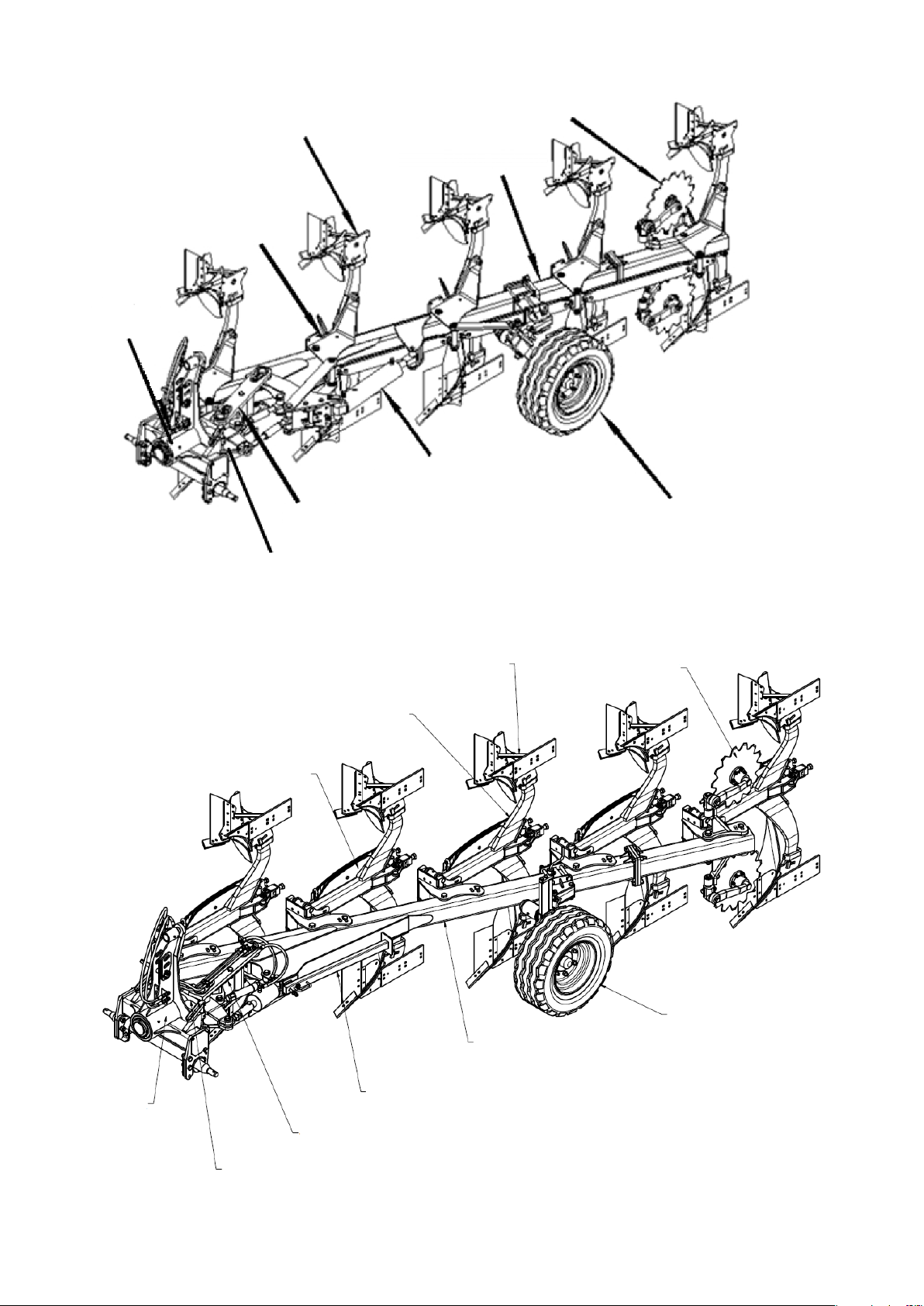
Fig. 1. Design of the ORKAN plough and the work tool.
Body
Body holder
Head
Coulter disc blade
Front member Fastener
Support foot Main frame
Gauge wheel
Standard
Mouldboard shin
Breakaway bolt
Mouldboard wing
Plough share Share point
9
Fig. 2. Design of the ORKAN VARIO plough.
Fig. 3. Design of the ORKAN RESOR plough and the work tool.
Actuator responsible for
smooth adjustment of
working width Gauge wheel
Head
Fastener
Front member
Body holder
Body
Main frame
Coulter disc blade
Front
member
Head
Fastener
Support foot
Main frame
Gauge wheel
Coulter disc
blade
Body
Body holder
Spring

10
Fig. 4. Design ofthe ORKAN RESOR work tool.
2.2. Intended use of the ORKAN / ORKAN VARIO / ORKAN RESOR plough
The plough is intended for tillage on poorly stoned soils. Its purpose is to cut off
field’s earth from undisturbed soil, shift and turn it over in order to cover over crop residue
and to loosen the soil.
The working components are right- and left-hand plough bodies equipped with 18”
plough shares, reversible share points, and full semihelical or openwork cylindrical
mouldboards.
Full semihelical mouldboard
Recommended for medium and light soils. Ideal for
co
vering over crop residues and characterized by a low
soil loosening intensity. It creates a wide furrow,
allowing for cooperation with tractors with tractors
with wide tyres.
Openwork cylindrical mouldboard
Recommended for heavy (compacted) soils.
Ideally
loosens the soil and thanks to the mouldboard being of
an openwork structure, ploughing resistance is
reduced.
Plough share (trash board)
Spring
Standard
Share point
Plough share
Mouldboard wing

11
Provides good coverage of crop residues and organic
fertilizers. Allows for a large space to be maintaine
d
between the plough bodies.
Skimmer
Recommended for efficient deep ploughing on soils
with a large amount of crop residues and stubble
(especially corn for medium to shallow ploughing) and
organic fertilizers.
Coulter disc blade
The
coulter disc blade installed on the last pair of
bodies ensures a proper shape of the furrow. It creates
a lower working draft and operating resistance while
compared to a knife coulter.
Gauge wheel
It ensures the maintenance of the working depth and
copying, providing a uniform working depth
irrespective of the unevenness of the surface.

12
Mouldboard extension
It ensures correct arrangement of the furrow
especially during the ploughing of stubble and areas
covered by sod.
Coulter knife blade
Alternative to the coulter discs when reduction of mass
is necessary. It is also recommended for large
quantities of crop residues, organic fertilizers or
stony soils when a coulter disc blade would be
blocked.
CAUTION! This plough is exclusively intended for agricultural work – soil
cultivation. Using the implement for tasks that differ from the intended use
shall be regarded as misuse, resulting in loss of warranty.
CAUTION! The manufacturer shall not be liable for any damage arising out of
misuse. Failure to follow the guidelines included in this instruction manual
shall also be regarded as misuse.
3 General safety information
The plough can only be started, used and repaired by persons familiar with its
operation and that of the tractor being used and the rules for its safe use and operation.
The manufacturer shall not be liable for any unauthorised alternation of the plough. Only
genuine original MANDAM spare parts shall be used during the warranty period.
The plough must be operated with all precautionary measures, in particular:
•each time before starting operation check the plough and the tractor whether their
condition guarantees safety during operation and travel,
•minors, disabled or intoxicated persons (under the influence of alcohol or drugs)
must not operate the implement,
•wear work clothes, shoes and gloves during maintenance,
•do not exceed the maximum axle loads, tyre pressure and transport dimensions,
•use only original cotter pins and pins,
•do not approach the plough when it is being lifted or lowered,
•do not stay between the plough and the tractor when the engine is running,

13
•move forward, lift and lower the roller slowly and smoothly without sudden jerks,
making sure that nobody stays in the vicinity,
•do not reverse and make U-turns when the implement is lowered to the working
position,
•when making U-turns do not use independent tractor brakes,
•do not stand on the implement or apply additional loads during operation and
transport,
•while making U-turns, pay due caution if anyone is in the vicinity,
•do not operate the plough on slopes with the inclination exceeding 12°,
•any repairs, lubrication or cleaning of working components may be performed as
long as the engine is not running and the plough is lowered,
•there is a hazard of head injury when you perform maintenance or replacement of
parts under the implement without adequate protection – wear a hardhat,
•during a break in the work, always lower the implement to the ground and stop the
tractor engine,
•the plough is equipped with a mechanical lock to prevent uncontrolled rotation
during transport,
•driving and parking the implement on an unstable slope may cause soil slipping and
machine sliding,
•store the implement in a manner preventing injury to people and animals.
3.1. Hitching and unhitching from the tractor
•Make sure that the plough is hitched to the tractor in accordance with the
instructions, remembering to secure the bolts and that the bolts are secured with
cotter pins.
•While hitching the tractor with the plough, do not stay between the implement and
the tractor.
•The tractor used together with the plough must be fully functional and in good
working order. Do not attach the implement to a tractor with a malfunctioning or
defective hydraulic system.
•Remember to observe the following: balance of the tractor and the plough, tractor
steerability and braking performance – the front axle load must not drop below 20%
of the total tractor load – a kit of front weights.
•When in resting position and disconnected from the tractor, the machine must be
stable all the time.
•Place the supporting foot on a stable ground. Do not use pads under the foot as this
may cause instability.
3.2. Tyres
•The tyre pressure must not exceed the tyre manufacturer’s recommended tyre
pressure rating (as indicated on the tyre wall).
•Badly damaged tyres (especially damage to the tyre profile) must be replaced
immediately.
•The repair works on wheels or tyres must be performed by persons trained and
authorised for this purpose. Such works must be performed with properly selected
tools.
3.3. Hydraulic system
The hydraulic system operates under high pressure. Take all precautionary measures, in
particular:

14
•do not connect and disconnect hydraulic hoses when the tractor hydraulic system
is pressurised (hydraulics set to neutral position),
•check regularly the conditions of connections and hydraulic hoses,
•do not use the implement until the hydraulic system is repaired.
3.4. Transport safety on public roads
For transport, the plough must be turned to the centre position (the frame should be in
the tractor’s axis) and then locked with a pin. Before turning, raise the plough to a point
where it does not interfere with the ground. During transport, the clearance under the
lowest part of the plough should prevent collision with the ground during transport on
uneven ground. When driving with the plough on public roads, it is mandatory to use
driving lights, a distinctive warning sign and side reflectors.
Do not exceed the speed limits during transportation, which are:
•up to 20 km/h on smooth-surface (asphalt) roads,
•6-10 km/h on country roads or cobblestones,
•up to 5 km/h on bumpy roads.
Adapt the driving speed to the road conditions to prevent the plough jumping on the three-
point hitch and to prevent excessive loads on the implement frame and the three-point
hitch.
Maintain particular caution when passing and overtaking and on bends. The permissible
width of the implement travelling on public roads is 3.0 m.
Do not drive with the implement if the slope is inclined crosswise to the implement by
more than 7°.
Be aware of the length of the plough. In sharp turns, the plough leans against the direction
of the turn. This may result in a collision with obstacles or other road users.
During transport the plough is to be secured with the lock that keeps the plough on the
same axis as the tractor, reducing its transport width and increasing the stability of the
vehicle during transport. For locking, use the lever that you need to turn so that it jumps
out of its slot and so that the pin holds the tow bar head in the locked position. Once
locked, the plough cannot be turned because damage to it may occur. To unlock, turn the
lock lever so that it falls back into its slot.

15
Fig. 5 Diagram of the plough lock lever.
While not working, the plough should be protected from tipping over by its support foot.
To this end, pull the protective pin towards you, then hold the foot’s handle and pull it
towards you. Turn the foot to its supporting position (by 90º) and release the handle.
Fig. 6 Plough support foot.
Warning! Failure to observe the above rules may pose hazard to the operator
and other people and can lead to the implement damage. The user shall be
liable for any damage caused by failure to observe the rules.
3.5. Residual risk description
Mandam Sp. z o.o. makes every effort to eliminate the risk of accidents. However,
Lock lever
Support foot
Locking bolt
16
there is some residual risk that may cause an accident. The biggest hazard occurs
when/during:
•using the implement for purposes other than described in the manual,
•operating the implement by people who are underage and do not have licences,
are ill or intoxicated,
•presence of people and animals within the implement operating range,
•precautionary measures are not taken during transport and maneouvering with the
tractor,
•anyone gets between the implement and the tractor while the tractor’s engine is
running,
•maintenance and when the service recommendations are not observed,
•driving on public roads.
3.6. Residual risk assessment
The residual risk can be minimised by applying the following recommendations:
•operate the implement carefully and without undue haste,
•read the instruction manual carefully,
•keep a safe distance from hazard zones,
•do not stay on the implement and within the implement operating range when the
engine is running,
•perform the maintenance in accordance with safety rules,
•wear safety clothes and a safety helmet while working under the implement,
•prevent the access of unauthorized personnel and especially children to the
implement.
4 Plough and tractor settings
The tractor selected for use with the plough should have the characteristics described in
the following paragraphs. The hydraulic system must be operational and efficient and have
two pairs of hydraulic couplings in accordance with ISO 7241-1 A, controlled by a twin
distributor. Pressure in both rear tyres should be the same in order to avoid formation of
uneven furrow-slices.
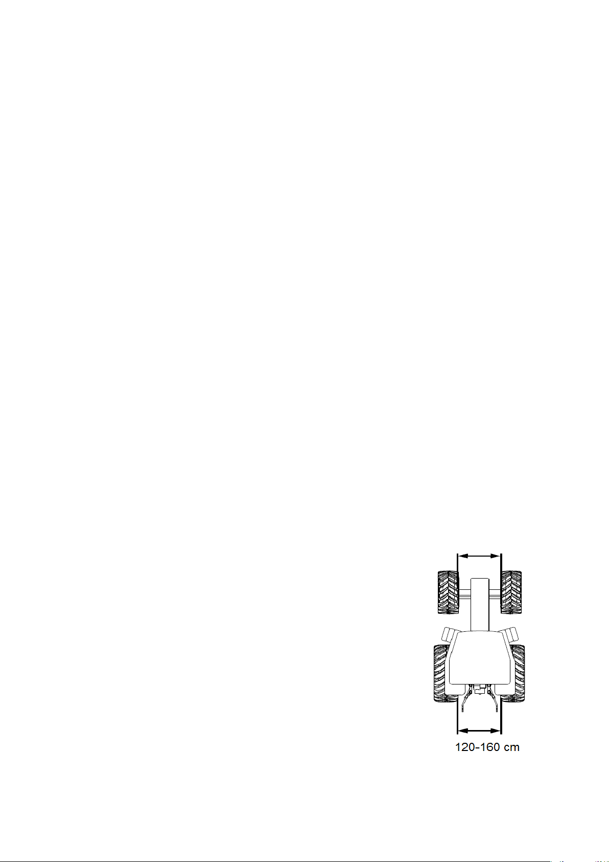
Tractor wheelbase – track
•The recommended tractor internal wheelbase – track
width (without the use of a furrow widener) should be
120 – 160 cm.
•The front track should be 0 – 10 cm wider than that of
the rear wheels.
0-10 wider than the rear

17
CAUTION! The permissible loads on the axles and tyre load capacities must
not be exceeded. The front axle load may not be less than 20%.
Axle load calculations
Key:
GC – the tractor weight,
TP – front axle load for the unhitched tractor,
TT – rear axle load for the unhitched tractor,
GT – total weight of the rear-mounted implement,
GP – total weight of the front-mounted implement,
a – distance between the centre of gravity of the front-mounted implement and the axle
centre,
b – tractor wheelbase,
c – distance between the rear axle centre and the centre point of the hitching pin of the
rear-mounted implement,
d – distance of the centre of gravity of the agricultural implement from the hitching pins
of the tractor,
x – distance of the centre of gravity from the rear axle (assume 0.45 if the manufacturer
does not provide this parameter).
Minimum load at the front in case of a rear-mounted implement:
Actual load on the front axle:
Actual total weight:
Actual load on the rear axle:
18
4.1. Preparing the plough
The plough is usually delivered for sale in a ready-to-operate condition. Due to the
limitations of the means of transport, it is also possible to deliver it in a partially
disassembled condition. Prior to operation check the technical condition of the plough, in
particular that of the working parts and screw connections.
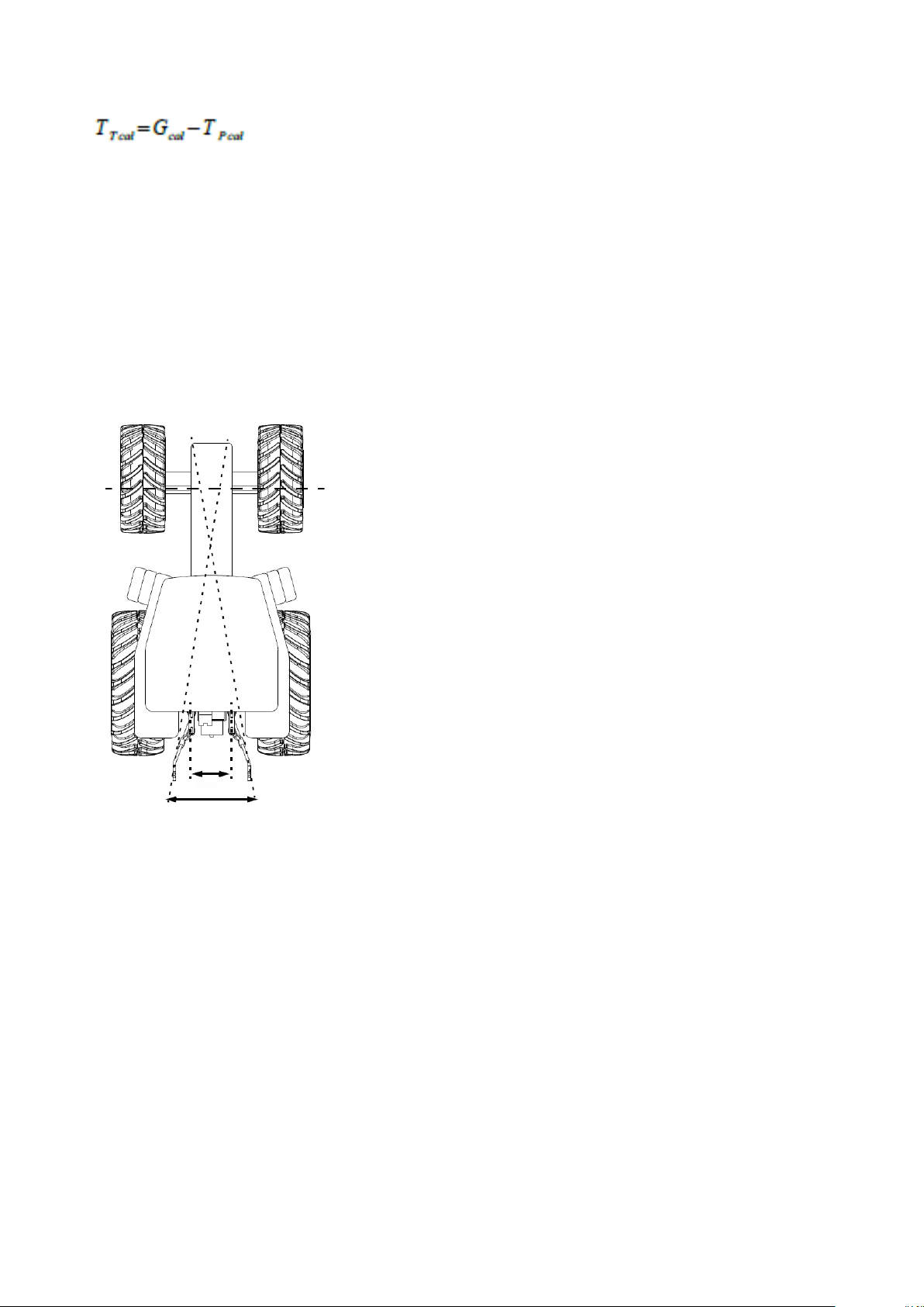
4.2. Selection of the hitching bar
In order to obtain a stable width of the first furrow-slice,
the theoretical intersection line of the lower bars of the
tractor’s hitch should be located in a distance equal to 1/3
of the tractor’s axle base, behind the front axle. Failure to
do this may cause the plough to “slew”. In such a case, a
hitching bar of a different length must be used.
4.3. Hitching the plough to the tractor
The lower bars of the three-point hitch should be at the same height, spaced
correspondingly to the spacing of the lower hitches of the plough. When hitching the
plough to the tractor, the implements should be placed on a hard and level surface. When
hitching the two pieces of machinery together, complete the following steps:
•suspend the hitching bar on the lower bars of the three-point hitch and secure with
cotter pins,
•switch the tractor hydraulic system into adjustment position,
•reverse carefully, suspend the implement on the bar and secure with pins,
•connect the tractor upper fastener (during operation of the implement, the hitch
point of the upper fastener on the implement must be located higher than the
attachment point of this fastener on the tractor),
•check the operation of plough lifting, lowering and the hydraulic system.
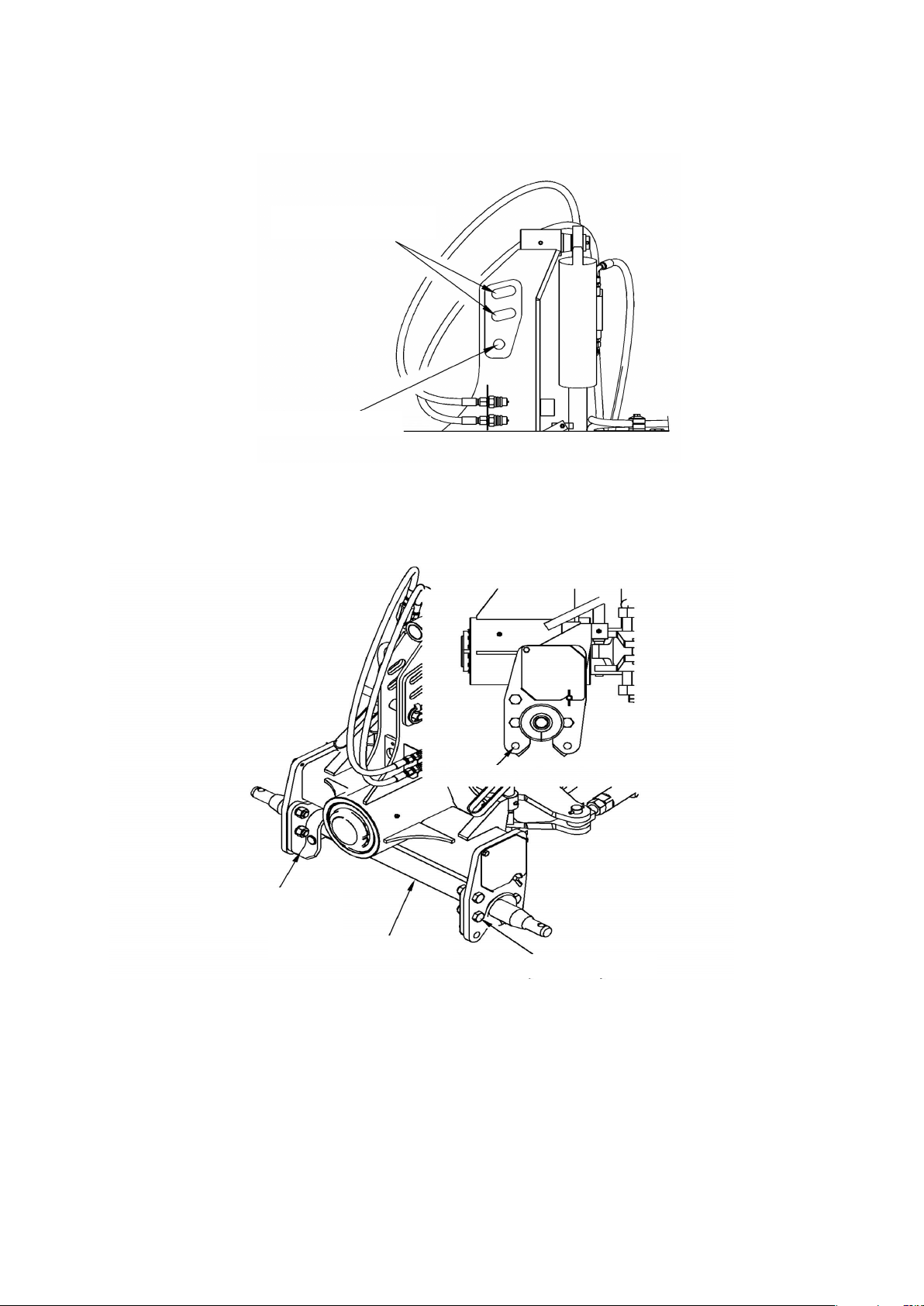
Connection of the upper fastener
•Oval (longitudinal) holes allow for better longitudinal ploughing of the terrain. Use
incorrect
correct
19
for 4-5 furrow plough, in extreme cases 3-furrow plough.
•A fixed hole prevents the plough from rising up on heavy and stony soils. Use for 2-
3 furrow ploughs.
Fig. 7 Using a suitable connection to the plough upper fastener.
4.4. Adjustment of the hitching bar height
Fig. 8 Schematic drawing of the hitching bar height adjustment.
The hitching bar can be set at the height of 64.5 cm and 57 cm from the ground depending
on the type of tractor operating the plough. In order to change the position of the hitching
bar, first remove the hitching bar from the plough hitch. Then turn the hitching bar handle
to the appropriate holes.
Larger ploughs
Smaller ploughs
Handle holes
Handle screws
Hitching bar
Hitching bar handle

20
4.5. Adjustment of the ploughing width
4.5.1 ORKAN and ORKAN RESOR plough
To change the working width of the ORKAN plough, first, change the angle of the bodies
to the frame bar. To this end:
•unscrew the M20 and remove the bolt from the hole,
•adjust the body so that the corresponding holes overlap,
•insert the bolt into the hole and tighten the nuts with a torque of 468 Nm.
Five working widths are available: 30 cm, 35 cm, 40 cm, 45 cm, 50 cm.
Fig. 9 Holes regulating the width of the implement.
Then, adjust the angle of the frame bar to the suspension so as to the body landsides are
parallel to the direction of travel. This is done with the external fastener screw between
the head and the frame beam. To this end:
•loosen the lock nut with a 46 wrench,
•then use a 46 wrench to set the appropriate angle of the frame,
•counter with a nut.
This manual suits for next models
11
Table of contents
Other Mandam Farm Equipment manuals

Mandam
Mandam MWC Series User manual

Mandam
Mandam MGX 2200 User manual

Mandam
Mandam KNIFE ROLLER 3.0 User manual

Mandam
Mandam GAL-C User manual

Mandam
Mandam MBS User manual

Mandam
Mandam BTH-D User manual

Mandam
Mandam ORKAN VARIO Series User manual

Mandam
Mandam SAL DISC HARROW User manual

Mandam
Mandam SUPER User manual

Mandam
Mandam Hybro 3,0 User manual


