Mandam SAL DISC HARROW User manual


2
EC DECLARATION OF CONFORMITY
FOR THE MACHINE
Pursuant to the Ordinance of the Minister of Economy of 21 October 2008 (Journal of Laws No. 199, item 1228)
and the Directive of the European Union 2006/42/EC of 17 May 2006
MANDAM Sp. z o.o.
ul. Toruńska 14
44 -100 Gliwice
declares with full responsibility that the machine:
under this declaration, complies with:
Ordinance of the Ministry of Economy of October 21, 2008 on the essential
requirements for machines (Journal of Laws No. 199, item 1228)
and the Directive of the European Union 2006/42/EC of 17 May 2006
Persons responsible for the technical documentation of the machine: Jarosław Kudlek,
Łukasz Jakus
ul. Toruńska 14, 44-100 Gliwice
The following standards were also used to assess compliance:
PN-ENISO13857:2010,
PN-ENISO4254-1:2016-02,
PN-ENISO12100-1:2005/A1:2012
PN-ENISO12100-2:2005/A1:2012
PN-EN982+A1:2008
This EC Declaration of Conformity loses its validity, if the machine is modified or converted
without the manufacturer's consent.
Gliwice 27.06.2019
Place and date of issue
Surname, first name, position and
signature of the authorized person
SAL DISC HARROW
type/model ………………………… .........................................
year of production: ...............................
Serial No.: ………………….

3
1. Introduction 4
1.1 Safety signs 6
2. Construction of SAL disc harrow 8
2.1 Purpose of the SAL disc harrow 9
3. General safety rules 9
3.1 Proper coupling and uncoupling with the tractor 10
3.2 Tyres 11
3.3 Hydraulic and pneumatic systems 11
3.4 Safety regarding transport on public roads 11
3.5 Description of residual risk 12
3.6 Assessment of residual risk 12
4. Information on handling and use 12
4.1 Preparing the disc harrow 13
4.2 Coupling the disc harrow to the tractor 15
4.3 Coupling the seed drill to the disc harrow 16
4.4 Operation and adjustment 17
4.4.1 Adjusting the shaft position 17
4.4.2 Setting up side screens 18
4.4.3 Setting up the work units 18
4.5 Rules for transporting the harrow on public roads and lighting the machine 21
4.6 Maintenance and lubrication 22
4.7 Torques for tightening screws 22
5. Operation 24
6. Replacement procedures 25
7. Storage of the disc harrow 26
8. Disassembly and disposal 27
9. Spare parts for the SAL disc harrow 27

4
1. Introduction
Congratulations on your purchase of the SAL disc harrow.
These instructions provide information on the hazards that may occur during use, harrow
operation, technical data and the most important indications and recommendations, the
knowledge and application of which are prerequisites for correct operation. Keep this
manual for future use. If you do not understand any of the provisions of this manual,
please contact the manufacturer.
Notes that are important for safety reasons are marked with the sign:
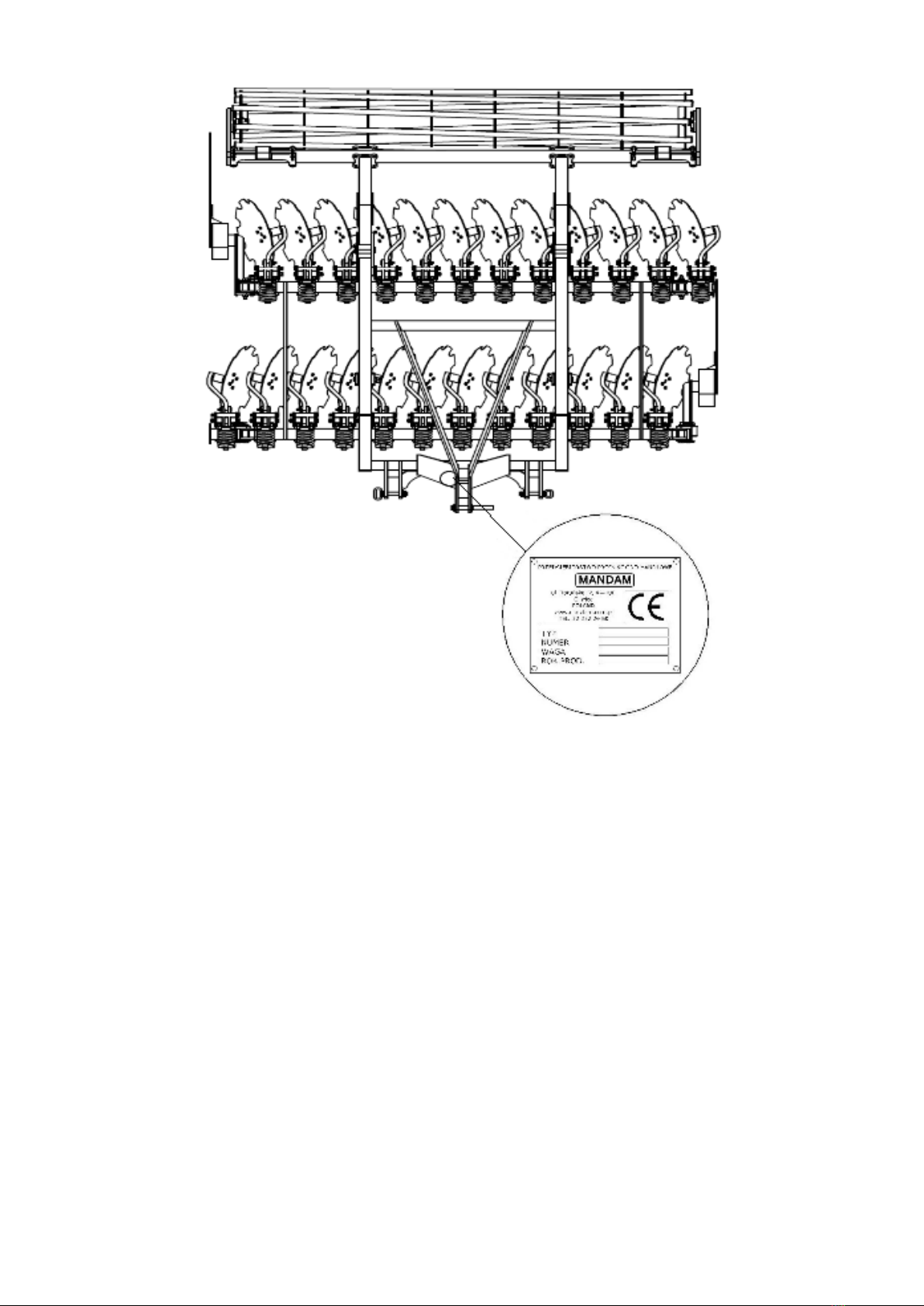
Machine identification
Identification data for the SAL harrow can be found on nameplates located on the
support frame (Fig.1), which includes the CE mark, basic information about the
manufacturer and the machine:
The guarantee on the harrow is valid for 12 months from the date of sale.
The warranty card is an integral part of the machine.
Please always quote the serial number when making enquiries about spare parts.
Information on spare parts can be found:
•on the web site: http://mandam.com.pl/parts/
•phone +48 668 662 289
•E-mail: [email protected]
5
Fig. 1 View of the SAL harrow with the location of the nameplate.
6
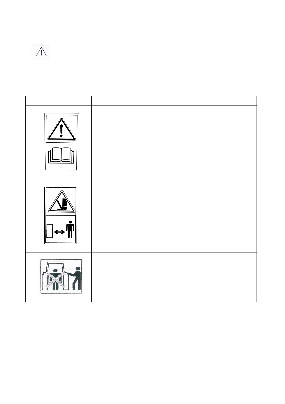
1.1 Safety signs
Remember! When using the disc harrow, special care should be taken in
areas marked with special information and warning signs (yellow stickers).
The signs and inscriptions on the machine are detailed below. Safety
signs and inscriptions should be protected against loss and loss of legibility. Signs and
inscriptions that are lost and illegible should be replaced with new ones.
Table 1 Information and warning signs
Safety signs
Meaning of the safety sign
Miejsce umieszczenia na maszynie
Read the operating
instructions before use.
Frame near mounting of the
upper fastener.
Crushing of the toes or
foot.
Frame near mounting of the
upper fastener.
Keep clear of the lift bars
while controlling the lift.
Frame near mounting of the
upper fastener.

7
Safety signs
Meaning of the safety sign
Miejsce umieszczenia na maszynie
Do not reach into the
crushing area if parts may
move
Mid frame near side frames
Pressurised liquid jet -
bodily harm
Cylinders
Fixing point for transport
belts
Upper part of the drawbar (upper
fastener bolt)
Rear frame part:
•rigid frame (adjacent to
the roller depth
adjustment)
•foldable frame (adjacent to
the upper fastener bolt on
the mid frame)
8
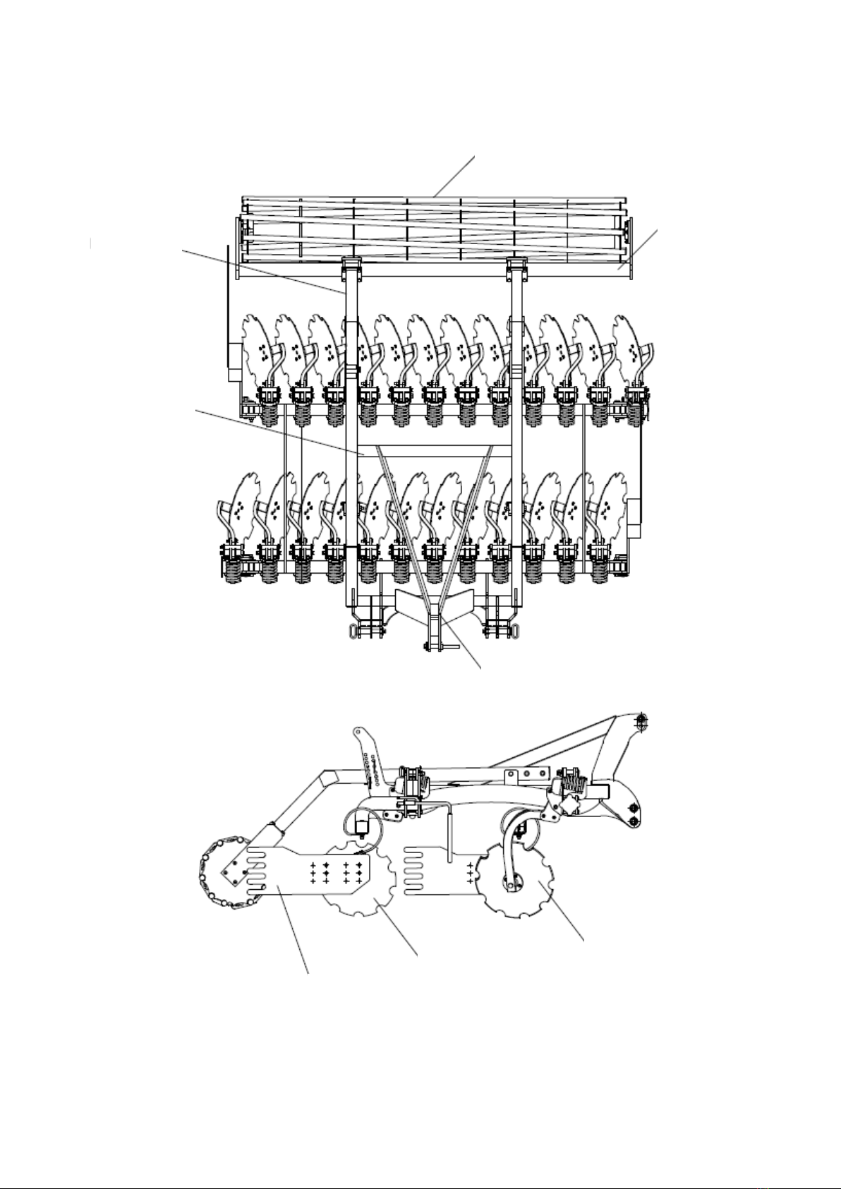
2. Construction of SAL disc harrow
Fig. 2 SAL disc harrow.
Shaft
Shaft
Shaft clamp
Shaft arms
Frame
Drawbar
Side screen
Rear disc row
Front disc row

9
Table 2 Type of SAL disc harrow.
Type of
harrow
Working
width [m]
Number of
discs [pcs.]
Spacing of
disc rows
[mm]
Diameter of
toothed discs
[mm]
Min. tractor
power [HP]
Weight
(kg)
SAL 3.0
3,00
24
1190
610
130
1840
2.1 Purpose of the SAL disc harrow
The disc harrow is designed for post-harvest cultivation (with chopped straw) and
pre-sowing in both ploughing and ploughless technology. The unit can also be used for
mixing catch crops into the soil or cultivating wasteland overgrown with tall volunteer
seeds.
The working elements are toothed discs with a diameter of 620 mm in two
staggered rows, mounted on posts secured by springs. Equipping each disc with its own
maintenance-free bearing allows the disc to be optimally inclined to the direction of
travel and the ground. This allows the stubble to be thoroughly undercut, and harvest
residues to be evenly mixed and broken up. As a result, soil evaporation is interrupted,
plant residues decompose more quickly and there is a reduction in the intensity of
phenolic compounds negatively affecting the development of succeeding plants. The
toothing of the discs aids penetration. The shaft located at the rear of the machine
compacts the soil, resulting in faster emergence of weeds and volunteer seeds. The use
of a disc harrow before sowing ensures thorough mixing of fertiliser into the soil,
levelling of the surface and proper soil structure.
NOTE! The disc harrow is designed exclusively for agricultural use. Use for
any other purpose will be construed as misuse and will void the warranty.
Failure to comply with the recommendations in these operating instructions
will also be construed as misuse.
NOTE! MANDAM provides a guarantee for maintenance-free hubs under the
following conditions:
- comply with the principle of replacing the working discs in the event of
wear, which must not exceed 520mm in diameter for discs Ø620mm,
- use the original MANDAM plates,
- not to exceed the permitted working depth, which is 11cm,
- observe the rule prohibiting the turning manoeuvre with the harrow when
it is in the working position (working discs buried in the soil).
NOTE! The manufacturer is not liable for damage resulting from the
operation of the machine not in accordance with its intended use.
3. General safety rules
The disc harrow may only be started up, used and repaired by persons who are
familiar with its operation and the associated tractor and with the rules of conduct for
the safe operation and handling of the disc harrow. The manufacturer is not responsible
for arbitrary changes to the harrow design. During the warranty period, only factory-
made "MANDAM" parts must be used.

10
The disc harrow should be operated with all precautions in mind, in particular:
•before each start-up, check that the disc harrow and the tractor are in safe
working order,
•use of the machine by minors, persons who are ill or under the influence of
alcohol or other intoxicants is prohibited,
•use work clothes, footwear and gloves when carrying out maintenance work,
•permissible axle loads and transport dimensions must not be exceeded,
•use only original safety and split pins,
•do not approach the disc harrow while it is being raised or lowered,
•it is not permitted to stay between the tractor and the disc harrow when the
engine is running,
•when moving the disc harrow, lift and lower it slowly and gently without sudden
jerks, taking care not to allow any bystanders to be in the vicinity,
•it is forbidden to reverse the tractor or make a U-turn with the machine lowered
into the working position,
•the tractor's independent brakes must not be applied during turning,
•do not stand on the machine or put any additional weight on it during operation or
transport,
•during u-turns, special care should be taken if there are bystanders in the vicinity,
•disc harrows must not be operated on gradients greater than 12°,
•carry out any repairs, lubrication or cleaning of working parts only with the engine
switched off and the machine lowered and unfolded,
•during maintenance and when replacing parts, going inside or underneath the
machine without adequate protection can cause head injuries - a helmet should
be used in this case.
•when not in use, lower the machine to the ground and stop the tractor engine,
•harrows with a working width greater than 3.00 m are fitted with a mechanical
lock to prevent the wings from opening uncontrolled when stationary and during
road transport,
•driving and parking the unit next to a slope with unstable ground may cause a
landslide.
•machinery must be stored in such a way as to prevent injury to people and
animals.
3.1 Proper coupling and uncoupling with the tractor
•The attachment of the machine to the tractor must be made as specified,
remembering to secure the pins and to secure the suspension pins with split pins.
•When coupling the tractor to the disc harrow, it is forbidden for people to stay
between the machine and the tractor during this time.
•The tractor working with the disc harrow must be fully operational. It is forbidden
to couple the harrow with a tractor with defective pneumatic (if the machine has
a braked axle) and hydraulic systems.
•Make sure that the tractor with the attached unit is stable, and the tractor
steerability and stopping power can be maintained. The load on the front axle
cannot drop below 20% of the total load on the tractor axle – set of front-mounted
weights.
•In the resting position, the machine, when uncoupled from the tractor, should
maintain a stable equilibrium.
•The support foot should be rested on a stable surface. It is forbidden to use foot
pads that may cause instability of the support.

11
3.2 Tyres
•Tyre pressures must not exceed those recommended by the manufacturer and it is
forbidden to transport the machine at too low a pressure. This may damage the
machine and cause an accident on large uneven surfaces and when driving too
fast.
•Significantly damaged tyres (particularly profile damage) must be replaced
immediately.
•When replacing tyres, the machine must be secured against rolling.
•Repair work on wheels or tyres should be carried out by persons trained and
authorised for this purpose. This work should be carried out with appropriately
selected tools.
•Each time the wheels are fitted, the tightness of the nuts should be checked after
50km.
3.3 Hydraulic and pneumatic systems
The hydraulic and pneumatic system is under high pressure. All precautions should
be taken, in particular:
•do not connect or disconnect the hydraulic lines when the tractor's hydraulic
system is under pressure (hydraulics set to neutral),
•regularly check the condition of the connections and the hydraulic and pneumatic
hoses.
•the unit must be taken out of service while the hydraulic or pneumatic failure is
being rectified.
3.4 Safety regarding transport on public roads
For transport, the shaft must be folded into the transport position and secured
with pins on a ladder.
During transport, the clearance under the machine should be at least 30 cm
When transporting the unit on public roads, the use of a luminous device, a
distinguishing sign and side reflectors is mandatory.
The travelling speed during transport must not be exceeded:
–on roads with a smooth surface (asphalt) up to 25 km/h,
–on dirt or paved roads 6-10 km/h,
–on bumpy roads not more than 5 km/h.
The driving speed must be adapted to the condition of the road and the conditions
on the road so that the unit does not jump up on the tractor's suspension system. Take
extra care when passing, overtaking and on bends. The permissible operating width of
the machine when travelling on public roads is 3.0 m. It is forbidden to transport the
unit where the slope preceding the aggregate exceeds 7º.
WARNING! Failure to comply with the above rules may create hazards for the
operator and bystanders as well as damage to the machine. Damage resulting from
non-compliance with these rules is the responsibility of the user.

12
In accordance with the road safety regulations (Regulation of the Minister of
Infrastructure of 31.12.2002. Journal of Laws No. 32 of 2002 item 262) – a unit
consisting of an agricultural tractor and the agricultural machinery that is
coupled with it must meet the same requirements as the tractor.
NOTE! The unit as a part of the vehicle protruding beyond the rear side
contour of the tractor obscuring the rear lights of the tractor poses a
danger to other vehicles on the road. It is forbidden to travel on public
roads without appropriate markings.
The manufacturer does not supply warning signs as standard equipment on the machine.
Warning signs are available commercially. The warning boards must be securely mounted
in the brackets and the plug connected to the socket of the tractor's electrical system.
Check the operation of the lights before starting the transport. After lifting the machine,
check the clearance under the lowest working elements, which should be at least 25 cm.
The permissible transport speed of the tractor with the machine is 15 km/h. It should be
reduced to 10 km/h on roads with poorer surfaces and 5 km/h on dirt roads. Extreme
caution should be exercised when passing and overtaking other vehicles, avoiding
obstacles and crossing large irregularities in fields and dirt roads.
3.5 Description of residual risk
Mandam Sp. z o.o. makes every effort to eliminate the risk of accidents. There is,
however, a residual risk that could result in an unfortunate accident. The greatest
danger occurs when:
•using the machine for purposes other than those described in the instructions,
•using the machine by minors, persons who are not authorised, who are ill or who
are under influence of alcohol or other drugs,
•persons and animals within the operating range of the machine are present,
•no caution is paid when transporting and manoeuvring the tractor,
•staying on the machine or between the machine and the tractor while the engine
is running,
•operating and failure to comply with operating instructions,
•driving on public roads.
3.6 Assessment of residual risk
Residual risk can be minimised by applying the following recommendations:
•prudent and unhurried operation of the machine,
•careful reading of operating instructions,
•keeping a safe distance from danger zones,
•prohibition on being on the machine and in the operating area of the machine
while the tractor engine is running,
•carrying out maintenance work in accordance with safety rules,
•use of protective clothing and, if working under machinery, a helmet,
•prevention of unauthorised access to the machines, especially by children.
4. Information on handling and use
Before starting the machine for the first time:
•refer to the operating instructions,
13
•make sure the machine is in good working order,
•check the condition of the hydraulic and pneumatic systems (replace components
if damaged, e.g. pressure lines),
•make sure that the machine's pressure hose couplings fit into the sockets on the
tractor,
•check the tightness of the individual bolts and nuts,
•check the air pressure in the wheels in accordance with the manufacturer's
recommendations,
•ensure that all components requiring lubrication are lubricated,
•ensure that the pressure in the tractor wheels is the same on each axle to ensure
even operation.
4.1 Preparing the disc harrow
The disc harrow is usually delivered to the customer ready for use. However, due
to the limitations of transport facilities, it is also possible to deliver it in a partially
dismantled state - this usually involves disconnecting the shaft.
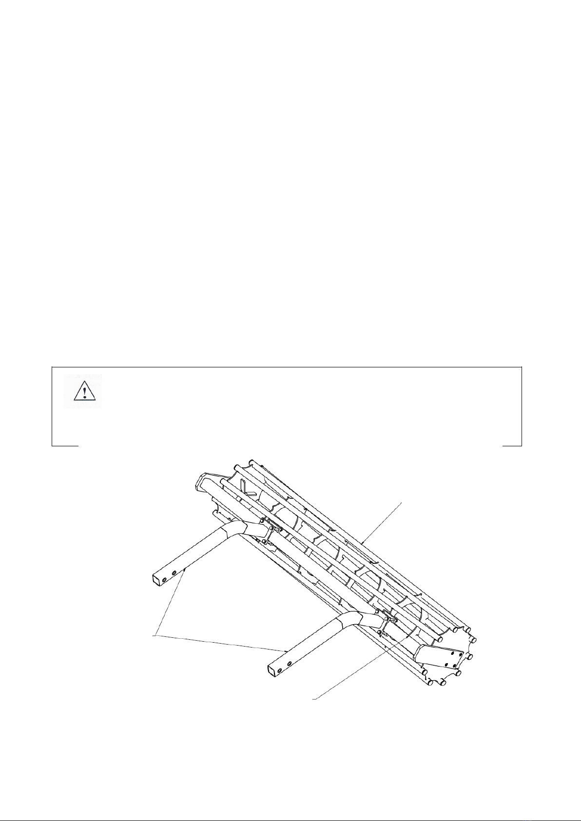
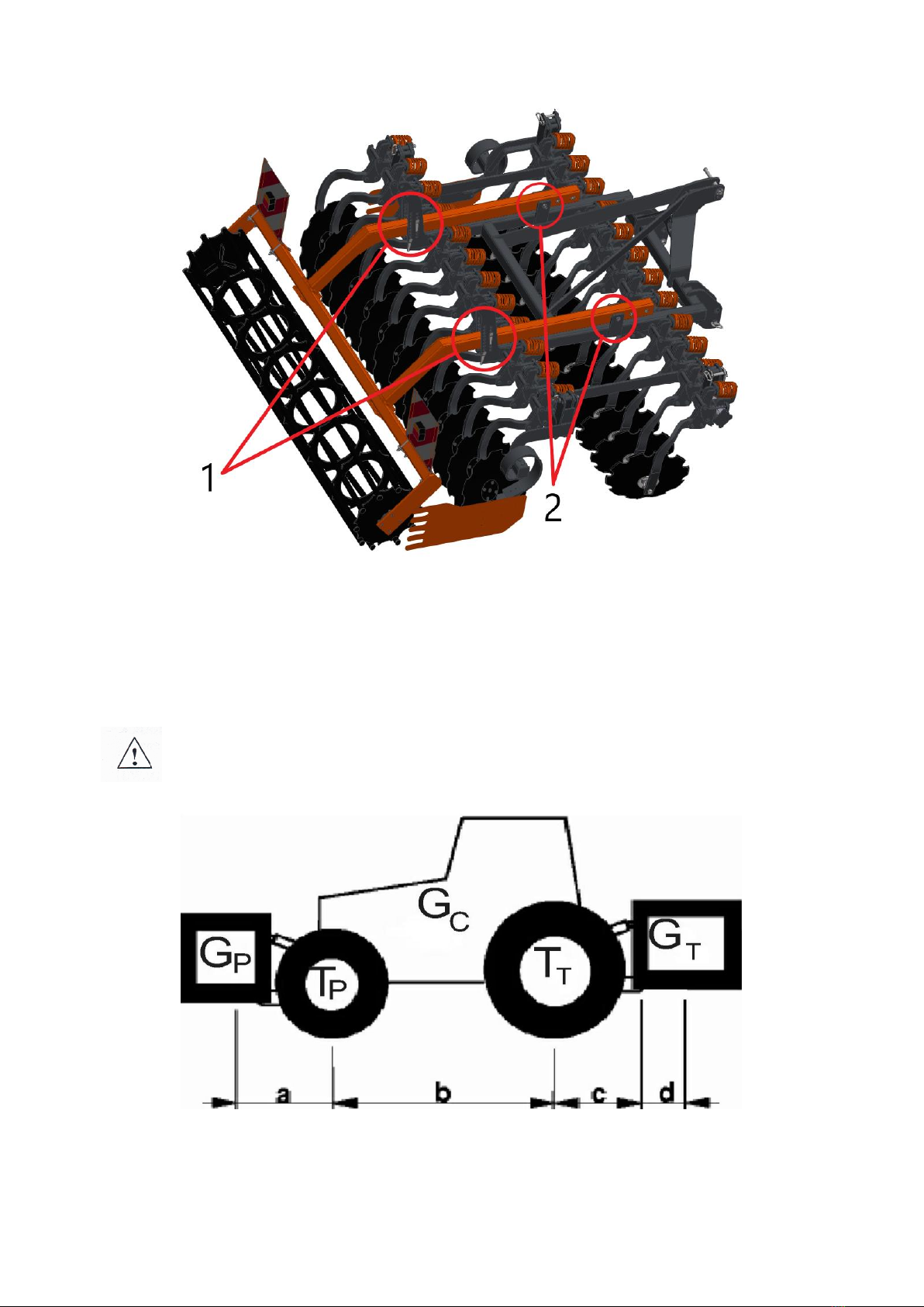
When the unit is first prepared for operation, its components (shaft) must be
assembled. To do this, place the disc harrow on flat paved ground in a position that
allows the shaft to manoeuvre. Use a lifting device to transport the shaft. Position the
arms in the harrow brackets and bolt together at the desired extension (Fig. 4 - No. 1),
then secure the arms with the pins in the ladders while adjusting the desired height
(Fig. 4 - No. 2).
NOTE! The correct procedure for mounting the shafts in the arm holders
requires that the bolts be evenly tightened diagonally, so that the entire
plane of the arm holders is adjacent to the plane of the shaft clamp
profile. This provides the most secure way of connecting the shaft arms to
the machine!
Fig. 3 Connection of the arms with shaft bracket.
Arms
Tubular shaft
Shaft clamp
14
Fig. 4 View of the SAL disc harrow with the fixing points of the roller arms, 1 - pin fixing, 2- bolt + nut
fixing.
Before starting work, check the technical condition of the unit, especially the
condition of the working parts and screw connections.
NOTE! The permissible axle loads and tyre load capacities must not be
exceeded. The load on the front axle must not be less than 20% of the
total load.
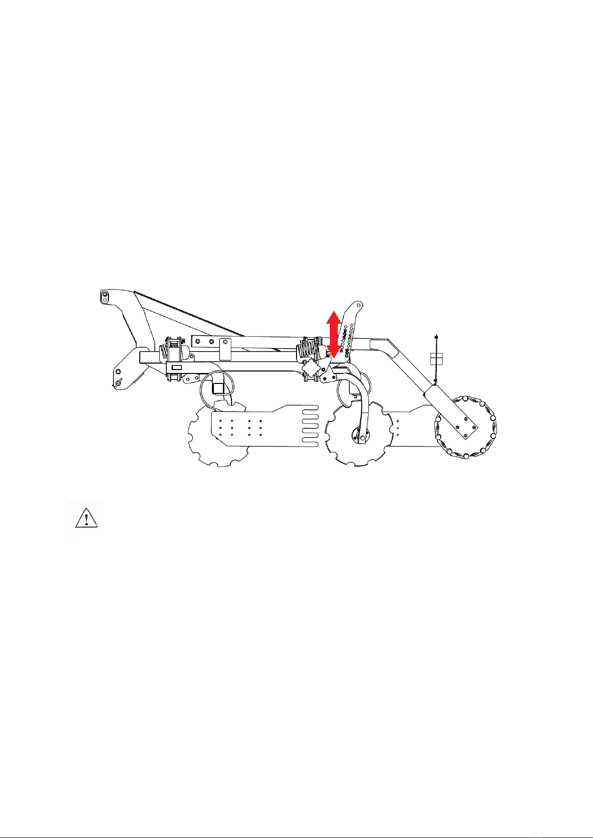
Fig. 5 Diagram of tractor load designations.

15
Axle load calculations
Designations:
GC– tractor weight,
TP– front axle load of the empty tractor,
TT– rear axle load of the empty tractor,
GP– total weight of rear-mounted device,
GT– total weight of front-mounted device,
a – distance between the centre of gravity of the front-mounted device and the centre of the
axle,
b – tractor wheel track,
c – distance between the centre of the rear axle and the centre of the hitch bolt of the
rear device,
d – distance of the machine's centre of gravity from the tractor's hitching pins (for
suspended machines assume 1.4 m, for machines with a seed drill assume 3 m),
x – distance of the centre of gravity from the rear axle (if the manufacturer does not
specify this parameter, enter 0.45).
Minimum load at the front for rear-mounted machine:
Actual front axle load
Actual total weight
Actual rear axle load
4.2 Coupling the disc harrow to the tractor
The tractor wheel tyre pressure should be in accordance with the manufacturer's
recommendations. The lower links of the three-point hitch should be at an equal height,
at a spacing corresponding to the spacing of the lower suspension points. When
connecting the disc harrow to the tractor, the harrow should stand on firm and level
ground.

16
Fig. 6 Three-point suspension system of the tractor's three-point hitch: 1,2 - lower links, 3 - upper
fastener, 4 - left suspension, 5 - right suspension with adjustable length, 6 - lift arm, 7 - lift shaft
When attaching the SAL disc harrow to the tractor, do the following:
•switch the tractor's hydraulic system to position control,
•remove the lower link pins if the tractor's three-point hitch is not equipped with
hitching hooks,
•carefully back up, suspend the machine from the lower links, then secure,
•connect the upper link on the tractor (on units not equipped with a trolley) -
when the unit is running, the attachment point of the upper link on the machine
should be higher than the attachment point of this link on the tractor,
•check the lifting and lowering of the pre-seed unit and the operation of the
hydraulic system.
Any tractor that is used with the machine must be equipped with a set of weights
and must remain steerable during transport, i.e. a minimum of 20% of the tractor's
weight must be on the front axle.
4.3 Coupling the seed drill to the disc harrow
Before suspending the seed drill, familiarise yourself with the weight of the drill
including the seed. The load capacity of the hydropack is 1,300 kg. When coupling the
seed drill to the disc harrow, do the following:
•match the spacing of the towing hooks to the spacing of the seed drill pins by
placing a hook on the appropriate side of the arm and shimming the spacer plate
accordingly,
•lower the lower links of the hitch below the hitching pins of the seed drill (in the
case of a trolley hitch, insert a pin into the appropriate hole in the hangers of the
hitch, then adjust the position with a cylinder),
•reverse the set so that the seed drill pins are in the hooks,
•insert the safety device into the pins, hole in the hooks and secure with a safety
pin,
•connect the top link to the seed drill.
NOTE! Before raising the disc harrow, the seed drill must be raised for the
stability of the unit.
17
4.4 Operation and adjustment
On the SAL disc harrow, the position of the individual working units must be
preadjusted before starting work in the field. It is also necessary to level the machine
longitudinally with the tractor's top link and transversely with the lower link hanger. The
first working run should then be made to set the optimum working speed and correct the
adjustment based on an assessment of the correct operation of the individual units. The
working speed should be 10 - 15 km/h. In a well-adjusted machine, the frame must be
parallel to the ground and all working units should penetrate the soil equally across the
entire working width.
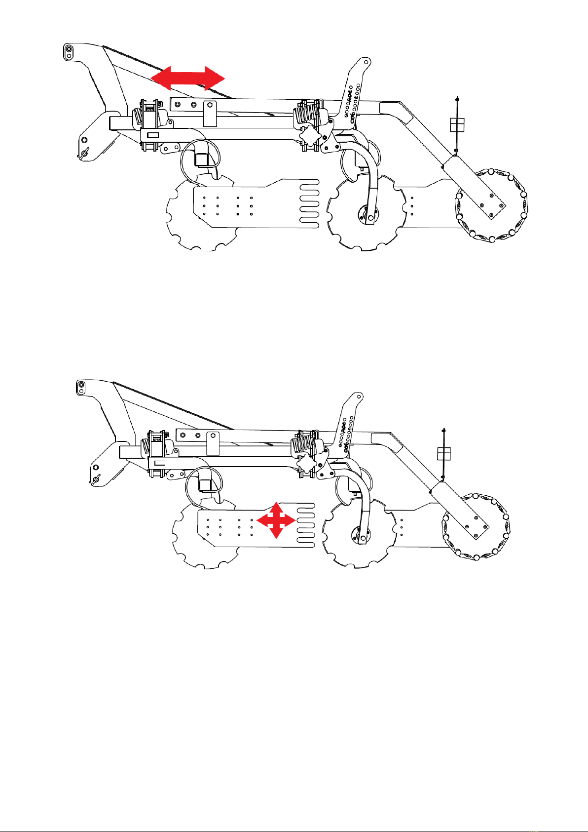
4.4.1 Adjusting the shaft position
The position of the shaft can be adjusted in 2 ways, changing its offset from the
discs and the working depth, these are described below:
The working depth is determined by locking the shaft arms using locating pins
with locating plates on the ladder at the desired height. Particular care must be taken to
ensure that the pins are fitted equally on both sides.
Fig. 7 Adjusting the working depth of the shaft.
Caution ! When setting the working depth, take into account the sinking of
the shaft into the ground depending on the condition of the surface and
the type of crop.
Distance of the shaft from the discs - extend the unlocked arms to the desired
distance and then secure with screws on the handle. However, it must be remembered
that moving the shaft backwards causes the machine to lengthen and worsens the
longitudinal balance of the tractor.
18
Fig. 8 Adjusting the shaft offset from the discs.
4.4.2 Setting up side screens
The side screen should be positioned and locked with screws at such a height that
the screen is above the soil surface and not exposed to the impact of stones and the
hanging of crop residues. If required, it should also be moved forwards or backwards
(remounting on the holes) so that it retains the soil rejected by the outermost front disc
and rakes the furrow behind the outermost rear disc.
Fig.9 Setting up side screens
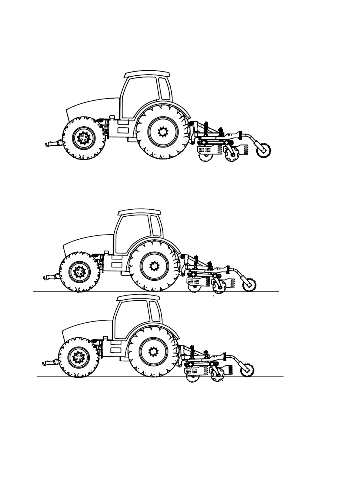
4.4.3 Setting up the work units
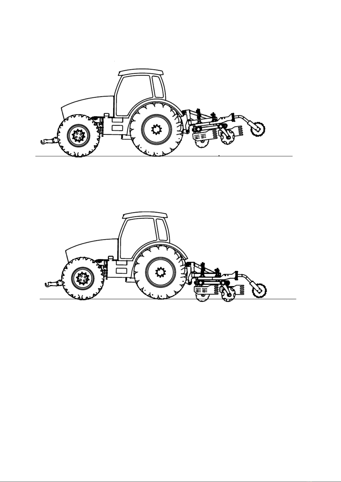
Setting up the machine correctly for operation
The machine must be set up parallel to the ground for operation (see Fig.10). The front
drawbar should be aligned horizontally. It is forbidden to operate the machine with the
drawbar at an angle!
19
Setting up the machine correctly for operation:
Fig. 10 Properly positioned machine parallel to the ground.
Incorrect machine settings:
Fig. 11 Incorrect machine settings.
Turning at field ends is only permitted with the machine raised on the chassis.
Correct operation
Incorrect operation
20
Turning the machine correctly:
Fig. 12 Turning the machine correctly.
Turning with the machine buried in the spoil in or turning on shafts is not permitted:
Fig. 13 Turning the machine incorrectly.
When working with the machine, it is also advisable to use an additional weight on the
front of the tractor to enable more stable and comfortable working.
Correct turning
Incorrect turning
Table of contents
Other Mandam Farm Equipment manuals

Mandam
Mandam MGP Series User manual

Mandam
Mandam BTH-D User manual

Mandam
Mandam MBS User manual

Mandam
Mandam ORKAN VARIO Series User manual

Mandam
Mandam MWC Series User manual

Mandam
Mandam ORKAN 3+ User manual

Mandam
Mandam SUPER User manual

Mandam
Mandam MGX 2200 User manual

Mandam
Mandam Hybro 3,0 User manual

Mandam
Mandam MCH Series User manual


Popular Farm Equipment manuals by other brands


MacDon
MacDon D1XL Series Assembly instructions

Checchi & Magli
Checchi & Magli UNITRIUM owner's manual

Amity Technology
Amity Technology Crop Chaser 1000 operating manual

GREAT PLAINS
GREAT PLAINS Yield-Pro PL5800 Operator's manual

Spudnik
Spudnik 8060 parts manual

LELY
LELY Splendimo Triplo 801 Operator's manual


