Mandam BTH-D User manual

1
MANDAM Sp. z o.o.
ul. Toruńska 14 44-100 Gliwice, Poland
e-mail: [email protected]
Tel.: 032 232 26 60 Fax: 032 232 58 85
NIP (VAT no.): 648 000 16 74 REGON (Registration no.): P – 008173131
INSTRUCTION MANUAL
HYDRAULIC DISC HARROW
with BTH-D drawbar
Issue II
Gliwice 2022

2
DECLARATION OF CONFORMITY
FOR A MACHINE
In accordance with the Ordinance of the Minister of the Economy dated 21 October 2008 (Journal of Laws No. 199, item
1228)
and the Directive of the European Union no. 2006/42/EC of 17 May 2006
MANDAM Sp. z o.o.
ul. Toruńska 14
44-100 Gliwice
hereby declares at its sole responsibility that the following machine:
under this declaration, complies with:
the Ordinance of the Ministry of Economy of 21 October 2008 on fundamental
requirements for machinery (Journal of Laws No. 199, item 1228)
and the Directive of the European Union 2006/42/EC of 17 May 2006.
The persons responsible for the technical documentation for the machine: Jarosław Kudlek, Łukasz
Jakus
ul. Toruńska 14, 44-100 Gliwice, Poland
For assessment of compliance the following standards have been applied:
PN-EN ISO 13857:2010
PN-EN ISO 4254-1:2016-02
PN-EN ISO 12100-1:2005/A1:2012
PN-EN ISO 12100-2:2005/A1:2012
PN-EN 982+A1:2008
This EC Declaration of Conformity shall be cancelled
if the machine is modified or redesigned without consent of the manufacturer.
………………………………………
………………………………………
Place and date of issue
First and last name, position held
and signature of the person authorized
BTH disc harrow with BTH-D drawbar
type/model: ……………………………...
year of manufacture: …………………….
serial number: ……………………………
VIN: ………………………………………

3
1. Introduction................................................................................................................................4
1.1. Safety symbols and inscriptions ...........................................................................................6
2General information ..................................................................................................................8
2.1. Design of the BTH disc harrow with BTH-D drawbar.......................................................8
2.2. Intended use of the BTH disc harrow with BTH-D draw...................................................9
3General safety information .....................................................................................................10
3.1. Proper hitching and unhitching of the harrow with/from the tractor .............................11
3.2. Tyres....................................................................................................................................11
3.3. Hydraulic and pneumatic systems .....................................................................................11
3.4. Brake system .......................................................................................................................13
3.4.1 Dual-circuit hydraulic brake.....................................................................................13
3.4.2 Automatic brake valve with spring brake – 206613 ...............................................13
3.5. Hydraulic system quick couplings .....................................................................................20
3.6. Transport safety on public roads........................................................................................21
3.7. Residual risk description ....................................................................................................22
3.8. Residual risk assessment ....................................................................................................22
4Information on operation and use ..........................................................................................22
4.1. Preparation of the disc harrow ..........................................................................................24
4.2. Hitching the harrow with the tractor.................................................................................25
4.3. Hitching the sower with the disc harrow...........................................................................26
4.4. Operation and adjustment..................................................................................................26
4.4.1 Automatic locking of the machine side extensions..................................................26
4.4.2 Implement opening sequence ....................................................................................27
4.4.3 Working depth of the BTH disc harrow with BTH-D drawbar ............................29
4.5. Rules for transporting the harrow on public roads and lighting the implement .............32
4.6. Maintenance and lubrication.............................................................................................34
4.7. Screw tightening torque .....................................................................................................35
5Maintenance of the BTH disc harrow with BTH-D drawbar..............................................36
6Replacement procedures .........................................................................................................38
7Storage of the disc harrow.......................................................................................................39
8Disassembly and withdrawal from service and scrapping ...................................................40
9Spare parts for the BTH disc harrow with BTH-D drawbar...............................................40
4
1. Introduction
Congratulations on your purchase of the BTH disc harrow with BTH-D drawbar.
This instruction manual contains the information on hazards that may occur during
operation, work with the device, technical data and the most important guidelines and
recommendations to be known and applied to ensure a proper operation. Keep this manual
for future reference. Should you have any problems with understanding any statement in
the instruction manual, please contact the manufacturer.
The following mark indicates the guidelines that are important due to safety reasons:
Machine identification
Identification data of the BTH disc harrow, including basic information on the
manufacturer and the machine and CE marking, can be found on the rating plates placed
on the load-bearing frame:
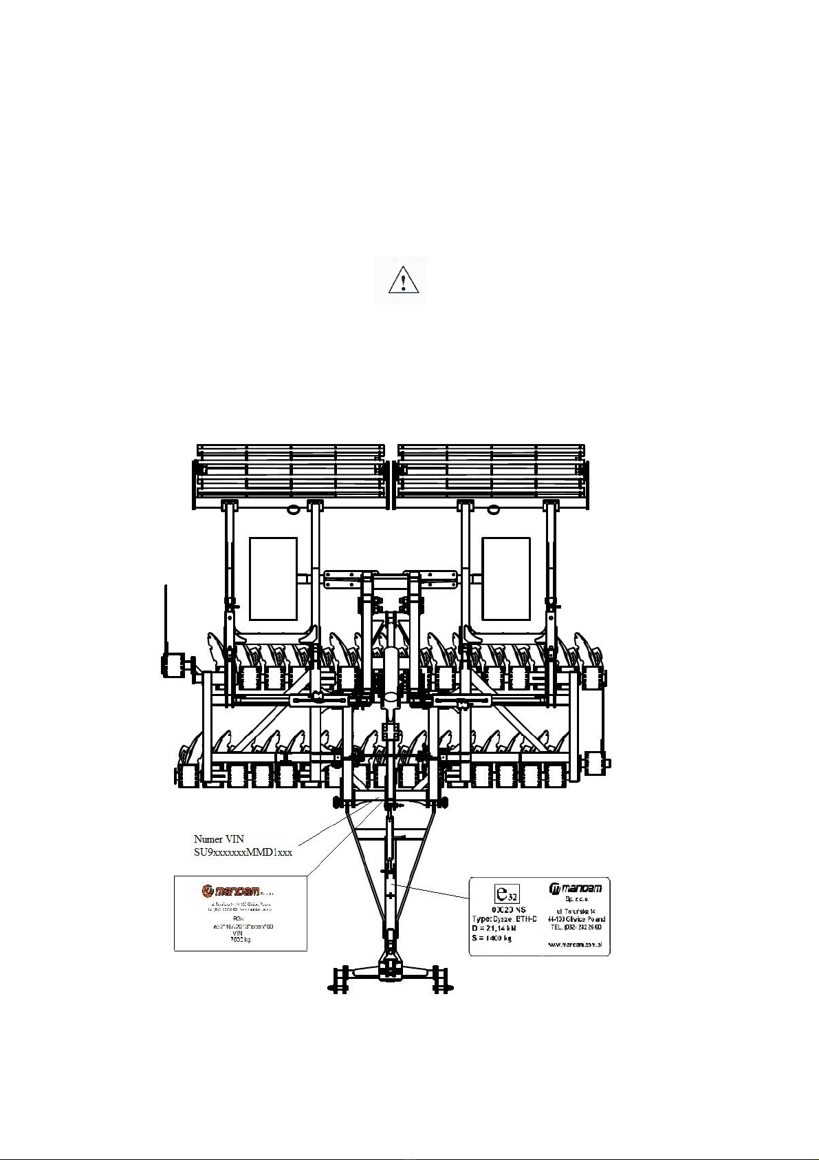
Fig. 1 View of the harrow with location of markings.
5
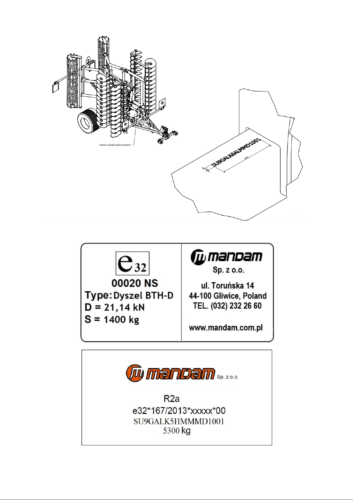
Fig. 2 Location of VIN placed on the machine.
Fig. 3 Rating plate of the BTH disc harrow.

6
The warranty for the harrow is valid for 12 months from the date of sale.
The warranty card constitutes an integral part of the machine.
Whenever you request any information on spare parts, provide the serial number.
For more information on spare parts,
•please visit our website at: http://mandam.com.pl/parts/
•call us at +48 668 662 289
•e-mail us at: [email protected]
1.1. Safety symbols and inscriptions
CAUTION! Special care must be taken when using the implement in case of
areas marked with special information and warning signs (yellow stickers).
The following symbols and inscriptions can be found on the implement. Secure the
symbols, signs and inscriptions against loss and make sure they are legible at all times. If
lost and illegible, replace the symbols, signs and inscriptions with new ones.
Table 1. Information and warning signs.
Safety sign
Meaning of the safety sign
Location on the implement
Read the instruction manual
prior to operating the
implement.
Frame adjacent to the
mounting place of the upper
fastener
Danger of toe or foot crush
Frame adjacent to the
mounting place of the upper
fastener

7
Safety sign
Meaning of the safety sign
Location on the implement
Keep clear from lift bars
while controlling the lift
Frame adjacent to the
mounting place of the upper
fastener
Keep clear from foldable
and moving parts of the
implement
Front part of the central
frame adjacent to side
frames
Do not reach into the
crushing zone if the
elements can move
Central frame adjacent to
side frames
Pressurized fluid – hazard of
bodily injury
Cylinders
Fixing point for transport
belts
Upper part of the drawbar
(upper fastener bolt)
Rear part of the frame:
•rigid frame (adjacent
to the roller depth
adjustment)
•foldable frame
(adjacent to the
cylinder bolt on the
central frame)

8
2 General information
2.1. Design of the BTH disc harrow with BTH-D drawbar
The harrows are available in the following widths: 4.0 m, 5.0 m, 6.0 m, and 8.0 m.
Fig. 2 BTH disc harrow with BTH-D drawbar.

9
Table 2. BTH disc harrow types.
Harrow type
Working
width [m]
Tined disc
diameter [mm]
Number of discs
[pcs]
Min. tractor
power [hp]
Wheel size
GAL-K 4.0H
4
560
32
150
480/45-17”
GAL-K HD 4.0H
610
GAL-K 5.0H
5
560
40
180
480/45-17”
GAL-K HD 5.0H
610
GAL-K 6.0H
6
560
48
200
480/45-17”
GAL-K HD 6.0H
610
TAL-K 4.0H
4
560
32
150
620/40-22.5”
TAL-K 5.0H
5
560
40
180
620/40-22.5”
TAL-K 6.0H
6
560
48
200
620/40-22.5”
TAL-K 8.0H
8
560
64
220
620/40-22.5”
SAL-K 6.0H
6
610
48
220
620/40-22.5”
2.2. Intended use of the BTH disc harrow with BTH-D draw
The disc harrow is designed for post-harvesting (with crushed straw) and pre-sowing
cultivation in both plough and ploughless technology. The implement can also be used for
mixing aftercrop or uncultivated land with high self-sown plants with soil.
The working elements are tined discs with the diameter of Ø610 mm and Ø560 mm
in two shifted rows mounted on maintenance-free bearings. Equipping each disc with its
own bearing allows for an optimum inclination of the disc in relation to the direction of
travel and the ground. This allows the stubble to be accurately cut and ensures that the
post-harvesting crop residues are evenly mixed and ground. As a result, evaporation of the
soil is interrupted, plant residues decompose more quickly and the intensity of phenolic
compounds, which have a negative impact on the development of successive crops, is
reduced. Disc tines help to penetrate the ground. Rollers at the rear of the implement
compact the soil, resulting in faster germination of weeds and self-sown plants. The use
of a disc harrow before sowing ensures a precise mixing of fertilisers with the soil, an even
surface and an appropriate soil structure.
The harrow can also be equipped with a hydropack for coupling with a sower.
BTH implements with a BTH-D drawbar are (optionally) equipped with their own driving
system with a braked axle. The pneumatic system is used for this purpose.
CAUTION! MANDAM grants a 5-year warranty on maintenance-free hubs
subject to the following conditions:
- the principle is observed of the working disc replacement in case of their
wear which may not exceed the diameter of 490 mm for Ø560 mm discs,
and 550 mm for Ø610 mm discs,
- original MANDAM discs are used,
- the permissible working depth, which is 12 cm for Ø560 mm discs and 15
cm for Ø610 mm discs, is not exceeded,
- the principle is observed of no turning manoeuvre of the harrow when it is
in the working position (working discs recessed in the soil).

10
CAUTION! The disc harrow is designed for agricultural use only. Using the
implement for tasks that differ from the intended use shall be regarded as
misuse, resulting in loss of warranty. Failure to follow the guidelines included
in this instruction manual shall be regarded as misuse.
CAUTION! The manufacturer shall not be liable for any damage arising out of
misuse.
3 General safety information
The disc harrow can be started, operated and repaired only by persons familiar
with its operation and with the operation of the attached tractor as well as knowing the
rules of safe operation and maintenance of the implement.
The manufacturer shall not be liable for any unauthorised alternation of the harrow. Only
genuine MANDAM spare parts shall be used during the warranty period.
The disc harrow must be operated with all precautionary measures and due care, in
particular:
•before every start-up check the disc harrow and the tractor, make sure that their
conditions guarantee safety of traffic and operation;
•minors, disabled or intoxicated persons (under the influence of alcohol or drugs)
must not operate the machine,
•during operation and maintenance wear working clothes, footwear and gloves,
•do not exceed the maximum axle loads and transport dimensions,
•use only original cotter pins and pins,
•do not approach the disc harrow while it is being lifted or lowered,
•do not stay between the disc harrow and the tractor when the engine is running,
•drive away with the implement, lift and lower it slowly and smoothly, without
jerking, making sure no outsiders are in the area,
•do not reverse and make U-turns when the implement is lowered to the working
position,
•when making U-turns do not use independent tractor brakes;
•during the operation and travel do not stand on the implement and do not put
additional loads onto it;
•while making U-turns, pay due caution if anyone is in the vicinity,
•never use the disc harrow on slopes with the inclination exceeding 12°,
•any repairs, lubrication or cleaning of working components may be performed as
long as the engine is not running and the implement is lowered and unfolded,
•there is a hazard of head injury when you perform maintenance or replacement of
parts in or under the implement without adequate protection – wear a hardhat,
•during a break in the work, always lower the implement to the ground and stop the
tractor engine,
•the harrow with the working width exceeding 3.00 m is equipped with an automatic
locking device that blocks the side extensions from uncontrolled opening during
standstill and road travel,
•driving and parking the implement on an unstable slope may cause soil slipping,
•store the implement in a manner preventing injury to people and animals.

11
3.1. Proper hitching and unhitching of the harrow with/from the
tractor
•Hitch the implement with the tractor according to the recommendations, use pins
and protect the suspension pins with cotter pins.
•When hitching the disc harrow, do not stay between the tractor and the attached
implement.
•The tractor used together with the disc harrow must be fully functional and in good
working order. It is forbidden to couple the machine to any tractor with a
malfunctioning pneumatic system (if the machine has a braked axle) and hydraulic
system.
•Remember to observe the following: balance of the tractor and the suspended
implement, tractor steerability and braking performance – the front axle load must
not drop below 20% of the total tractor load – a kit of front weights;
•When in resting position and disconnected from the tractor, the machine must be
stable all the time.
•Place the support leg on a stable ground. Do not use pads under the leg as this may
cause instability.
3.2. Tyres
•Tyre pressure cannot exceed the value recommended by the manufacturer.
Transporting the implement when the pressure is too low is prohibited. This may
cause damage to the implement or an accident when travelling too fast and on very
uneven surfaces.
•Considerably damaged tyres (particularly the tyre profile) must be replaced
immediately.
•Protect the implement from rolling away when replacing the tyres.
•The repair works on wheels or tyres must be performed by persons trained and
authorised for this purpose. Such works must be performed with properly selected
tools.
Following every assembly of wheels, check the tightening of nuts after travelling the
distance of 50 km.
3.3. Hydraulic and pneumatic systems
The hydraulic and pneumatic systems are pressurised. Take all precautionary measures,
in particular:
•do not connect and disconnect hydraulic hoses when the tractor hydraulic system is
pressurised (hydraulics set to neutral),
•regularly check the hydraulic and pneumatic connections and hoses;
•do not use the implement until the hydraulic or pneumatic system is repaired.
12
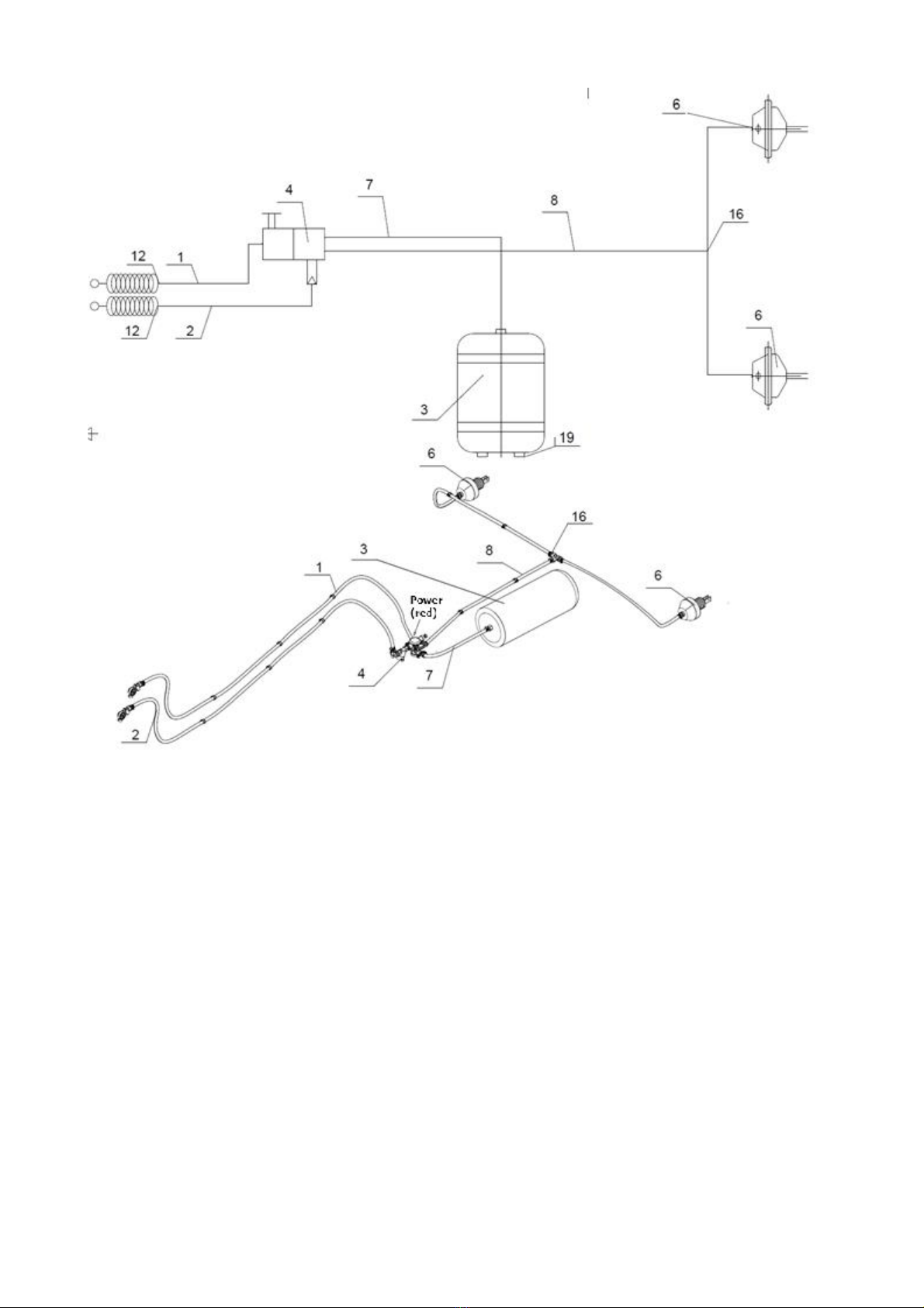
Fig. 3 Pneumatic diagram of BTH harrow with BTH-D drawbar: 1 – spiral wire connector (red), 2 – spiral
wire connector (yellow), 3 – 40L air tank, 4 – agricultural trailer control valve, 6 – 24” diaphragm actuator,
7-8 – rubber airline, 12 – adapter, 16 – M22 tee, 19 – tank plug.
13
3.4. Brake system
3.4.1 Dual-circuit hydraulic brake
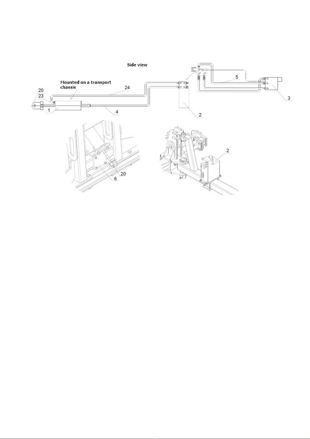
Fig. 4 Diagram of the dual-circuit hydraulic brake with key working components of the BTH harrow with
the BTH-D drawbar: 1 – combination brake cylinder, 2 – valve with pump tank, 3 – DLC- dual-line quick
coupling with cable, 4-5 – hydraulic line, 6 – hydraulic cylinder mounting plate, 20 – bar handle, 23 – elbow
connector, 24 – hydraulic line.
3.4.2 Automatic brake valve with spring brake – 206613
The SAFIM valve on the machine is designed to manage the service and emergency
braking functions of the dual-circuit hydraulic braking system. If the trailer is
disconnected from the tractor, the automatic brake valve engages the emergency
braking function. This function is achieved by using the energy previously stored on the
compressed spring of the SAHR actuators which become active when the oil of the spring
brake section is discharged into the tank.

14
Fig. 5 An overview view of the dual-line hydraulic braking system.
Fig. 6 Valve with marked components.
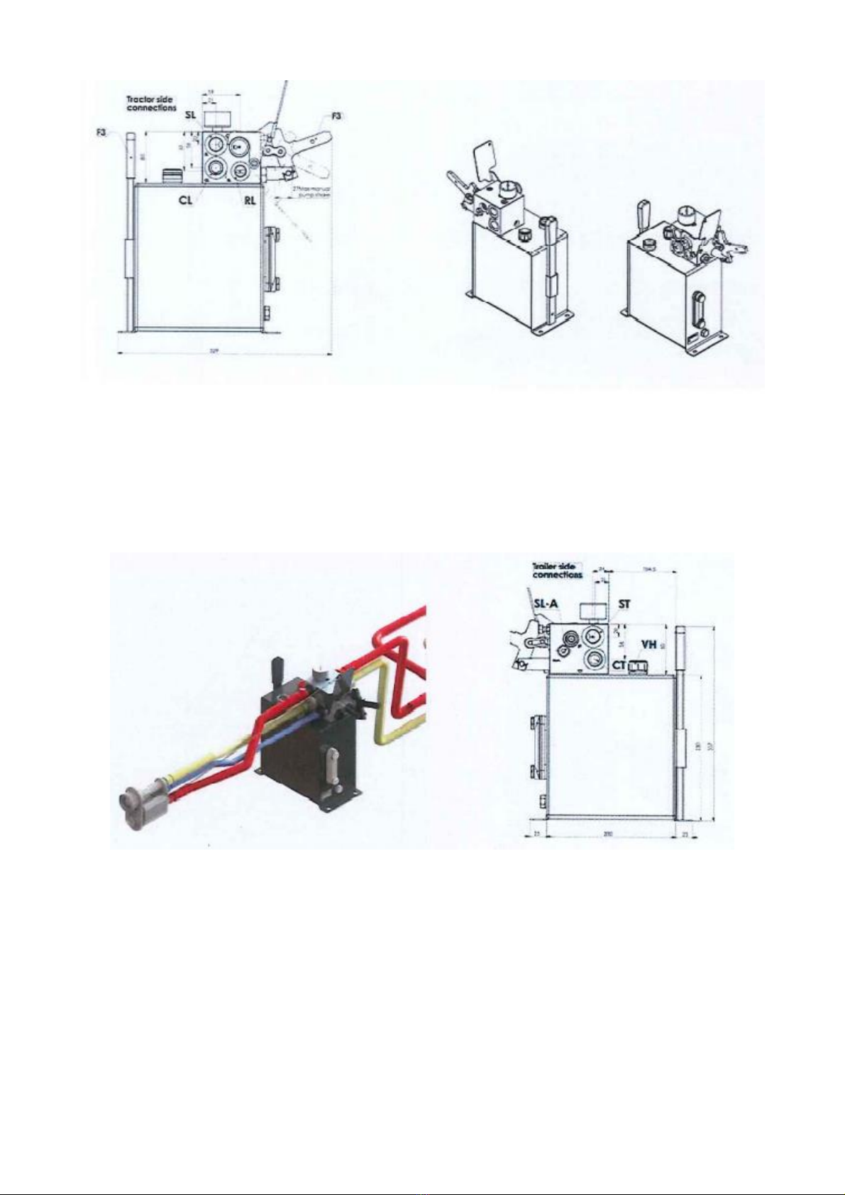
Figures 7 and 8 show the corresponding valve plans, along with the designations of the
most important wires and connectors, where they denote sequentially:
•CL – control line (from the coupling joint),
•SL – secondary line (from the coupling joint),
•RL – return line (from the coupling joint),
15
Fig. 7 A plan showing the joints from the tractor side.
•CT – output port (of brake actuators or load sensing valve, if installed),
•ST – output port (of spring brake sections of connected SAHR actuators – SL port),
•SL-A – return line from the automatic load sensing valve, if installed.
Fig. 8 A plan showing the joints from the disc harrow side.
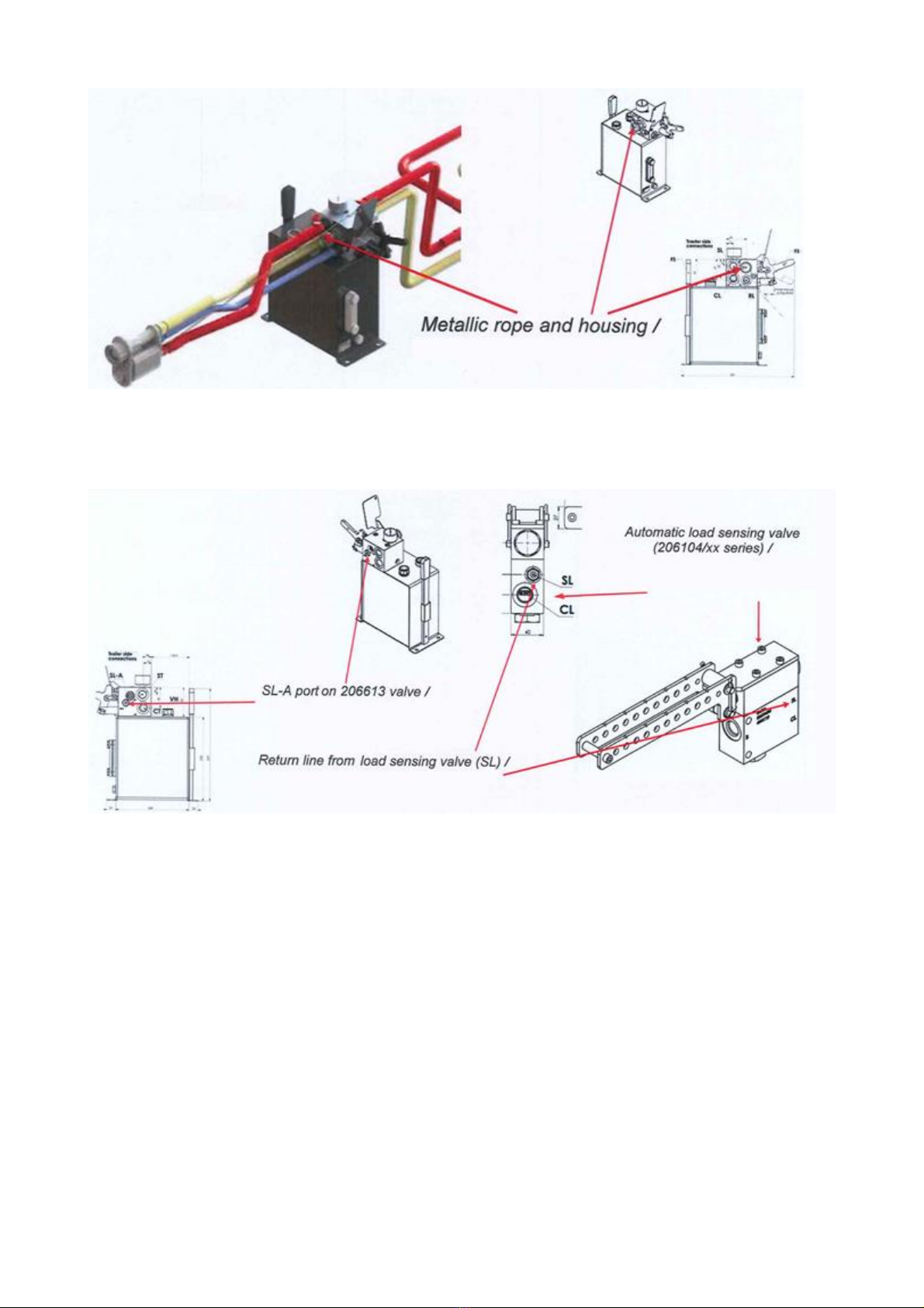
It is important to remember that during installation, the metal rope (pre-installed on
the coupling joint) must be connected to its dedicated housing on the valve. Also make
sure that the length of the cables is 20-30 cm shorter than the length of the hydraulic
lines.
16
Fig. 9 Marking the connection point of the metal rope to its dedicated housing.
If the braking system includes an automatic load sensing valve of type 206104/xx,
connect the SL-A port of the automatic brake valve to the SL port of the load sensing
valve.
Fig. 10 Marking the place of connection when using automatic load sensing valve type 206104/xx.
The brake valve has several modes of operation. All modes are listed below, along with
their descriptions:
Mode 1 – Travel mode:
•Dual-line connector: connection to tractor
•Tractor engine: on
•Parking brake: released
The activation spool automatically returns to the travel mode position when the
pressure in the secondary line (SL) increases to its normal value.
The valve’s normal function mode is engaged whenever the operator connects the dual-
line connector, turns on the tractor engine and releases the parking brake.
The device provides all standard trailer braking functions when the driver brakes. If the
trailer is disconnected from the tractor, the automatic brake valve engages the
automatic emergency braking function.

17
Fig. 11 Standard position of the activation spool in the travel position.
Mode 2 – Emergency mode:
When the trailer is disconnected from the tractor, an automatic brake valve connects
the spring brake section of the SAHR cylinders to the tank. The oil holding the springs
under tension is discharged into the tank, the spring action activates the emergency
brake function.
The automatic emergency brake function is activated even if the pressure in the
secondary line (SL) drops while the DLC is still connected to the tractor. The activation
spool remains in its normal function position when the automatic brake function is
activated.
Mode 2a – Parking mode:
In a spring brake trailer braking system, the application of the automatic emergency
braking function overlaps with that of the parking brake, since spring brakes generate
both functions. Therefore, disconnecting the DLC connector ensures that the vehicle is
properly parked.
If the operator disconnects the double-line connector from the tractor, it is
recommended to connect it to the dummy connection of the valve housing to avoid
contamination.

18
Fig. 12 Port of dummy connection of the remaining coupling joints.
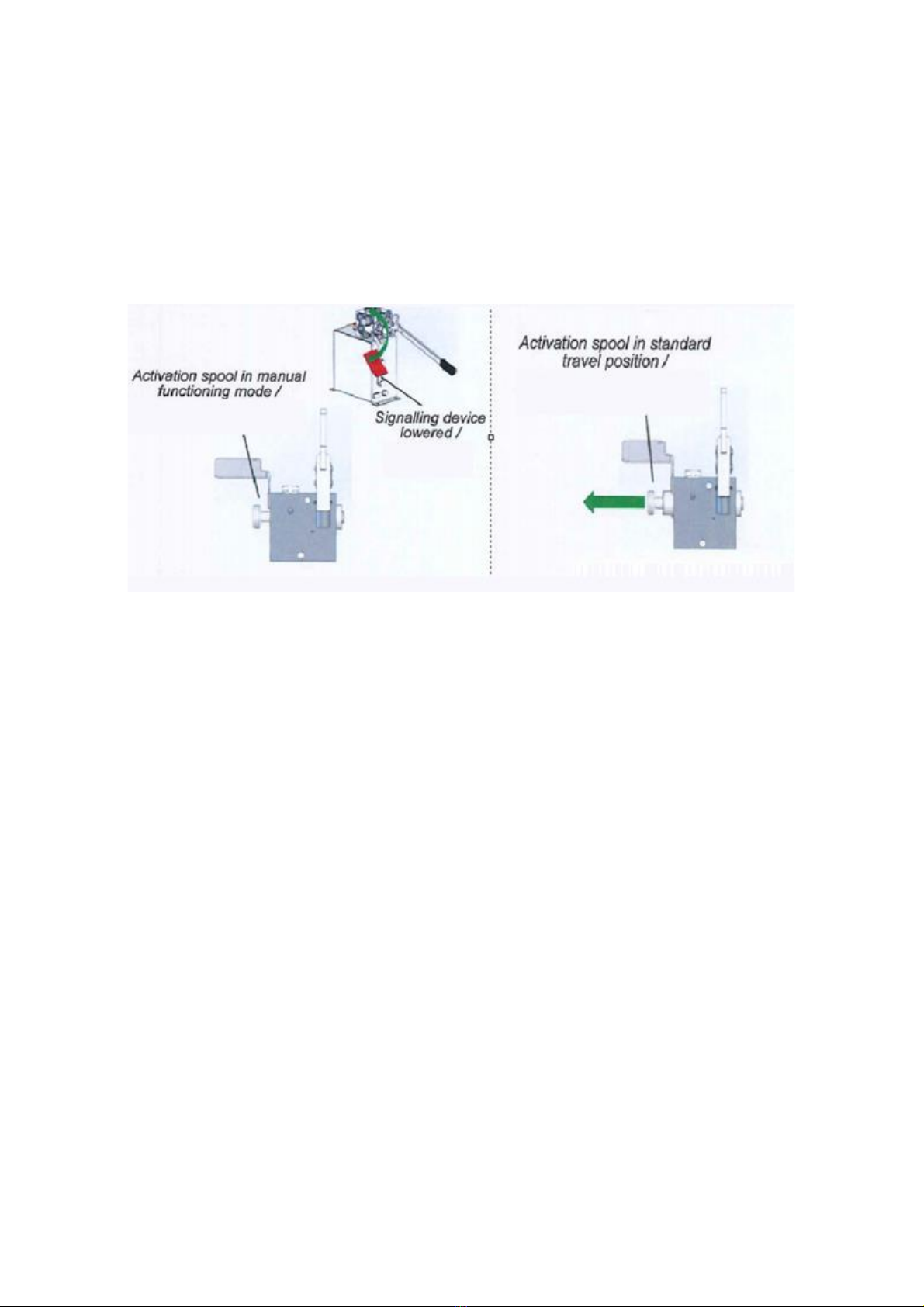
Mode 3 – Removal of the automatic brake function:
To remove the automatic brake function (if towing a trailer by a non-double-line tractor
or other type of vehicle):
•Press the activation spool (as in the image on the right)
until it is fully extended. The signalling device will move
downward generating the activation of manual mode
operation;
•Pump oil from the tank into the spring brakes using a
manual pump. The auto/parking brake function will be
disabled.
NOTE: the brakes will be released when the pressure in the SL
toward the spring section of the SAHR actuators is more than
15 bar. When pumping, check the pressure gauge to ensure
that it indicates the correct pressure not exceeding 35 bar.
NOTE: whenever the activation spool is in “manual
operation/functioning mode”, automatic activation of the
parking brake is not ensured. If the vehicle needs to park
again, check that the activation spool is in the “standard
travel position”.
Mode 4 – Reconnecting to the tractor:
The activation spool automatically returns to its normal function position whenever the
19
pressure in the secondary line (SL) increases to its normal value.
The valve’s normal function mode is engaged each time the operator connects the dual-
line connector, turns on the tractor engine and releases the parking brake. In this
situation, all emergency functions are switched on.
Place the signalling device back to its travel position before turning on the tractor
engine and before releasing the tractor’s parking brake. If the spool is already in the
travel position, it will be impossible to reset the signalling device.
Fig. 13 Positions of the activation spool in the manual functioning position and the standard travel
position.
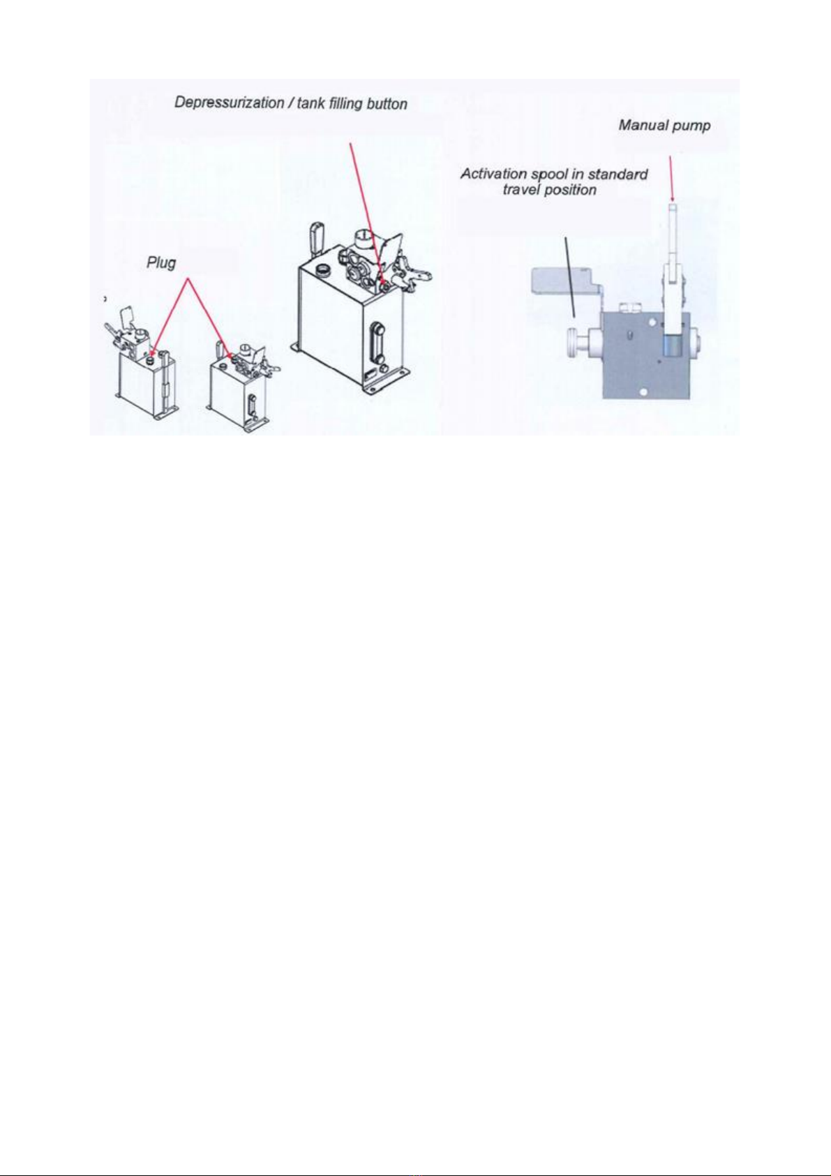
Two alternative procedures are allowed for filling the installation’s oil tank after
installation. To this end:
•Unscrew the oil plug from the top and fill the tank with the correct amount of
oil*;
•Press the “depressurisation/tank filling” button from the front side of the valve
and, keeping it in the same position, slightly depress the tractor’s brake pedal
(this procedure requires two operators, one to operate the tractor and the other
to operate the valve). The oil coming from the tractor through the control line
(CL) will be redirected to the tank. When the oil level is correct, release the
“depressurisation/tank filling” button.
*Use SAE 10W30 compliant oil or that used to fill the tractor’s oil tank
20
Fig. 14 Location of tank plug, depressurisation button and manual pump.
Check the oil level in the tank regularly: the level must always be between the “max”
and “min” positions on the oil level gauge.
If the oil level is below the minimum, follow one of the previously described procedures
to refill the tank.
If the oil level is above the maximum, use the manual pump when the trailer is
connected to the tractor (the activation spool is in the “normal function position”). Oil
will flow from the tank to the tractor’s tank through the secondary line (SL).
If it is difficult to reconnect the tractor’s dual-line connector because of the
pressure remaining inside the lines, it is possible to unload the pressure by pressing the
depressurisation button for a few seconds. This can happen when the vehicle is left
parked in the sun for some time. Excess oil will be drained into the tank and the DLC
joint can be connected again.
The depressurisation button can be pressed with tools such as a screwdriver, wrench
or lever to the manual pump supplied with the valve assembly kit.
3.5. Hydraulic system quick couplings
The machine’s hydraulic system has quick couplings for quick and easy connection of
lines, hoses and the remaining parts of the hydraulic system. Each quick coupling has its
own designation (Fig. 15):
Table of contents
Other Mandam Farm Equipment manuals

Mandam
Mandam MBS User manual

Mandam
Mandam MWC Series User manual

Mandam
Mandam SPEC HD 2,5 User manual

Mandam
Mandam MGX 2200 User manual

Mandam
Mandam KNIFE ROLLER 3.0 User manual

Mandam
Mandam Hybro 3,0 User manual

Mandam
Mandam GAL-K User manual

Mandam
Mandam MCH Series User manual

Mandam
Mandam GAL-C User manual

Mandam
Mandam ORKAN VARIO Series User manual


