Mandam MWC Series User manual

1
P.P.H. MANDAM Sp. z o.o.
ul. Toruńska 2 44-100 Gliwice, Poland
e-mail [email protected]
Tel.: 032 232 26 60 Fax: 032 232 58 85
NIP (VAT no.): 648 000 16 74 REGON (Registration no.): P –008173131
INSTRUCTION MANUAL
MWC/MWW CAMPBELL ROLLER
1.5. 2.5. 3.0; 4.0H 6.0H
Issue II
Gliwice 2014

2
EC DECLARATION OF CONFORMITY
FOR A MACHINE
Pursuant to the Ordinance of the Ministry of Economy of 21 October 2008
(Journal of Laws No. 199, item 1228)
and the Directive of the European Union no. 2006/42/EC of 17 May 2006
Przedsiębiorstwo Produkcyjno-Handlowe „MANDAM” Sp. z o.o.
ul. Toruńska 2
44-100 Gliwice, Poland
herby declares at its sole responsibility that the following machine:
under this declaration, complies with:
the Ordinance of the Ministry of Economy of 21 October 2008 on fundamental requirements for
machinery (Journal of Laws No. 199, item 1228)
and the Directive of the European Union 2006/42/EC of 17 May 2006.
The persons responsible for the technical documentation for the machine:
Jarosław Kudlek, Łukasz Jakus,
ul. Toruńska 2, 44-100 Gliwice, Poland
For assessment of compliance the following standards have been applied:
PN-EN ISO 13857:2010,
PN-EN ISO 4254-1:2009,
PN-EN ISO 12100-1:2005/A1:2009, PN-
EN ISO 12100-2:2005/A1:2009
PN-EN 982+A1:2008
This EC Declaration of Conformity shall be cancelled if the machine is modified or
redesigned without consent of the manufacturer.
Gliwice, 29 December 2009 Surname, first name, position and
signature of the authorised person
Place and date of issue
ROLLER, TYPE MWC, MWW
type/model: .........................................
year of manufacture:……………………
serial number: …………………………..

3
Table of Contents
1. Introduction......................................................................................................................4
1.1 Safety signs and inscriptions .....................................................................................4
1.2 Roller design..............................................................................................................7
2. Intended use of the roller................................................................................................8
3. General safety information...............................................................................................8
3.1. Attaching the tractor .................................................................................................9
3.2. Hydraulic system......................................................................................................9
3.3. Transport on public roads.........................................................................................9
3.4. Description of residual risk .....................................................................................10
3.5. Residual risk assessment.......................................................................................10
4. General operation instructions.......................................................................................11
4.1. Before using the roller ............................................................................................11
4.2. Adjustments............................................................................................................14
4.3. Operating the roller.................................................................................................14
4.4. Troubleshooting......................................................................................................14
4.5. Roller maintenance ................................................................................................14
5. Storage of the roller .......................................................................................................16
6. Transporting the roller....................................................................................................17
7. Disassembly and withdrawal from service.....................................................................18
8. Technical description.....................................................................................................19
9. General warranty terms .................................................................................................21
Warranty card.....................................................................................................................22

4
1. Introduction
Congratulations on your purchase of the farming roller.
This instruction manual contains the information on hazards that may occur during work
with the device, technical data and the most important guidelines and recommendations to
be known and applied to ensure a proper operation. Keep this manual for future reference.
Should you have any problems with understanding any statement in the instruction manual,
please contact the manufacturer.
The following mark indicates the guidelines that are important due to safety reasons:
The machine is provided with a name plate to be found on the main frame. The name plate
presents basic data allowing the identification of the machine:
Type _____________________ Number ____________________
Weight ___________________ Year of manufacture __________
The warranty for the roller is valid for 24 months and runs from the date of sale.
The warranty card can be found at the end of the manual.
The warranty card constitutes an integral part of the machine.
Whenever you request any information on spare parts, provide the serial number.
For more information on spare parts:
•please visit our website at: http://mandam.com.pl/parts/
•or call us at +48 668 662 239
•e-mail: [email protected]
1.1 SAFETY SIGNS AND INSCRIPTIONS
The following signs and inscriptions can be found on the machine. Their meaning is
provided in the table. Protect the signs and safety inscriptions so that they cannot be lost or
become illegible. If lost or illegible, replace the signs and inscriptions with new ones.

5
Table 1. Information and warning signs
Safety sign
Meaning of the safety sign
Location on the machine
Read the instruction
manual prior to operating
the machine.
Subsoiler frame adjacent to the
mounting of the upper fastener
Danger of toe or foot
crush
Subsoiler frame adjacent to the
mounting of the upper fastener
Keep clear from lift bars
while controlling the lift
Subsoiler frame adjacent to the
mounting of the upper fastener
Keep clear from foldable
and moving parts of the
machine
Front part of the mid frame
adjacent to side frames

6
Safety sign
Meaning of the safety sign
Location on the machine
Do not reach into the
crushing zone if the
elements can move
Mid frame adjacent to side frames
Liquid jet under pressure –
injury
Cylinders
Fixing point for transport
belts
Upper part of the drawbar (upper
fastener bolt)
Rear part of the frame:
•rigid frame (adjacent to the
roller depth adjustment)
•foldable frame (adjacent
to the upper fastener bolt
on the mid frame)

7
1.2 Roller design
Fig. 1 Design of the MWC/MWW roller 1- frame, 2- drawbar, 3 - roller working wheel, 4 -
smoothing harrow (MWW model only), 5 - tooth of the smoothing harrow, 6 - chain, 7 -
support foot, 8 - smoothing harrow control crank, 9 - side frame, 10 - mechanical lock, 11 -
cylinder

8
2. Intended use of the roller
The rollers are used for compacting the deeper layer of soil immediately after ploughing,
before sowing. Its working elements are sparsely located narrow pulley rings that easily
plunge into the soil, compacting the deeper layer and leaving its surface aerated. The top
surface is additionally aerated by the wheel spokes. The cultivation ensures compacting
and evening of the top layer of soil. A high weight per width metre results in good
compaction and evening of the ploughed layer, and therefore there are no deep wheel ruts
after subsequent passages. In addition, improved soil capillarity provides a much higher
sprouting ability.
Campbell roller with a hitch for the front of the tractor is designed for tractors enabling
front mounting of farming equipment and attachments. Such a location of the Campbell
roller allows for connecting another machine at the back of the tractor, i.e. cultivation unit.
The roller may be additionally equipped with a front smoothing harrow (MWW) for
crushing furrow slices and lumps on the field area. It is also designed to initially even the
field area ensuring enhanced compaction and evenness of firm soil.
CAUTION! Tractors operated with the roller attached to the rear three-point
linkage must be equipped with a set of front axle weights.
CAUTION! The rollers are designed for agricultural use only. Operating the
rollers during tasks that differ from the intended use will be regarded as
misuse. It is forbidden to use the rollers on soils with stones of
considerable size scattered on the surface.
3. General safety information
The roller can be operated and repaired only by persons familiar with its operation and
the attached tractor as well as the rules of safe operation and maintenance of the roller.
The manufacturer shall not be liable for any unauthorised alternation of the roller. Only
genuine parts manufactured by MANDAM are allowed during the warranty period.
The roller must be operated with all precautionary measures, in particular:
•before every start-up, check the roller and the tractor, make sure that their conditions
guarantee safety of traffic and operation,
•persons under age, disabled or intoxicated (under the influence of alcohol or drugs)
must not operate the machine,
•wear work clothes, shoes and gloves during maintenance,
•do not exceed permissible axle loads or transport dimensions,
•only genuine safety and split pins may be used,
•while using the roller, no bystanders, in particular children can be present in the
vicinity when the roller is being lowered, lifted, unfolded or dismounted,
•do not stay between the tractor and the roller when the engine is running,

9
•move forward, lift and lower the roller slowly and smoothly without sudden jerks,
making sure that nobody stays in the vicinity,
•obey traffic rules while travelling on public roads and attach transport equipment such
as lights as well as reflective and warning devices,
•do not stand on the machine or apply additional loads during operation and transport,
•while making U-turns, pay due caution if anyone is in the vicinity,
•any repairs, lubrication or cleaning of working components may be performed as long
as the engine is not running and the unit is lowered and unfolded,
•while taking a break, lower the machine onto the ground and stop the tractor engine,
store the machine properly so that no person or animal can be injured.
3.1. Attaching the tractor
•Attaching the machine to the tractor must be carried out in accordance with the
guidelines, bearing in mind the need to secure the suspension using bolts.
•While attaching the tractor to the roller, it is forbidden for any person to stay between
the machine and the tractor.
•The tractor used together with the roller must be fully operable. It is forbidden to attach
the roller to any tractor with a malfunctioning hydraulic system.
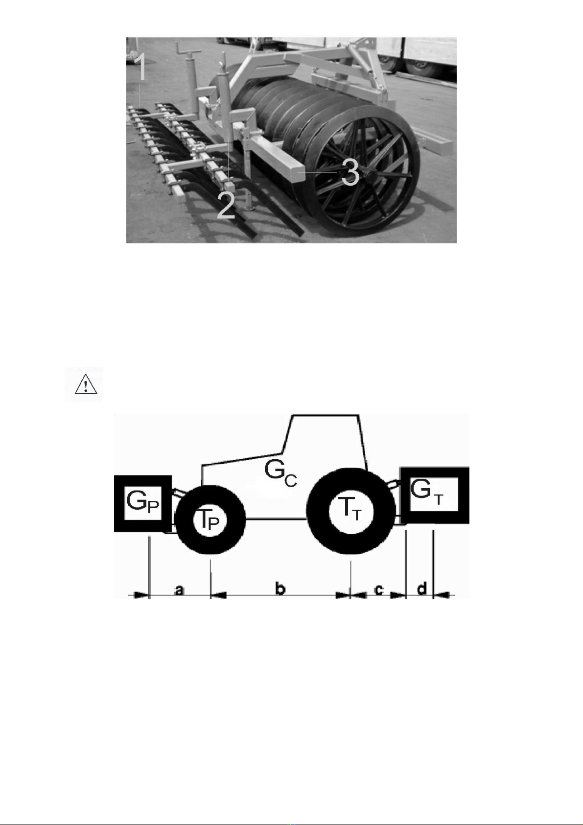
•Make sure that the tractor with the attached unit is stable, and the tractor steerability
and stopping power can be maintained. The load on the front axle cannot decrease to
less than 20% of the total load on the tractor axle –use a set of front-mounted
weights.
•When in resting position and disconnected from the tractor, the machine must be
stable all the time.
•The supporting foot must rest on a stable ground. It is forbidden to use any pads
under the foot as it may result in support instability.
3.2. Hydraulic system
The hydraulic system operates under high pressure. Apply all precautionary
measures, in particular:
•do not connect and disconnect hydraulic hoses when the tractor hydraulic system is
pressurised (hydraulics set to neutral),
•check regularly the conditions of connections and hydraulic hoses,
•while repairing a hydraulic or pneumatic malfunction, withdraw the machine from
service.
3.3. Transport on public roads
For the period of transport, the side sections of the roller MWC/MWW must be put in
transport position using the hydraulic system. Before folding, the machine must be lifted
sufficiently high until the folded side sections do not collide with the ground.
The roller must be protected against unfolding by means of the mechanical lock.
While in transport, the clearance under the machine must be at least 30 cm.
While transporting the unit on public roads, it is absolutely mandatory to use lights, an
identification sign and reflective side lights in case it is attached to the rear three-point

10
linkage. The rolled attached to the front three-point linkage should feature side-marker and
reflective lights. If the tractor’s headlights are not visible, their equivalents should be
installed on the machine.
While transporting, do not exceed the speed, which is:
–up to 20 km/h on smooth-surface (asphalt) roads,
–6-10 km/h on field or sett paving roads,
–up to 5 km/h on bumpy roads.
Travelling speed must be adapted to the road and the existing conditions so that the roller
cannot jump on the tractor suspension system and excessive loads on the machine frame
and the tractor suspension system can be avoided.
Act with due caution when passing and overtaking or travelling at curves. The permissible
width of the machine travelling on public roads is 3.0 m.
WARNING! Any failure to observe the above rules may pose hazard to the
operator and other people. It may result in damaging the machine as well.
The user shall be liable for any damage caused by the failure to observe
the rules!
3.4. Description of residual risk
Mandam Sp. z o. o. act with due diligence to eliminate the risk of accidents. However,
there is some residual risk that may result in an accident. The greatest risk is posed:
•if the machine is not used according to this manual,
•if the machine is operated by persons under age, disabled or intoxicated (under the
influence of alcohol or drugs),
•if persons or animals are present within reach of the machine,
•if caution is not paid during transport and maneuvering with the tractor,
•if persons are standing on the machine or between the machine and the tractor when
the engine is running,
•during operation when operation guidelines are not followed,
•when travelling on public roads.
3.5. Residual risk assessment
Residual risk may be reduced to a minimum provided the following recommendations
are applied:
•operate the machine carefully and without rush,
•read the manual carefully,
•keep clear from hazardous zones,
•it is forbidden to stand on the machine or be present in the working zone when the
engine is running,
•perform maintenance in accordance with safety rules,
•wear safety clothes and a safety helmet while working under the machine,
•prevent unauthorised persons from accessing the machine, in particular children.

11
4. General operation instructions
The Campbell roller with its hitch at the front comprises three main elements:
–Main frame of the roller
–Working roller
–Smoothing harrow (optional)
The main frame is a load-bearing element of the entire structure and the working
roller. The frame is composed of two elements: a three-point universal hitch (so-called front
drawbar) and a load-bearing frame of the roller. It is made of hollow sections. The working
roller is attached to the frame. The frame of the roller is equipped with two supporting feet
that secure it from accidental tilt.
The roller drawbar is a structure component used to attach the roller to the tractor.
The special design of the hitch allows for attaching the roller to the front three-point linkage
of the tractor. The front drawbar is equipped with two rollers that make it possible to change
the drawbar position with regard to the frame during the operation on the front three-point
linkage of the tractor.
The working roller is an element comprising several iron casts located on the
working roller axle equipped with bearings on two self-adjustable bearing units. The
bearings are contamination and misalignment resistant, thanks to which the operation is
trouble-free. Chains are pulled between the wheels to protect against soil sticking to the
roller.
The smoothing harrow is a set of two rows of teeth working in front of the roller that
crush and even the soil. It is mounted to the frame with a crank that is also used for its
adjustment.
4.1. Before using the roller
The roller is usually supplied for sale in a ready-to-operate condition on the front three-
point linkage. Due to transport limitations, the roller may be delivered with a disassembled
harrow. Before commencing the work, the roller should be mounted on the frame on the
opposite side of the tractor suspension system (Fig. 2).

12
Fig. 2 Location of the smoothing harrow on the MWW roller: 1 - smoothing harrow, 2 - depth
adjustment crank, 3 - frame
Tyre pressure in the tractor wheels must comply with the values recommended by the
manufacturer. The lower bars of the three-point linkage should be at the same height,
spaced correspondingly to the spacing of the lower points of suspension. While attaching
the roller to the tractor, the roller must be placed on hard and even ground.
CAUTION! Do not exceed the permissible axle load and tyre carrying
ability. The front axle load cannot be lower than 20 %.
Fig. 3 Diagram of the markings of tractor loads.
Axle load calculations
Marking:
GC–tractor weight,
TP–front axle load if the tractor is empty,
TT–rear axle load if the tractor is empty,
GP–total weight of the rear-mounted machine,
GT–total weight of the front-mounted machine,
a –distance between the centre of gravity of the front-mounted equipment and the axle

13
centre,
b –tractor wheelbase,
c –distance between the rear axle centre and the centre point of the hitch bolt of the rear-
mounted equipment,
d –distance between the machine centre of gravity from the hitch bolts (roller without
smoothing harrow –0.8 m, roller with smoothing harrow),
x –distance of the centre of gravity from the rear axle (assume 0.45 if the manufacturer
does not provide this parameter).
Minimum load at the front if this is a rear-mounted machine:
Minimum load at the back if this is a front-mounted machine:
Actual load on the front axle:
Actual total weight:
Actual load on the rear axle:
While attaching the smoothing harrow to the three-point linkage of the tractor, complete
the following steps:
•Switch the tractor hydraulic system into adjustment position.
•Remove lower hitch bolts (if the tractor lift is not equipped with hooks).
•Drive forwards carefully, suspend the machine on the lower bars and secure.
•attach the tractor upper fastener; during operation of the unit, the hitch point of the
upper fastener at the unit must be higher than the attachment point of this fastener at
the tractor.
•Check the operation of roller lifting, lowering and the hydraulic system.
CAUTION! Before using the roller, check all bolted joints and retighten them
if necessary.

14
CAUTION! Before folding and unfolding of the side wings, pull the string to
release the roller locks
4.2. Adjustments
The roller operates by gravity and requires no adjustments of its operation. The
smoothing harrow can be optionally adjusted in terms of working depth. For this purpose,
the crank mounted on the harrow arm in front of the roller in working position is used (Fig.
1).
4.3. Operating the roller
Start working with the roller by making the first trial passage. During this task, check
roller adjustment and manner of operation. If necessary, adjust the length of the tractor
fastener so that the roller frame is position horizontally. Travelling speed while working with
the roller should be up to 10 km/h.
CAUTION! Act with due caution while attaching the roller to the tractor and
maintain the minimum speed of the tractor.
A properly attached and adjusted roller should travel behind or in front of the tractor
along a straight line and compact soil at the entire working width.
CAUTION! Do not operate the roller soil which is too wet because the roller
will be covered with soil.
CAUTION! Do not operate the roller on rocky soil because the working
elements on the roller may become cracked.
4.4. Troubleshooting
Due to its simple design and the applied materials, the roller encounters malfunctions
at an exceptionally low rate. Due to the application of GG20 cast iron of higher strength for
rim casts, rim durability is improved. Remember that following all guidelines presented in
this manual with regard to operation, adjustment, lubrication, transport and storage
considerably contributes to longer trouble-free lifetime.
4.5. Roller maintenance
•After completing the work, lubricate roller bearings, hinges and cylinder bolts (at least
every 25 hours of operation).For lubrication purposes, the grease of type ŁT-43 can
be used.
•Once the work is completed, the soil residues must be removed from the roller.

15
Inspect connection and sub-assemblies as well. Retighten loose screwed joints.
Replace or refurbish any damaged or worn parts.
•Working elements of the smoothing harrow can be used until they are almost entirely
worn or their performance is inefficient.
•Use only genuine screws and nuts when replacing worn parts.
•Always remember to tighten the screwed joints properly.
•Replace or refurbish any damaged or worn parts.
•Before a new work season is commenced, always add up the grease in the bearing
units.
CAUTION! During any maintenance work, the roller must rest on the
ground. The tractor engine must be stopped.
Hydraulic system maintenance
Maintenance of the hydraulic system (Fig.4) consists in visual inspections to prove
leak tightness. Remember to insert pins into quick-fit connectors. If there is an oil leakage
from connections of hydraulic hoses, the connector must be tightened. If the oil leakage is
not remedied, replace the element or the hose with a new one. If the leakage occurs
outside the connector, the leaking hose must be replaced with a new one. Mechanical
damage also requires replacement of the sub-unit. It is recommended that the hydraulic
hoses should be replaced every 5 years.
If oil appears on the piston rod of the hydraulic cylinder, check for the nature of the
leakage. Check the sealing once the piston rod is fully moved out. Small leakage which
results in covering the piston rod with an oil film is acceptable (damaged wiper seal). If the
amount of oil is greater or there are oil drops, shut down the unit for the period required to
repair the malfunction (damaged sealing).

16
Fig. 4 Diagram of the hydraulic system of the MWC/MWW roller: 1- cylinder, 2- quick-
connector, 3-T-connector, 4- flange, 5- copper washer, 6- hydraulic line 1.2 m, 7- hydraulic
line1.0 m, 8- hydraulic line 2.2 m
5. Storage of the roller
When the work season is finished, the parts and the sub-units have to be inspected. If
any part is found damaged or considerably worn, replace it with a new one. Areas of
damaged paint must be cleaned out of dirt and rust. Apply anti-corrosive paint, and then
apply a topcoat paint. Provide corrosive protection on the working surfaces of the roller. If
possible, store the roller under a roof, protected against any access of unauthorised
persons and animals.
CAUTION! While in storage, the roller frame must be resting on the support
feet. The roller should be set only on hardened surface with a slope up to
8.5°. Put wedges under the roller.

17
6. Transporting the roller
For transporting the roller, a three-point linkage on the tractor (front or rear-mounted)
is used.
CAUTION! Travelling on public road with a roller the length and height of
which is over 3.0 m and 4.0 m respectively is forbidden due to its excessive
travel width.
CAUTION! While transporting the roller attached to the rear-mounted three-
point linkage, only tractors equipped with a set of front axle weights are
allowed. In case of the front axle, place the additional load on the rear axle
as required.
If the roller is transported on the rear-mounted three-point linkage, before entering any
public road, place an identification emblem for slow-driving vehicles in the roller holder and
position holders of reflective lights so that white reflective elements face the travelling
direction of the tractor. The rolled attached to the front three-point linkage should feature
side-marker and reflective lights. If the tractor’s headlights are not visible, their equivalents
should be installed on the machine. While being transported, the roller must be positioned
sufficiently high to ensure that the clearance beneath the roller is at least 30 cm.
Fig. 5 Position of the MWC/MWW roller during transportation.

18
Table 3 Transportation dimensions of the MWC/MWW rollers
Type
Wheel diameter [mm]
H [m]
B [m]
MWC/MWW 1.5
700
1.2
1.65
800
1.25
1.65
900
1.3
1.65
MWC/MWW 2.5
700
1.2
2.6
800
1.25
2.6
900
1.3
2.6
MWC/MWW 3.0
700
1.2
3.0
800
1.25
3.0
900
1.3
3.0
MWC/MWW 4.0 H
700
1.9
2.6
800
1.95
2.7
900
2.0
2.8
MWC/MWW 6.0 H
700
2.7
2.8
800
2.75
2.9
900
2.8
3.0
While travelling, tractor must be driven as close to the right side of the road as
possible. Act with due caution when overtaking or passing other participants of road traffic.
CAUTION Travelling on public roads without warning marks and lights
required by law may result in an accident!
7. Disassembly and withdrawal from service
If the degree of damage of the machine frame may pose hazard to life or cause an
accident, withdraw the machine from service. The disassembled and withdrawn from use
roller does not pose any particular threat to the natural environment. The roller consists of
elements made of steel and cast iron. Start disassembling the roller by dismounting small
parts (bolts, rings, etc.). Then, proceed with bigger parts.
Next, separate cast iron elements of wheel rims from other steel elements. Once
disassembled, the roller must be handed over to scrap metal yard, which accepts steel and
cast iron, for recycling. Wires and used oil should be disposed of at a waste management
company.

19
8. Technical description
Table 3 Technical data of the MWC roller
Type
Working
width [m]
Number of
wheels
[pcs]
Wheel
diameter
[mm]
Wheel
edge angle
[º]
Min. power
demand [HP]
Weight
[kg]
MWC 1.5
1.5
8
700
30
60
750
8
800
60
850
8
900
60
1000
MWC 2.5
2.5
13
700
30
60
817
13
800
70
1200
13
900
70
1350
MWC 3.0
3.0
15
700
30
60
935
15
800
70
1182
15
900
70
1450
MWC 4.0H
4.0
24
700
30
80
1390
24
800
90
1800
21
900
85
2562
MWC 6.0H
6.0
36
700
30
120
2210
36
800
130
2780
31
900
140
3220

20
Table 4 Technical data of the MWW roller
Type
Working
width [m]
Number of
wheels
[pcs]
Wheel
diameter
[mm]
Wheel
edge
angle [º]
Number
of teeth
[pcs]
Min. power
demand [HP]
Weight
[kg]
MWC 1.5
1.5
8
700
30
13
60
862
8
800
60
962
8
900
60
1112
MWC 2.5
2.5
13
700
30
21
60
947
13
800
70
1330
13
900
70
1480
MWC 3.0
3.0
15
700
30
25
60
1075
15
800
70
1360
15
900
70
1590
MWC
4.0H
4.0
24
700
30
33
80
1630
24
800
90
2040
21
900
85
2802
MWC
6.0H
6.0
36
700
30
51
120
2540
36
800
130
3110
31
900
140
3550
This manual suits for next models
6
Table of contents
Other Mandam Farm Equipment manuals

Mandam
Mandam BTH-D User manual

Mandam
Mandam ORKAN VARIO Series User manual

Mandam
Mandam MGX 2200 User manual

Mandam
Mandam GAL-C User manual

Mandam
Mandam MCH Series User manual

Mandam
Mandam Hybro 3,0 User manual

Mandam
Mandam SUPER User manual

Mandam
Mandam MBS User manual

Mandam
Mandam ORKAN 3+ User manual

Mandam
Mandam SAL DISC HARROW User manual