Mandam RHINO User manual

MANDAM Sp. z o.o.
ul. Toruńska 14 44-100 Gliwice, Poland
e-mail: [email protected]
Tel.: 032 232 26 60 Fax: 032 232 58 85
NIP (VAT no.): 648 000 16 74 REGON (Registration no.): P – 008173131
INSTRUCTION MANUAL
RHINO CHISEL CULTIVATOR
Issue II
Gliwice 2022

2
DECLARATION OF CONFORMITY
FOR A MACHINE
In accordance with the Ordinance of the Minister of the Economy dated 21 October 2008 (Journal of Laws No. 199, item
1228)
and the Directive of the European Union no. 2006/42/EC of 17 May 2006
MANDAM Sp. z o.o.
ul. Toruńska 14
44-100 Gliwice
hereby declares at its sole responsibility that the following machine:
under this declaration, complies with:
the Ordinance of the Ministry of Economy of 21 October 2008 on fundamental
requirements for machinery (Journal of Laws No. 199, item 1228)
and the Directive of the European Union 2006/42/EC of 17 May 2006.
The persons responsible for the technical documentation for the machine: Jarosław Kudlek,
Łukasz Jakus
ul. Toruńska 14, 44-100 Gliwice, Poland
For assessment of compliance the following standards have been applied:
PN-EN ISO 13857:2010
PN-EN ISO 4254-1:2016-02
PN-EN ISO 12100-1:2005/A1:2012
PN-EN ISO 12100-2:2005/A1:2012
PN-EN 982+A1:2008
This EC Declaration of Conformity shall be cancelled
if the machine is modified or redesigned without consent of the manufacturer.
…………………………………………….
………………………………………
Place and date of issue
First and last name, position held
and signature of the person authorized
RHINO CULTIVATOR
type/model:…………………………………
serial number:………………………………
year of manufacture:………………………..

3
1. Introduction .................................................................................................................................4
1.1. Safety symbols and inscriptions ...........................................................................................5
2. General information....................................................................................................................7
2.1. Design of the RHINO chisel cultivator................................................................................7
2.2. RHINO chisel cultivator – intended use..............................................................................8
3. General safety information.........................................................................................................8
3.1. Proper hitching and unhitching from the tractor ...............................................................9
3.2. Tyres......................................................................................................................................9
3.3. Hydraulic system ..................................................................................................................9
3.4. Transport safety on public roads........................................................................................10
3.5. Residual risk description ....................................................................................................10
3.6. Residual risk assessment ....................................................................................................10
4. General information on the use of the implement..................................................................11
4.1. Before using the cultivator.................................................................................................12
4.1.1. Installation of the drawbar .............................................................................................................. 12
4.1.2. Installation of drawbar lights .......................................................................................................... 13
4.1.3. Installation of rear assemblies ......................................................................................................... 13
4.2. Hitching the cultivator with the tractor .............................................................................17
4.3. Operation and adjustment..................................................................................................17
4.3.1. Hydraulic lock of side extensions .................................................................................................... 17
4.3.2. Implement opening sequence........................................................................................................... 18
4.3.3. Beam position adjustment................................................................................................................ 20
4.3.4. Roller position adjustment............................................................................................................... 22
4.3.5. Levelling disc position adjustment.................................................................................................. 24
4.4. Rules for transporting the cultivator on public roads and lighting the implement .........25
4.5. Maintenance and lubrication.............................................................................................26
4.6. Screw tightening torque .....................................................................................................27
5. RHINO cultivator maintenance ...............................................................................................28
5.1. Maintenance of the RHINO driving system......................................................................29
5.2. Defects and malfunctions in the cultivator operation.......................................................30
6. Cultivator storage......................................................................................................................31
7. Disassembly and withdrawal from service and scrapping ....................................................32
8. RHINO cultivator – spare parts...............................................................................................32

4
1. Introduction
Congratulations on your purchase of the RHINO cultivator.
This instruction manual provides information on the hazards that may occur during use,
cultivator operation, technical data and the most important indications and
recommendations, the knowledge and use of which is a prerequisite for proper operation.
Keep this manual for future reference. Should you have any problems with understanding
any statement in the instruction manual, please contact the manufacturer.
The following mark indicates the guidelines that are important due to safety reasons:
Machine identification
Identification data of the RHINO cultivator, including basic information on the
manufacturer and the machine and CE marking, can be found on the rating plate placed
on the main frame.
The warranty for the cultivator is valid for 12 months from the date of sale.
The warranty card constitutes an integral part of the machine.
Whenever you request any information on spare parts, provide the serial number.
For more information on spare parts,
•please visit our website at: http://mandam.com.pl/parts/
•call us at +48 668 662 289
•e-mail us at: [email protected]
5
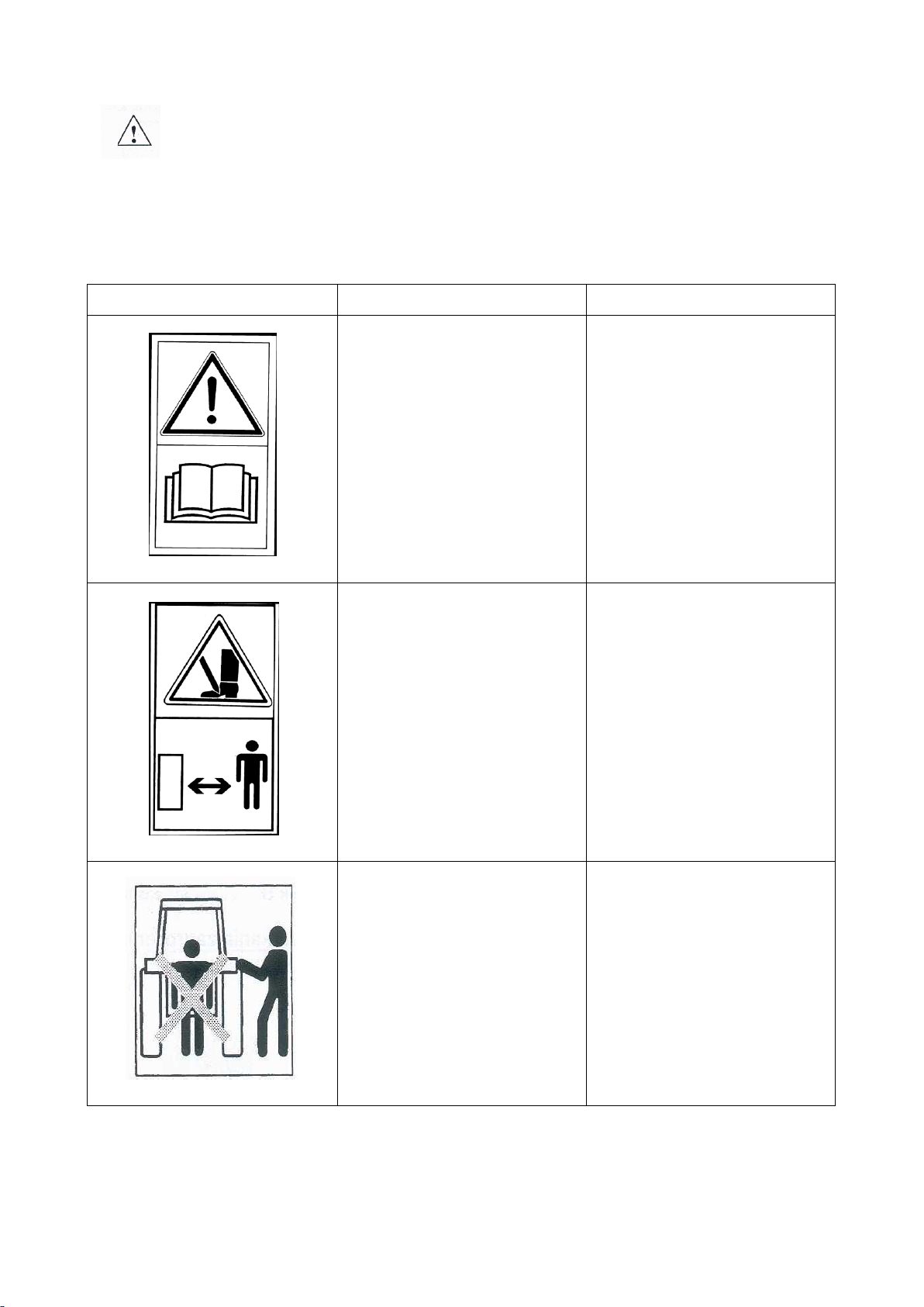
1.1. Safety symbols and inscriptions
Remember! Special care must be taken when using the cultivator in case of
areas marked with special information and warning signs (yellow stickers).
The following symbols and inscriptions can be found on the implement. Secure the
symbols, signs and inscriptions against loss and make sure they are legible at all times. If
lost or illegible, replace the signs and inscriptions with new ones.
Table 1. Information and warning signs
Safety sign
Meaning of the safety sign
Location on the implement
Read the instruction manual
prior to operating the
implement.
Frame adjacent to the
mounting place of the upper
fastener
Danger of toe or foot crush
Frame adjacent to the
mounting place of the upper
fastener
Keep clear from lift bars
while controlling the lift
Frame adjacent to the
mounting place of the upper
fastener
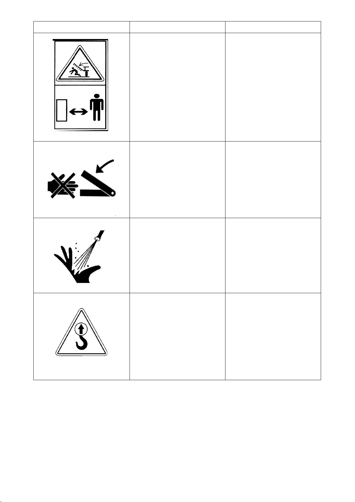
6
Safety sign
Meaning of the safety sign
Location on the implement
Keep clear from foldable
and moving parts of the
implement
Front part of the central
frame adjacent to side
frames
Do not reach into the
crushing zone if the
elements can move
Central frame adjacent to
side frames
Pressurized fluid – hazard of
bodily injury
Cylinders
Fixing point for transport
belts
Upper part of the drawbar
(upper fastener bolt)
Rear part of the frame
(adjacent to the cylinder
bolt on the cetral frame)
7
2. General information
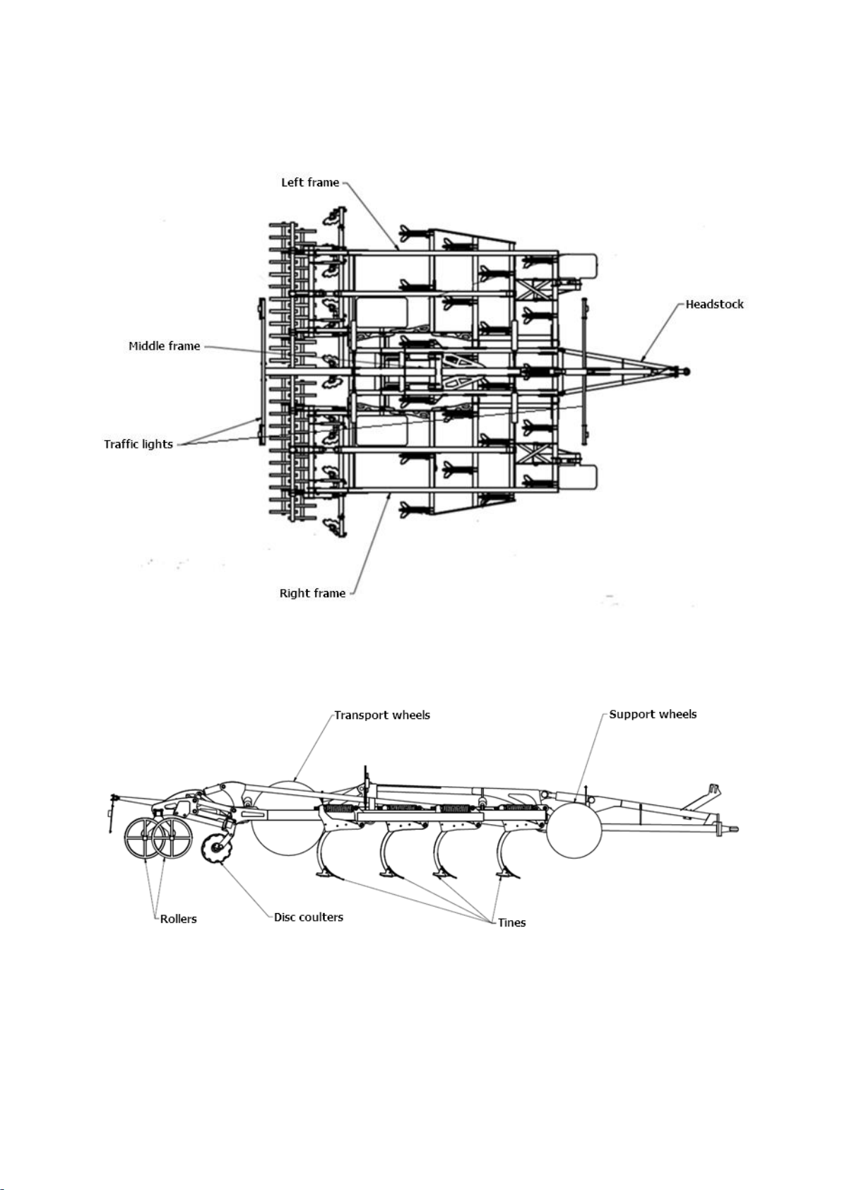
2.1. Design of the RHINO chisel cultivator
Fig. 1 RHINO 6.0 H chisel cultivator (top view).
Fig. 2 RHINO 6.0 H chisel cultivator (side view).

8
Table 2. RHINO cultivator specifications
Type
Working width
[m]
Number of
tines [pcs]
Number of
discs [pcs]
Weight [kg]
RHINO 4.0 H
4.00
15
10
5840
RHINO 6.0 H
6.00
21
12
6352
The cultivator consists of a central frame and side frames which can be folded
hydraulically into the transport position (Fig. 1). Beams with workpieces are attached to
the frame. As a standard, the cultivators are equipped with C-Ring tandem rollers and a
disc beam. Each disc has its own bearing arrangement (maintenance-free hubs), which
allows for an optimum inclination of the disc in relation to the direction of travel and the
ground. The purpose of the discs is to level out the soil surface deformed by the last row
of workpieces. The rollers are used to compact the aerated soil and maintain the working
depth of the cultivator.
2.2. RHINO chisel cultivator – intended use
The RHINO chisel cultivator is a universal agricultural stubble cultivation and tillage
machine designed for:
•shallow stubble cultivation (up to 15 cm) to mix post-harvest crop residues, stop
soil evaporation, accelerate weed and self-sown plant growth and reduce
ploughing resistance or deep cultivation,
•deep cultivation (up to 35 cm) to aerate the soil tillage layer, mix mineral and
organic fertilisers and prevent the mineralisation of humus in the arable layer.
The use of right- and left-side mouldboards increases the stubble mixing intensity,
which results in a decrease in the intensity of phenolic compounds that negatively affect
the grain development in the following year. The use of RHINO cultivator for deep
cultivation excludes the need for ploughing, which reduces costs, decreases the risk of
over-compaction of soil and increases the possibility of timely completion of activities.
CAUTION! The cultivator is designed for agricultural use only. Using the
implement for tasks that differ from the intended use shall be regarded as
misuse, resulting in loss of warranty. Failure to follow the guidelines included
in this instruction manual shall be regarded as misuse.
CAUTION! The manufacturer shall not be liable for any damage arising out of
misuse.
3. General safety information
The cultivator can be operated and repaired only by persons familiar with its
operation and the attached tractor as well as the rules of safe operation and maintenance
of the tillage cultivator. The manufacturer shall not be liable for any unauthorised
alternation of the cultivator. Only genuine MANDAM spare parts shall be used during the
warranty period.
The cultivator must be operated with all precautionary measures, in particular:
•each time before starting operation check the cultivator and the tractor whether
their condition guarantees safety during operation and travel,
•minors, disabled or intoxicated persons (under the influence of alcohol or drugs)

9
must not operate the machine,
•wear work clothes, shoes and gloves during maintenance,
•do not exceed the maximum axle loads and transport dimensions,
•use only original cotter pins and pins,
•while using the cultivator, no bystanders, in particular children can be present in
the vicinity when the machine is being lowered, lifted, unfolded or dismounted,
•do not stay between the tractor and the cultivator when the engine is running,
•move forward, lift and lower the cultivator slowly and smoothly without sudden
jerks, making sure that nobody stays in the vicinity,
•during the operation and travel do not stand on the implement and do not put
additional loads onto it;
•while making U-turns, pay due caution if anyone is in the vicinity,
•any repairs, lubrication or cleaning of working components may be performed as
long as the engine is not running and the implement is lowered and unfolded,
•while taking a break, lower the implement onto the ground and stop the tractor
engine, store the implement properly so that no person or animal can be injured,
•no U-turns or reversing is allowed with the lowered implement.
3.1. Proper hitching and unhitching from the tractor
•Make sure that the cultivator is hitched to the tractor in accordance with the
instructions, remembering to secure the bolts and that the bolts are secured with
cotter pins.
•While hitching the tractor with the cultivator, do not stay between the implement
and the tractor;
•The tractor used together with the cultivator must be fully functional and in good
working order. Do not attach the implement to a tractor with a defective hydraulic
system.
•Remember to observe the following: balance of the tractor and the suspended
implement, tractor steerability and braking performance – the front axle load must
not drop below 20% of the total tractor load – a kit of front weights;
•When in resting position and disconnected from the tractor, the machine must be
stable all the time.
•Place the support leg on a stable ground. Do not use pads under the leg as this may
cause instability.
3.2. Tyres
•Tyre pressure cannot exceed the value recommended by the manufacturer.
Transporting the implement when the pressure is too low is prohibited. This may
cause damage to the implement or an accident when travelling too fast and on very
uneven surfaces.
•Considerably damaged tyres (particularly the tyre profile) must be replaced
immediately.
•Protect the implement from rolling away when replacing the tyres.
•The repair works on wheels or tyres must be performed by persons trained and
authorised for this purpose. Such works must be performed with properly selected
tools.
Following every assembly of wheels, check the tightening of nuts after travelling the
distance of 50 km.
3.3. Hydraulic system
The hydraulic system operates under high pressure. Take all precautionary

10
measures, in particular:
•do not connect and disconnect hydraulic hoses when the tractor hydraulic system is
pressurised (hydraulics set to neutral),
•check regularly the conditions of connections and hydraulic hoses,
•do not use the implement until the hydraulic system is repaired.
3.4. Transport safety on public roads
Before driving on public roads, fold the side sections of the RHINO cultivator to the
travel position using the hydraulic system. Before folding, the machine must be lifted
sufficiently high until the folded side sections do not collide with the ground.
Use the hydraulic lock to secure the cultivator against unfolding.
While in transport, the clearance under the machine must be at least 30 cm.
When driving on public roads, it is absolutely mandatory to use lights, a marking plate and
side retroreflectors in case the implement is attached to the rear three-point hitch.
Do not exceed the maximum travel speeds:
–up to 20 km/h on smooth (asphalt) roads,
–6-10 km/h on dirt roads or cobblestones,
–up to 5 km/h on bumpy roads.
Adapt the drive speed to the road conditions to prevent the cultivator jumping on the
three-point hitch and to prevent excessive loads on the implement frame and the three-
point hitch.
Act with due caution when passing and overtaking or travelling at curves. The maximum
implement width on public roads is 3.0 m.
WARNING! Any failure to observe the above rules may pose hazard to the
operator and other people. It may also result in damaging the machine. The
user shall be liable for any damage caused by failure to observe the rules!
3.5. Residual risk description
Mandam Sp. z o.o. makes every effort to eliminate the risk of accidents. However,
there is some residual risk that may result in an accident. The biggest hazard occurs
when/during:
•using the implement for purposes other than described in the manual,
•operating the implement by people who are underage and do not have licences,
are ill or intoxicated,
•presence of people and animals within the implement operating range,
•precautionary measures are not taken during transport and maneouvering with the
tractor,
•staying on the implement or between the tractor and the implement when the
engine is running;
•during operation when operation guidelines are not followed,
•driving on public roads.
3.6. Residual risk assessment
The residual risk can be minimised by applying the following recommendations:
•operate the implement carefully and without undue haste,
•read the instruction manual carefully,
•keep a safe distance from hazard zones,
•do not stay on the implement and within the implement operating range when the
engine is running,
•perform the maintenance in accordance with safety rules,
11
•wear safety clothes and a safety helmet while working under the implement;
•prevent the access of unauthorized personnel and especially children to the
implement.
Hazards:
Noise: If the RHINO cultivator is used on stony soils, it can generate a lot of noise. In this
case, it is advisable to close the tractor windows and doors. One can also wear hearing
protection.
Dust: In very dry conditions, very heavy dusting can occur. In such cases, it is
recommended that the doors and windows of the tractor remain closed. The use of a dust
mask is recommended under extreme conditions.
4. General information on the use of the implement
Before the machine is put into operation for the first time:
•read the instruction manual,
•make sure that the machine is in proper operating condition,
•check the condition of the hydraulic system (replace damaged components, e.g.
pressure hoses),
•make sure that the hydraulic hose quick-connectors of the machine match the
tractor sockets,
•check the tightening of bolts and nuts,
•check if the air pressure in tyres is according to the manufacturer’s
recommendations,
•make sure that all components requiring lubrication are lubricated,
•make sure the tyre pressure in the tractor wheels is equal on both axes to ensure
even operation.
CAUTION! The permissible loads on the axles and tyre load capacities must
not be exceeded. The front axle load must not be less than 20% of the total
load. Tyre pressure must comply with the values recommended by the
manufacturer.

12
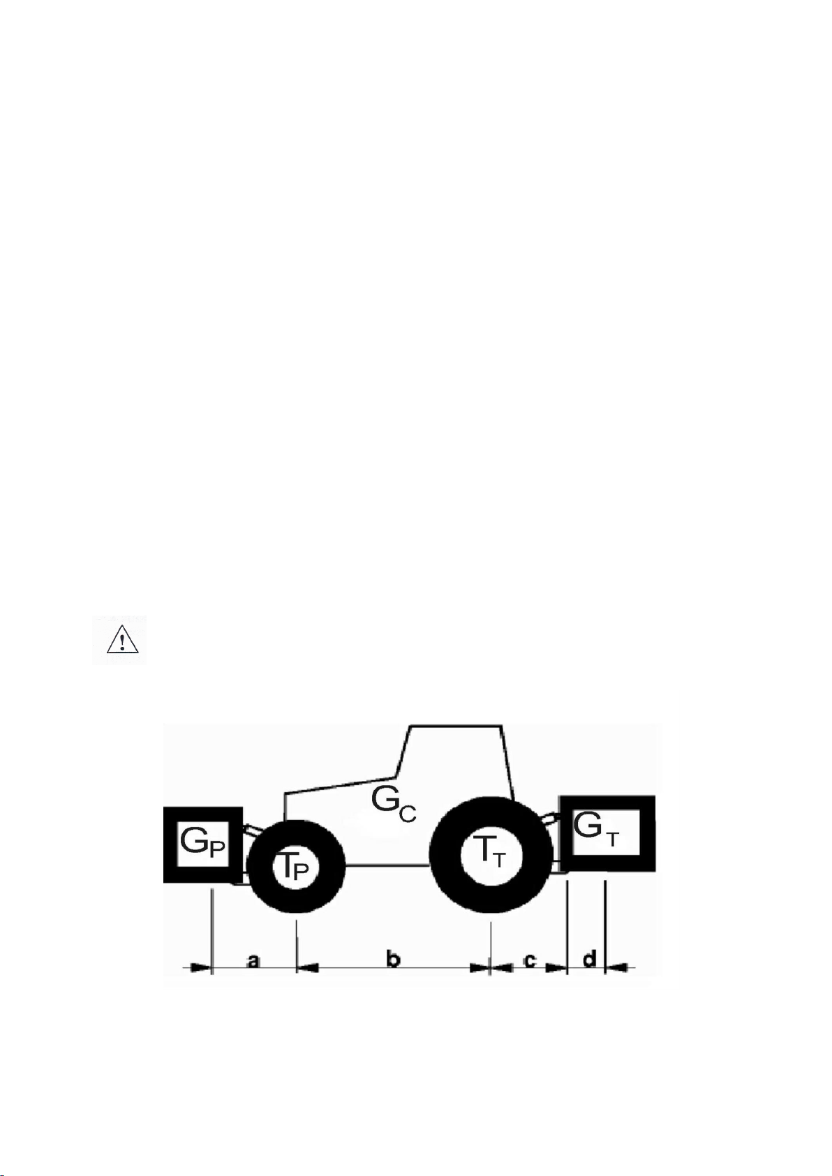
Axle load calculations
Key:
GC – tractor weight,
TP – front axle load for the unhitched tractor,
TT – rear axle load for the unhitched tractor,
GT – total weight of the equipment attached at the back,
GP – total weight of the front-mounted machine,
a – distance between the centre of gravity of the front-mounted equipment and the axle
centre,
b – tractor wheelbase,
c – distance between the rear axle centre and the centre point of the hitching pin of the
rear-mounted implement,
d – distance of the centre of gravity of the agricultural implement from the hitching pins
of the tractor,
x – distance of the centre of gravity from the rear axle (assume 0.45 if the manufacturer
does not provide this parameter).
Minimum load at the front in case of a rear-mounted implement:
Actual load on the front axle:
Actual total weight:
Actual load on the rear axle:
4.1. Before using the cultivator
The cultivator is usually supplied for sale in a ready-to-operate condition. Due to the
limitations of the means of transport, it is also possible to deliver it in a partially
disassembled condition – usually by disconnecting the roller assembly, beams with discs,
drawbar and lights.
When preparing the unit for operation for the first time, its components must be
assembled such as the cultivator, the roller, the discs and the drawbar. To this end, place
the cultivator on a flat hard surface and start assembling the components.
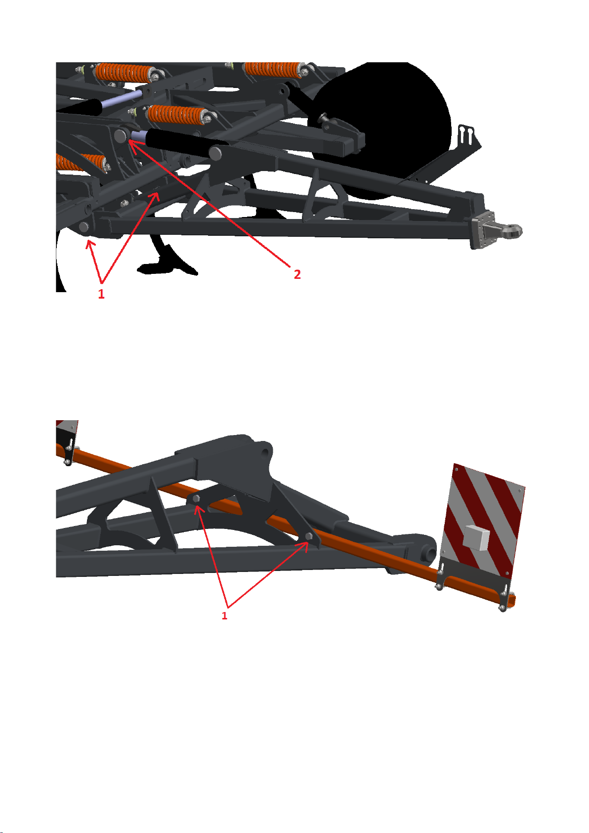
4.1.1. Installation of the drawbar
To mount the drawbar to the main frame of the cultivator, first set the lower
fasteners (Fig. 3 – No. 1) so that the holes coincide with the mounting holes in the frame.
They must then be secured with Ø50 pins, washers and expansion sleeves. Next, tilt the
drawbar so that the actuator mounting hole coincides with the mounting hole in the frame
(Fig. 3 – No. 2) and secure the connection with the Ø50 pin, washer and expansion sleeve.
13
Fig. 3 Installation of the drawbar.
4.1.2. Installation of drawbar lights
To mount the beam with lights on the drawbar, position it so that the mounting holes
on the beam and on the drawbar coincide (Fig. 4 – No. 1) and then tighten with M20 bolts
and self-locking nuts.
Fig. 4 Installation of drawbar lights.
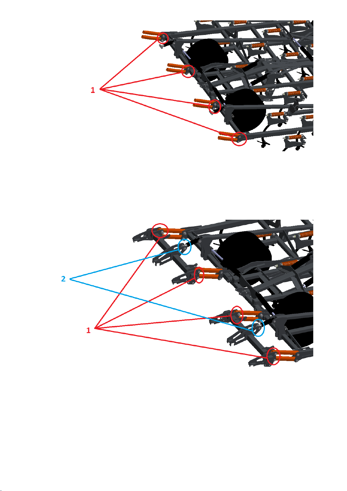
4.1.3. Installation of rear assemblies
The installation of the roller assembly should be started with the attachment of the
arms (8 pieces); the fixing points to the frame are shown in Fig. 5 – No. 1. The mounting
holes in the frame and in the arms should be secured by means of Ø40 pins, castle nuts
and pins.
14
Fig. 5 Arm installation on the drawbar.
Then you can proceed with the assembly of the rear mounting assembly. Start with
the attachment to the arms (Fig. 6 – No. 1). When the assembly mounting holes and arm
holes overlap, force the Ø40 pin must and secure the elements with castle nuts and pins.
Next, attach the actuators to the assemblies in the places shown in Fig. 6 – No. 2.
Use Ø36 pins, washers and expansion sleeves for this purpose.
Fig. 6 Installation of the rear mounting assembly.
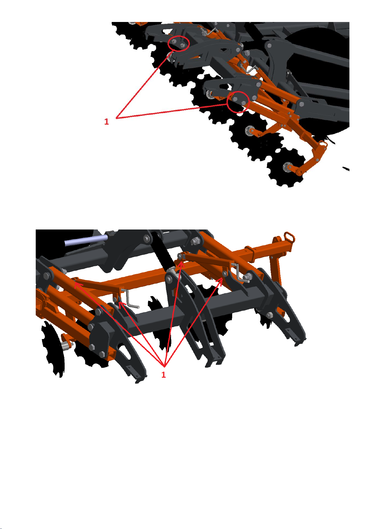
After installing the rear mounting assembly, proceed with the installation of the
disc beam assembly or the roller assembly. The disc beams are mounted on arms which
are bolted to the mounting assembly using M30 bolts and nuts with washers. The fixing
points are shown in Fig. 7 – No. 1.
15
Fig. 7 Installation of disc beams.
After screwing in the disc beams, remember to install adjusting cranks. Their fixing
points are shown in Fig. 8 – No. 1.
Fig. 8 Fixing point of the disc beam adjusting cranks (No. 1).
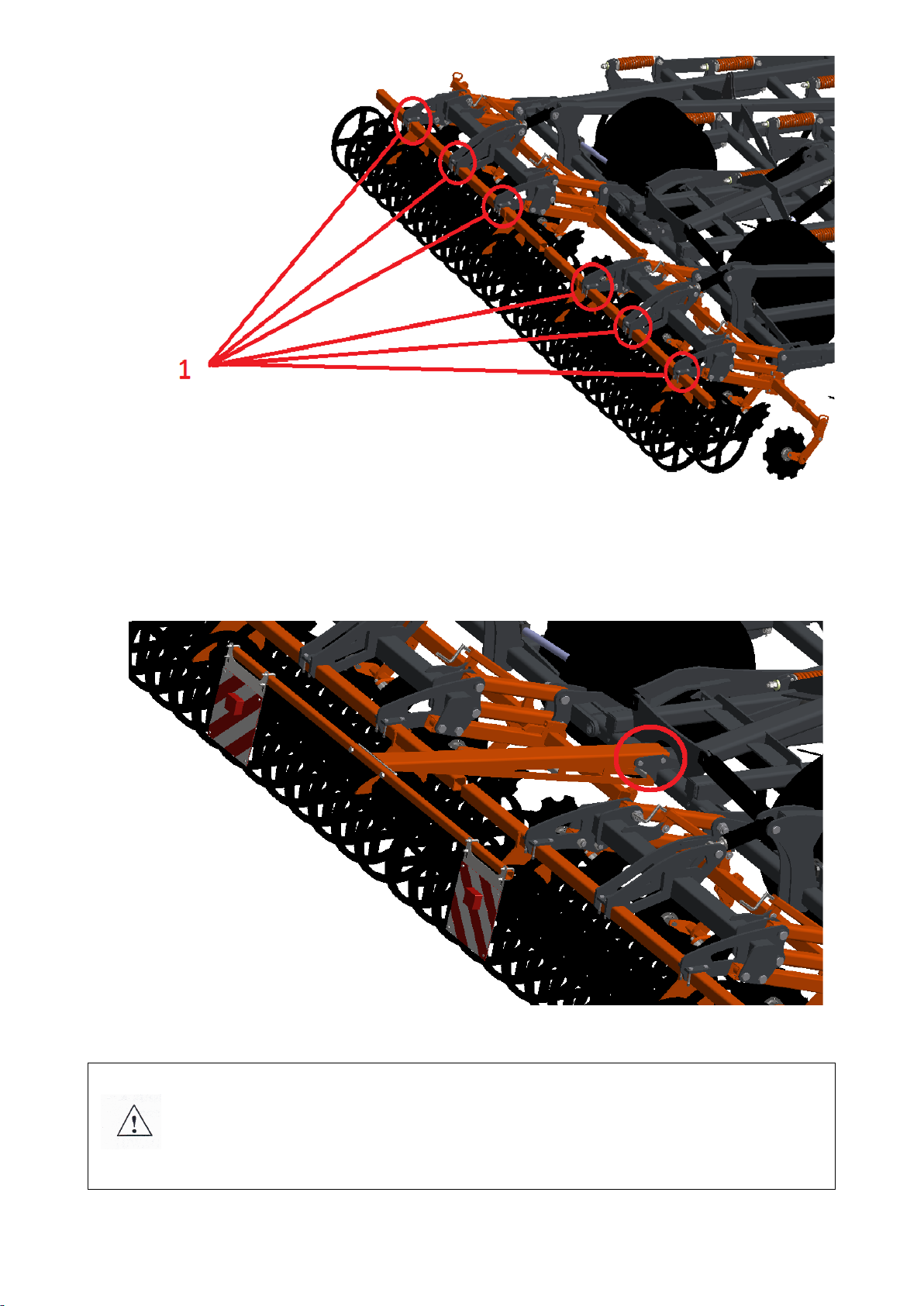
Next, bolt the roller assemblies to the mounting assembly. Use flat bars with
through-holes, M16 screws and nuts. The figure below shows the locations of the fixing
points.
16
Fig. 9 Fixing points of the roller assembly (No. 1).
Finally, mount the beam with lights. They are attached with two M20 bolts,
together with washers and nuts.
Fig. 10 Light fixing point.
CAUTION! The correct procedure for mounting the rollers in the arm clamps
requires that the screws are tightened evenly diagonally so that the entire
plane of the arm brackets is flush with the plane of the roller clamp profile.
This provides the most secure way of connecting the roller arms to the
machine!
17
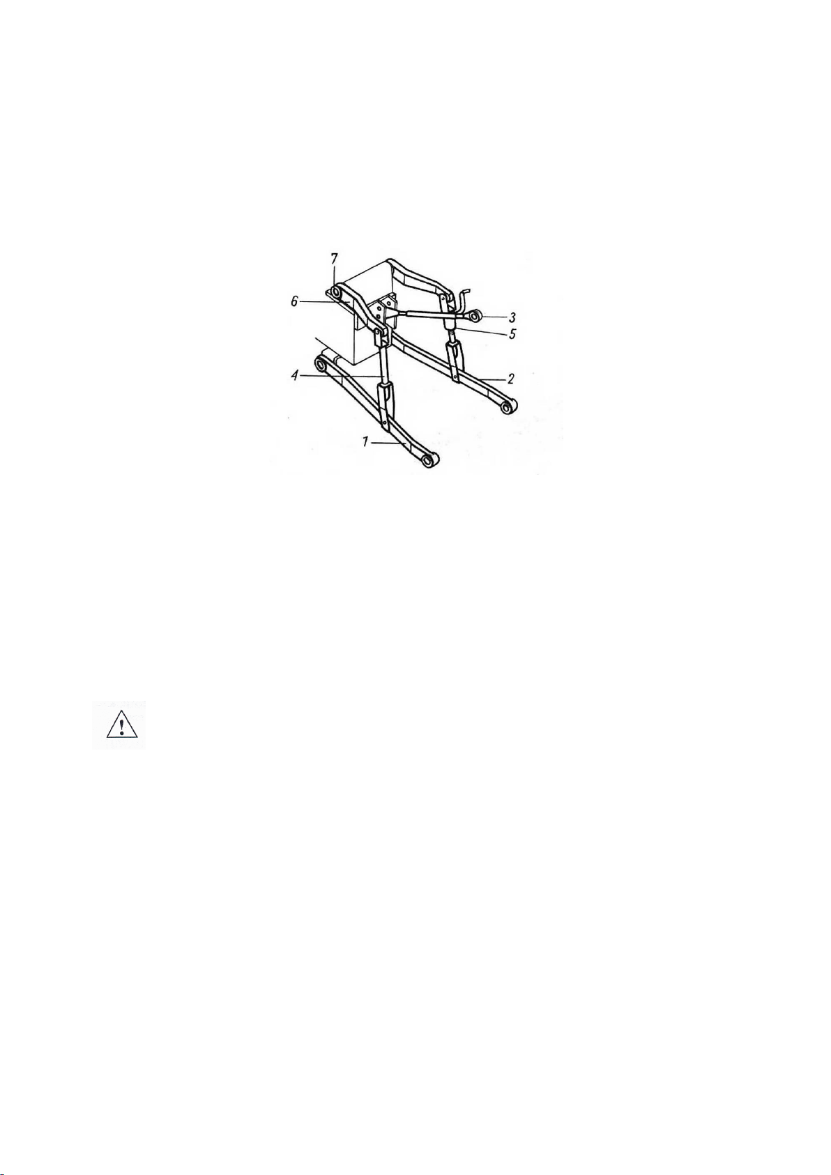
4.2. Hitching the cultivator with the tractor
Tyre pressure in the tractor wheels must comply with the values recommended by
the manufacturer. The lower bars of the three-point hitch should be at the same height,
spaced correspondingly to the spacing of the lower points of hitch. While attaching the
cultivator to the tractor, the machine must be placed on hard and even ground.
Fig. 11 Three-point hitch of the tractor: 1,2 – lower bars, 3 – upper fastener, 4 – left support rail, 5 – right support rail
with adjustable length, 6 – lift arm, 7 – lift shaft.
While attaching the cultivator to the three-point hitch of the tractor, complete the
following steps:
•switch the tractor hydraulic system into adjustment position,
•remove lower hitch bolts (if the tractor lift is not equipped with hooks),
•drive forwards carefully, suspend the implement on the lower bars and secure,
•check the operation of cultivator lifting, lowering and the hydraulic system.
CAUTION! Hitching the tractor with the cultivator must be performed
carefully, at the tractor’s minimum speed! When hitching the implement,
make sure that no bystanders are present in the vicinity.
4.3. Operation and adjustment
In order for the cultivator to work effectively – as the owner wishes – it is necessary
to carry out the implement adjustments before starting work. It is possible to determine
the working depth of the beams, rollers and discs. Remember to adjust the implement
symmetrically to maintain sufficient stability during operation.
4.3.1. Hydraulic lock of side extensions
RHINO cultivators are equipped with a hydraulic lock of side extensions, requiring
no additional maintenance. The lock uses a mechanism consisting of an actuator and
hook, as well as a handle assembly with a locking bar.
18
Fig. 12 Hydraulic lock of side extensions.
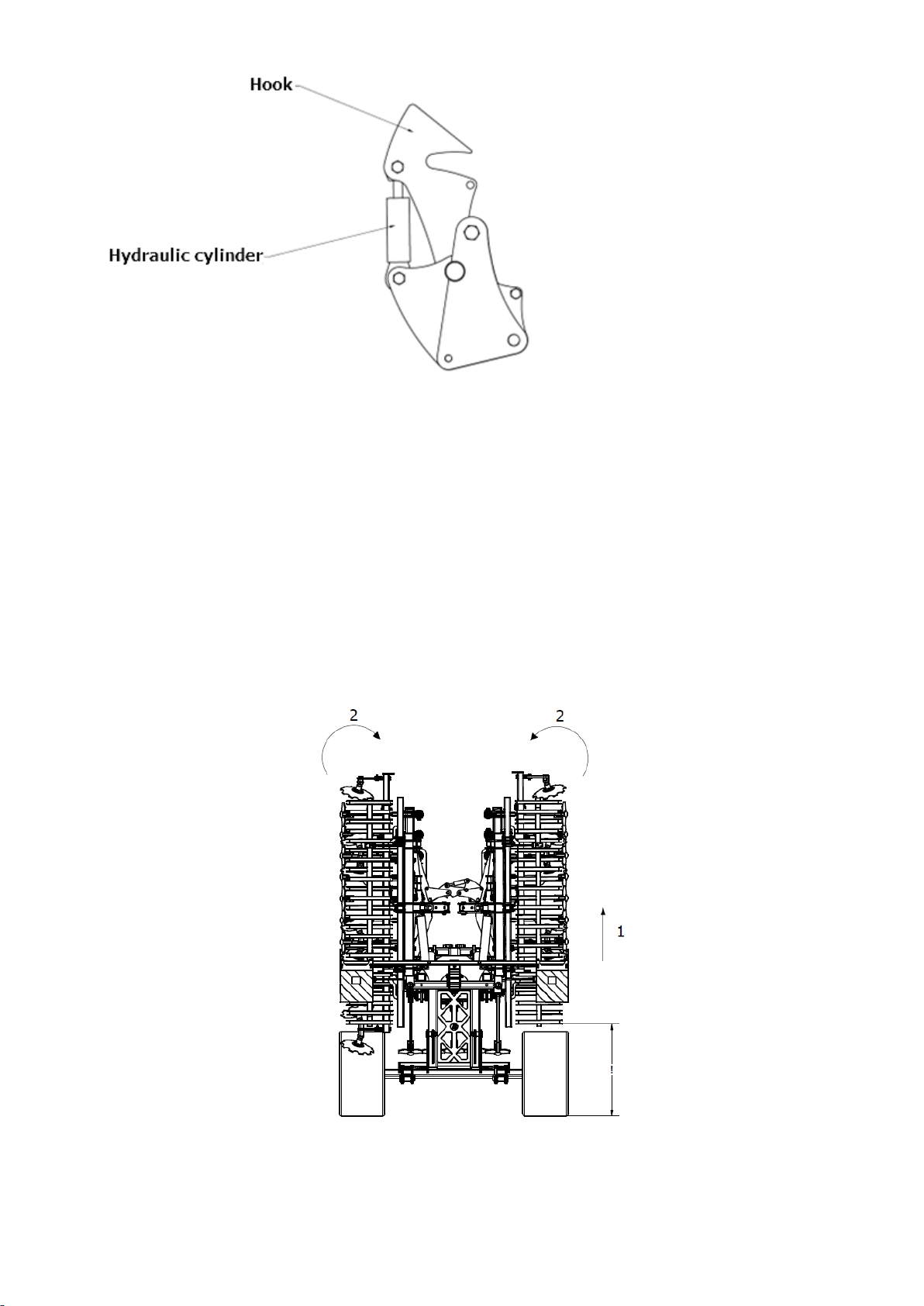
4.3.2. Implement opening sequence
Before unfolding the folding side the extensions of the machine, learn the opening
sequence to perform this operation correctly.
1. First, properly lower the chassis and raise the machine as much as possible to
allow the machine to be folded properly avoiding the risk of the folding arms
snagging on the ground during movement (Fig. 13).
2. Next, fold the implement side extensions hydraulically into the “closed” position
to ensure that the side extension lock mechanism will unlock and allow the
implement arms to be opened at a later stage. This operation is necessary each
time the arms are opened (Fig. 13).
Fig. 13 Implement opening sequence: 1- raise the implement up to the maximum, 2- fold the side extensions into the
“closed” position.

19
3. Then, after making sure that the hook of the hydraulic side extension lock
mechanism allows the machine side extensions to be unlocked, proceed to open
them fully (Fig. 14).
Fig. 14 Implement opening sequence: 3- release the hook of the hydraulic side extension lock mechanism, 4- open the
implement side extensions.
4. When opening the implement’s side extension arms, make sure that the ends of
the arms are at the correct height to prevent them from snagging on the ground
(Fig. 15).
Fig. 15 Implement opening sequence: open the implement paying particular attention to the height of the arm ends
from the ground.

20
5. To complete the opening sequence of the implement side extensions, wait until
the hydraulic mechanism opens the arms to their end position. Do not interrupt
the opening process of the arm side extensions without ensuring that they are
fully open.
Fig. 16 View of the implement at the completion of the side extension opening sequence. The implement arms are
fully open.
CAUTION! On implements with folding side extensions, clean the machine
thoroughly after use so that excessive soil residues do not put additional
strain on the machine side extensions and thus on the cylinders!
4.3.3. Beam position adjustment
The operation of the beams can be adjusted by changing their working angle and
depth. The depth of the beams is adjusted by changing the height of the support wheels
and the working angle by the nut on the spring bolt.
Support wheel position adjustment
The position of the support wheels is adjusted by means of an actuator – by
increasing its extension the working depth of working tools is reduced.
Table of contents
Other Mandam Farm Equipment manuals

Mandam
Mandam MGP Series User manual

Mandam
Mandam ORKAN VARIO Series User manual

Mandam
Mandam GAL-C User manual

Mandam
Mandam MCH Series User manual

Mandam
Mandam Hybro 3,0 User manual

Mandam
Mandam KNIFE ROLLER 3.0 User manual

Mandam
Mandam MWC Series User manual

Mandam
Mandam MBS User manual

Mandam
Mandam SPEC HD 2,5 User manual

Mandam
Mandam BTH-D User manual


Popular Farm Equipment manuals by other brands

Schaffert
Schaffert Rebounder Mounting instructions

Stocks AG
Stocks AG Fan Jet Pro Plus 65 Original Operating Manual and parts list

Cumberland
Cumberland Integra Feed-Link Installation and operation manual

BROWN
BROWN BDHP-1250 Owner's/operator's manual

Molon
Molon BCS operating instructions

Vaderstad
Vaderstad Rapid Series instructions


