Mandam ORKAN VARIO Series User manual
P.P.H. MANDAM Sp. z o.o.
44-100 Gliwice ul.Toruńska 2
e-mail [email protected]
Tel.: 032 232 26 60 Fax: 032 232 58 85
NIP: 648 000 16 74 REGON: P – 008173131
INSTRUCTION MANUAL
ORKAN VARIO PLOUGH
1st Edition
Gliwice 2017
1

ORKAN VARIO PLOUGH
Type/model:…..........................................................
Year of manufacture:............................................
Serial no.:…...............................................................
EC DECLARATION OF CONFORMITY
FOR THE MACHINERY
In accordance with the Ordinance of the Minister of the Economy dated 21 October 2008 (Journal of
Laws No. 199, item 1228)
and European Union Directive No. 2006/42/EC dated 17 May 2006
Przedsiębiorstwo Produkcyjno-Handlowe „MANDAM” Sp. z o.o.
ul. Toruńska 2
44-100 Gliwice
hereby declares, taking full responsibility that the following machinery:
to which this declaration refers meets the following requirements:
The Ordinance of the Ministry of the Economy dated 21 October 2008 on the
essential requirements for machinery (Journal of Laws No. 199, item 1228)
and European Union Directive No. 2006/42/EC dated 17 May 2006
Persons responsible for the machinery’s technical documentation: Jarosław Kudlek, Łukasz Jakus
ul. Toruńska 2, 44-100 Gliwice
The following standards were also used for the purpose of conformity assessment:
PN-EN ISO 13857:2010,
PN-EN ISO 4254-1:2009,
PN-EN ISO 12100-1:2005/A1:2009
PN-EN ISO 12100-2:2005/A1:2009
PN-EN 982+A1:2008
The present EC declaration of conformity will no longer be valid if the machinery is modi-
ed or rebuilt without the manufacturer’s consent.
Gliwice 14.12.2015 ………………………………………
Place and date of issue First and last name, position held
and signature of the person authorized
2

Contents
1 Introduction..........................................................................................4
1.1.Safety markings.................................................................................5
2 General information.................................................................................7
2.1.Construction of the ORKAN VARIO plough..................................................7
2.2.Intended use of the ORKAN VARIO plough..................................................8
3 General safety precautions.......................................................................10
3.1.Hitching and unhitching to a tractor.......................................................11
3.2.Tyres............................................................................................11
3.3.Hydraulic system..............................................................................12
3.4.Transporting on public roads................................................................12
3.5.Description of residual risk..................................................................14
3.6.Residual risk assessment.....................................................................14
4 Plough and tractor settings.......................................................................15
4.1.Preparing the plough.........................................................................17
4.2.Selection of the hitching bar................................................................17
4.3.Hitching the plough to the tractor.........................................................17
4.4.Adjustment of the hitching bar height....................................................18
4.5.Adjustment of the furrow width............................................................18
4.6.Adjusting the rst ridge......................................................................19
4.7.Levelling........................................................................................20
4.8.Adjusting the furrow depth.................................................................20
4.9.Rolling coulter.................................................................................21
4.10.Plough share.................................................................................22
4.11.Skim coulter..................................................................................22
4.12.Soil compactor arm.........................................................................23
4.13.Assembly and dismantling of the end pair of plough bodies.........................24
5 Operating the ORKAN VARIO plough.............................................................24
5.1.Lubrication.....................................................................................24
5.2.Worn out components........................................................................25
5.3.Securing bolts..................................................................................26
5.4.Gauge wheel...................................................................................26
5.5.Hydraulic system..............................................................................27
6 Storing the ORKAN VARIO plough................................................................28
7 Dismantling and disposal..........................................................................28
8 Technical characteristics..........................................................................28
9 General rules governing the warranty procedure.............................................29
WARRANTY CARD......................................................................................30
3

1 Introduction
We sincerely congratulate you on purchasing the ORKAN VARIO plough.
This instruction manual provides information on the hazards that may occur
during use, plough operation, technical data and the most important indications and
recommendations, the knowledge and use of which is a prerequisite for proper operation.
Keep this instruction manual for future reference. If you do not understand any provisions
of this instruction manual, please contact the manufacturer.
Recommendations that are important for safety reasons are marked with the following
sign:
Machine identication
Identication data concerning the plough are to be found on the nameplates located
on the support frame, which includes a CE marking, and basic information about the
manufacturer and the machinery:
The plough’s warranty is valid for 24 months from the date of sale.
The warranty card is attached hereto and placed on the last page of this instruction manual.
The warranty card constitutes an integral part of the machinery.
Always provide the serial number when submitting inquiries for spare parts.
Spare parts information:
• website: http://mandam.com.pl/parts/
• phone: +48 668 662 289
• e-mail: [email protected]
4
1.1. Safety markings
WARNING! When using this piece of machinery, special care must be taken in
areas marked with special information and warning signs (yellow stickers).
Below are the characters and inscriptions placed on this piece of machinery. Safety signs
and inscriptions should be protected from loss and illegibility. Signs and inscriptions that
become lost or illegible should be replaced by new ones.
Table 1. Information and safety markings.
5
Safety marking Meaning of the safety
marking
Place located on the piece of ma-
chinery
Read the instruction
manual before use.
Frame near xing of the upper
connector
Danger of toes or feet
being crushed.
Frame near xing of the upper
connector
Keep a safe distance from
holding parts and pieces of
machinery in motion The rear of the frame

Safety marking Meaning of the
safety marking
Stream of liquid under
pressure – risk of injury
Place for attachment of
transport belts
Place located on the piece
of machinery
Actuators
Upper section of hitching bar
(upper link bolt)
6
sheer bolt
plough
standard
mouldboard
breast
chisel
plough share
mouldboard
wing
2 General Information
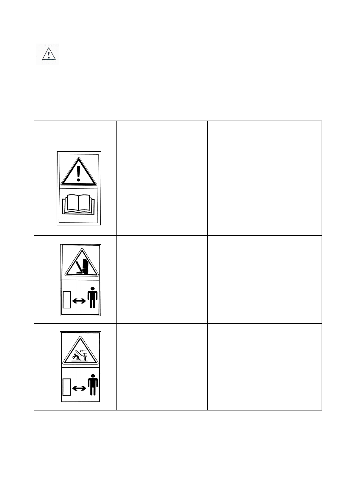
2.1. Construction of the ORKAN VARIO plough
The ORKAN VARIO plough’s construction: 1-head; 2-connector; 3-actuator for smooth
adjustment of VARIO’s furrow width; 4-gauge wheel; 5-plough body handle; 6-plough body;
7- main frame; 8-rolling coulter.
7

2.2. Intended use of the ORKAN VARIO plough
The ORKAN VARIO plough is designed to plough soils containing few stones. Its purpose is to
cut up eld’s earth, lift and turn it over in order to cover over crop residue and to loosen the soil.
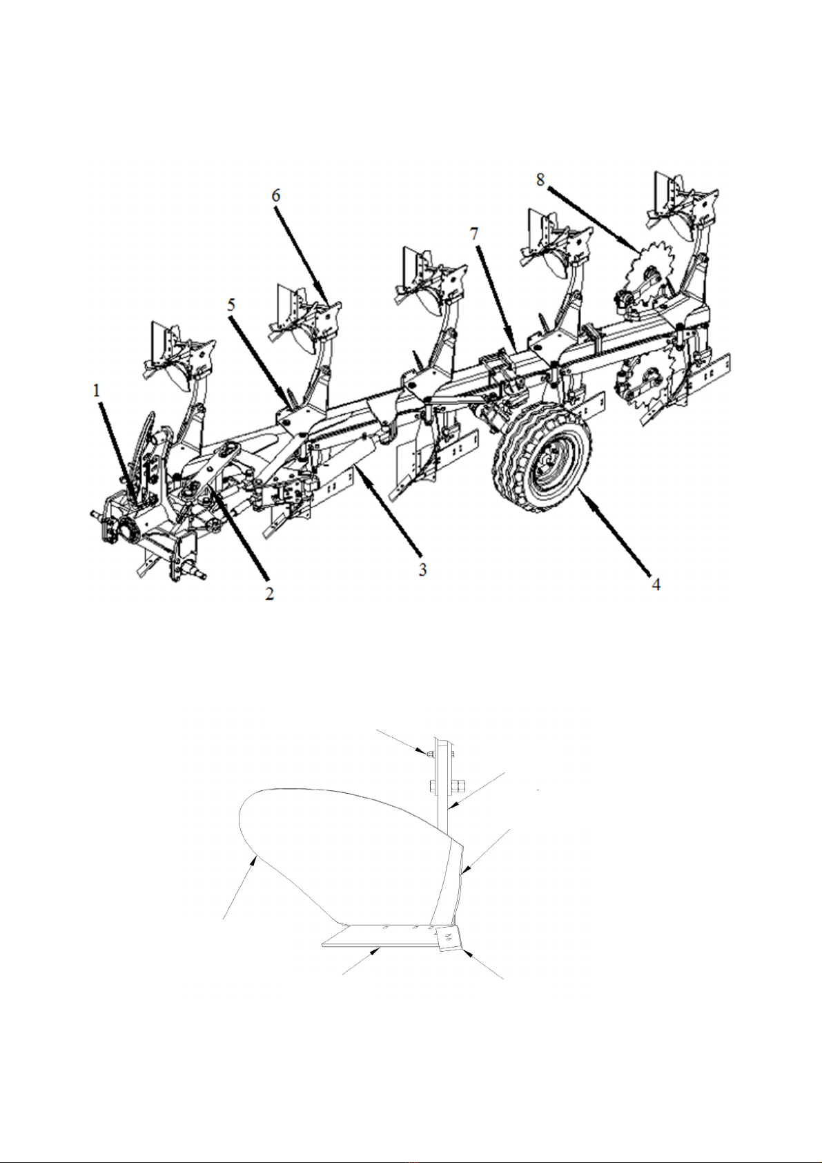
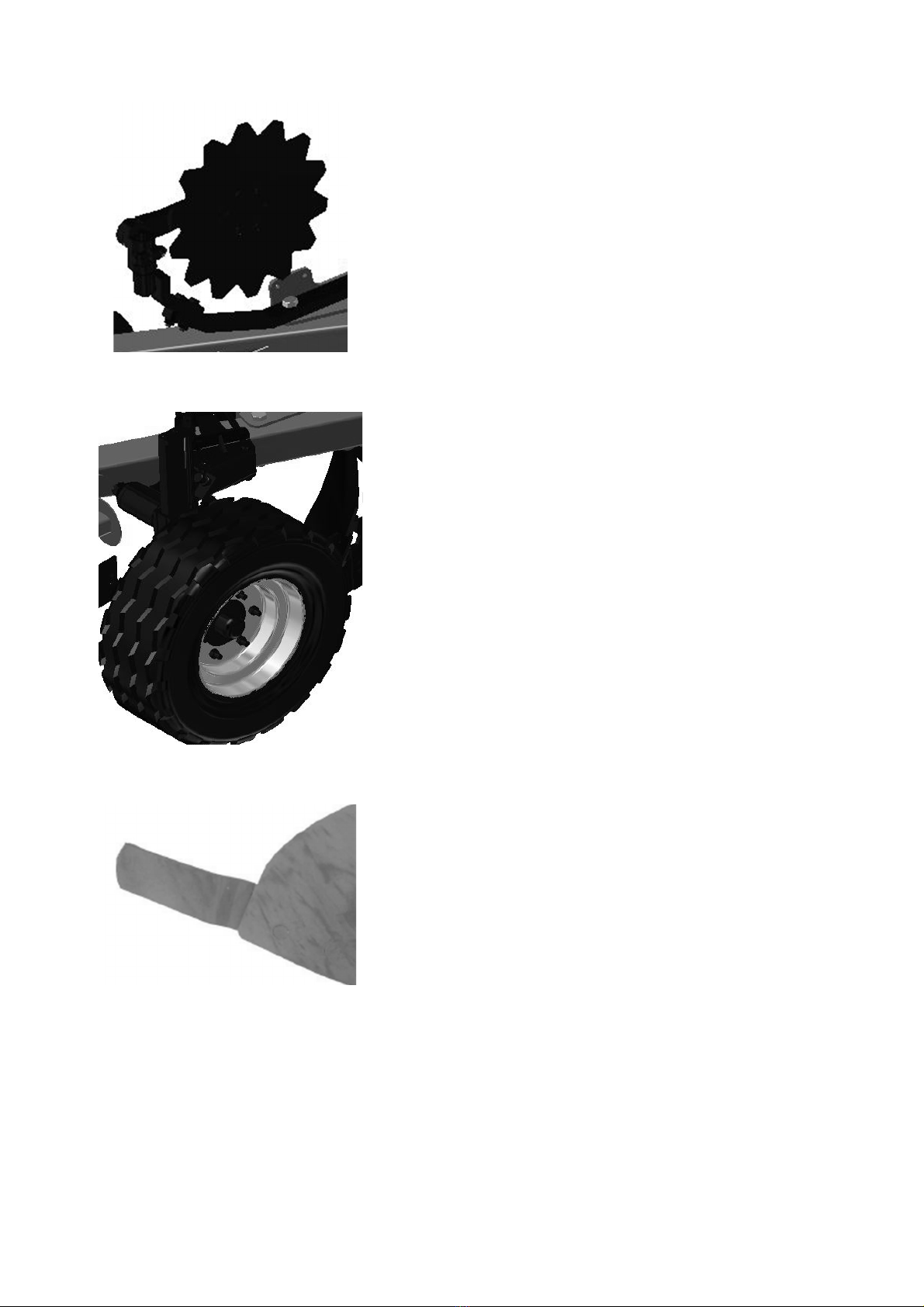
Its working elements are right- and left-hand plough bodies equipped with “18”
shares, reversible chisels, and full half-screw or openwork cylindrical mouldboard
Table 2. Description of the individual working components of the ORKAN VARIO plough.
Full half-screw mouldboard
Recommended for medium and light soils. Ideal for
covering over crop residues and characterized by a low
soil loosening intensity. It creates a wide furrow, which
allows it to be used in cooperation with tractors having
wide tires.
Openwork cylindrical mouldboard
Recommended for heavy (compacted) soils. Ideally
loosens the soil and thanks to the mouldboard being
of an openwork structure, ploughing resistance is
reduced.
Scraper (trash board)
Provides good coverage of crop residues and organic
fertilizers. Allows for a large space to be maintained
between the plough bodies.
Skim coulter
Recommended for ecient deep ploughing on soils with
a large amount of crop residues and stubble (especially
corn for medium to shallow ploughing) and organic
fertilizers
8
Gauge wheel
Shin
The rolling coulter is mounted on the end pair of plough
bodies to ensure a suitable furrow shape. It puts up
lower operating resistances compared to the knife cut
form of ploughing.
This ensures furrow depth is maintained and longitudinal
ploughing to ensure uniform depth of the furrow,
regardless of surface irregularities.
This ensures correct arrangement of the furrow especially
during the ploughing of stubble and areas covered by sod.
9
Rolling coulter

Alternative to the rolling coulters when reduction of
mass is necessary. It is also recommended for large
quantities of crop residues, organic fertilizers or stony
soils when a rolling coulter would be blocked
WARNING! This plough is exclusively intended for agricultural work - soil
cultivation. Using it for other purposes will be construed as improper use
and will result in loss of warranty.
WARNING! The manufacturer is not responsible for damage caused by
misuse of the machinery. Failure to comply with the instruction manual
will also be construed as misuse.
3 General safety precautions
The plough can only be started, used and repaired by persons familiar with its
operation and that of the tractor being used and the rules for its safe use and operation.The
manufacturer will not be responsible for any arbitrary modications of the construction of
the plough. Only “MANDAM” factory parts should be used during the warranty period.The
plough should be operated with caution and in particular:
• Before starting each ploughing operation, check the plough and the tractor whether
their condition guarantees safety during operation and travel,
• It is forbidden for the agricultural machinery to be used by a minor, anyone sick, or
after drinking alcohol or using other intoxicants,
• During work on this plough, one should use appropriate clothing, footwear and work
gloves,
• Do not exceed the permissible axle loads, tire pressures or transport dimensions,
• Only original pins and cotters should be used,
• Do not approach the plough while it is being lifted or lowered,
• Do not stand between the tractor and the plough when the engine is running,
• Driving the agricultural machinery, or raising and lowering it must be performed
slowly and gently without violent jerks, making sure that no bystanders are close to
the machinery,
• Do not reverse the tractor or make turns when the agricultural machinery is lowered
into the operating position,
10
Coulter

• Do not use the tractor’s independent brakes while making turns,
• Do not stand on the agricultural machinery or add any additional loads when it is in
operation or being transported,
• Take special care when making turns if bystanders are close by,
• Do not operate the plough on inclinations greater than 12º,
• Only make repairs, lubricate or clean the working parts with the tractor engine
turned o and the plough lowered,
• Do not carry out maintenance or replacement of parts beneath the agricultural
machinery without proper protection, as head injuries may occur - use a hardhat,
• During breaks in its operation the agricultural machinery should be lowered to the
ground and the tractor engine turned o,
• The plough is equipped with a mechanical lock that blocks the plough’s uncontrolled
rotation during transport,
• Driving and parking this machine on sloping unstable ground may lead to its slipping,
• Maintain the agricultural machinery in a manner that prevents injury to humans and
animals.
3.1. Hitching and unhitching to a tractor
• Make sure that the plough is connected to the tractor in accordance with the
instructions, remembering to secure the bolts and that the bolts are secured with
cotter pins.
• During towing of the plough by tractor it is forbidden to get between the agricultural
machinery and the tractor.
• The tractor working with the plough must be fully operational. It is prohibited to
connect this piece of machinery with a tractor with a hydraulic system that is not
fully operative.
• One must remember to keep the tractor’s balance with the plough and maintain its
steering and braking ability - the front axle load must not fall below 20% of the total
axle load of the tractor – use the set of front end counterweights.
• In a resting position, the agricultural machinery should maintain a stable equilibrium
and be disconnected from the tractor.
• The plough’s support stand should rest on stable ground. It is forbidden to use pads
under the support as this may cause instability.
3.2. Tyres
• The tyre pressure must not exceed the tyre manufacturer’s recommended tyre
pressure rating (as indicated on the tyre wall).
• Badly damaged tyres (especially damage to the prole) must be replaced
immediately.
• Repair work on wheels or tyres should be carried out by trained and authorized
personnel. These jobs should be carried out using appropriately selected tools.
11

lock lever
3.3. Hydraulic system
The hydraulic system works under high pressure. All precautions must be taken and in
particular:
• Do not connect or disconnect hydraulic lines when the hydraulic system of the
tractor is under pressure (hydraulics set to neutral).
• Regularly check the condition of connections and hydraulic lines,
• When repairing any hydraulic breakdown, the plough should be disconnected from
its power source.
3.4. Transport on public roads
For transporting the plough, it should be turned to the middle position (the frame should
be on the same axis as the tractor), then locked with the bolt. Prior to being rotated,
lift the plough to a level where it will not come into contact with the ground. During
transportation, the clearance under the lowest part of the plough should prevent it from
coming into contact with the ground during transportation on uneven surfaces. When
taking the plough onto public roads, it is mandatory to use driving lights, a distinctive
warning sign and side reectors.
Do not exceed the appropriate speed limits during transportation, which are:
• up to 20 km/h on roads with smooth asphalt surfaces
• 6-10 km/h on country roads or cobblestones
• not more than 5 km/h on bumpy roads
The driving speed must be adjusted to the road conditions and conditions prevailing on
the road so that the plough does not jerk the tractor’s suspension system and there is no
excessive load on the plough’s frame or tractor’s suspension.
Take special precautions when passing other vehicles, overtaking, and turning. The
permissible width of the agricultural machinery moving on public roads is 3.0 m.
It is forbidden to transport the plough over any area where the inclination of the slope
transversely to the plough exceeds 7º.
Be aware of the length of the plough. On sharp turns the plough turns in the opposite
direction to the direction of the turn. This may result in a collision with obstacles or other
road users.
During transport the plough is to be secured
with the lock that keeps the plough on the
same axis as the tractor, reducing its transport
width and increasing the stability of the
vehicle during transport. For locking, use the
lever that you need to turn so that it jumps
out of its slot and so that the pin holds the tow
bar head in the locked position. Once locked,
the plough cannot be turned because damage
to it may occur. To unlock, turn the lock lever
so that it falls back into its slot.
12

support
stand
safety pin
When the plough is parked, the support stand
must be secured to stop the plough overturning.
To this end, pull the safety pin, then take hold
of the support stand’s handle and pull it toward
you. Turn the support stand to the support
position (a 90º rotation) and release the handle.
WARNING! Take care when transporting the plough. It is forbidden to travel
on public roads without appropriate additional warning signs.
Thoroughly clean the agricultural machinery of all crop residues and earth before travelling
on a public road. Portable warning lights and a distinctive warning sign for slow-moving
vehicles (according to current trac regulations) should be mounted on the end of the
plough’s frame.
During transportation the plough should be raised to such a height that the minimum
clearance under the agricultural machinery is a minimum 25 cm.
WARNING! Moving this plough on public roads without warning signs and lights
required by the trac regulations may be dangerous and cause an accident.
WARNING! Warning signs and lights are not part of the plough’s equipment.
You can purchase them at points of sale for agricultural machinery.
Warning! Failure to adhere to the above may present a risk to the operator
and bystanders, as well as cause damage to the agricultural machinery. Any
damage resulting from non-compliance with these rules is the responsibility
of the user.
13

3.5. Description of residual risk
MANDAM sp. z o.o. makes every eort to eliminate the risk of accident. However,
there is a degree of residual risk that may cause an accident. The greatest danger occurs
when:
• using the agricultural machinery for purposes other than those described in the
instruction manual,
• the agricultural machinery is used by minors without permission, by anyone that is
sick, or under the inuence of alcohol or other intoxicants,
• people or animals come too close to the agricultural machinery,
• insucient care is taken when transporting and manoeuvring with the tractor,
• anyone gets between the agricultural machinery and the tractor while the tractor’s
engine is running,
• the plough is in operation or when its instruction manual are ignored,
• travelling on public roads.
3.6. Residual risk assessment
Residual risks can be minimized by following the recommendations below:
• careful operation of the agricultural machinery without undue haste,
• careful reading of the instruction manual,
• maintaining a safe distance from hazardous areas,
• adhering to the rule about not riding on the agricultural machinery or coming too
close to the moving parts of the agricultural machinery while the tractor engine is
running,
• performing all maintenance work in accordance with the safety precautions,
• using protective clothing and, if any work needs carried out beneath the agricultural
machinery, wearing of a hardhat,
• preventing unauthorized access to this piece of machinery, especially children.
14
0-10 cm greater than the rear
tyres
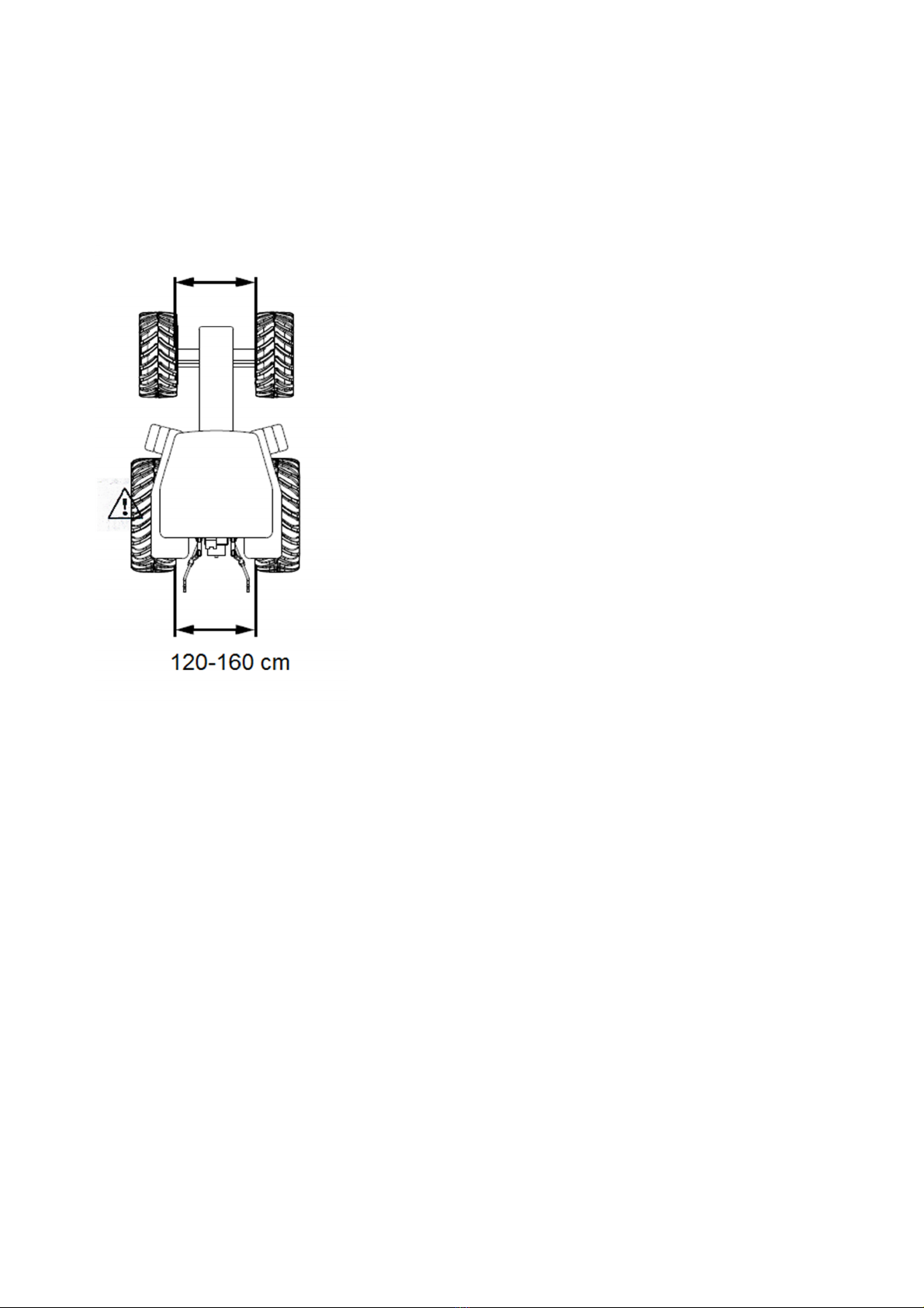
4 Plough and tractor settings
The tractor selected for use with this plough should have the characteristics described in
the following paragraphs. The hydraulic system must be ecient and have two pairs of
hydraulic couplings in accordance with ISO 7241-1 A, controlled by a twin distributor. The
pressure in both rear tyres of the tractor should be the same value to avoid the formation
of uneven ridges.
Recommendations for the tractor:
• The recommended distance between the far inner
points of the rear tyres (without the use of a furrow
extender) should be 120 - 160 cm,
• The recommended distance between the far inner
points of the front tyres should be 0 - 10 cm greater
than for the rear tyres
WARNING! The permissible loads on the axles and tyre
load capacities must not be exceeded. The front axle
load may not be less than 20% of total axle loads.
15
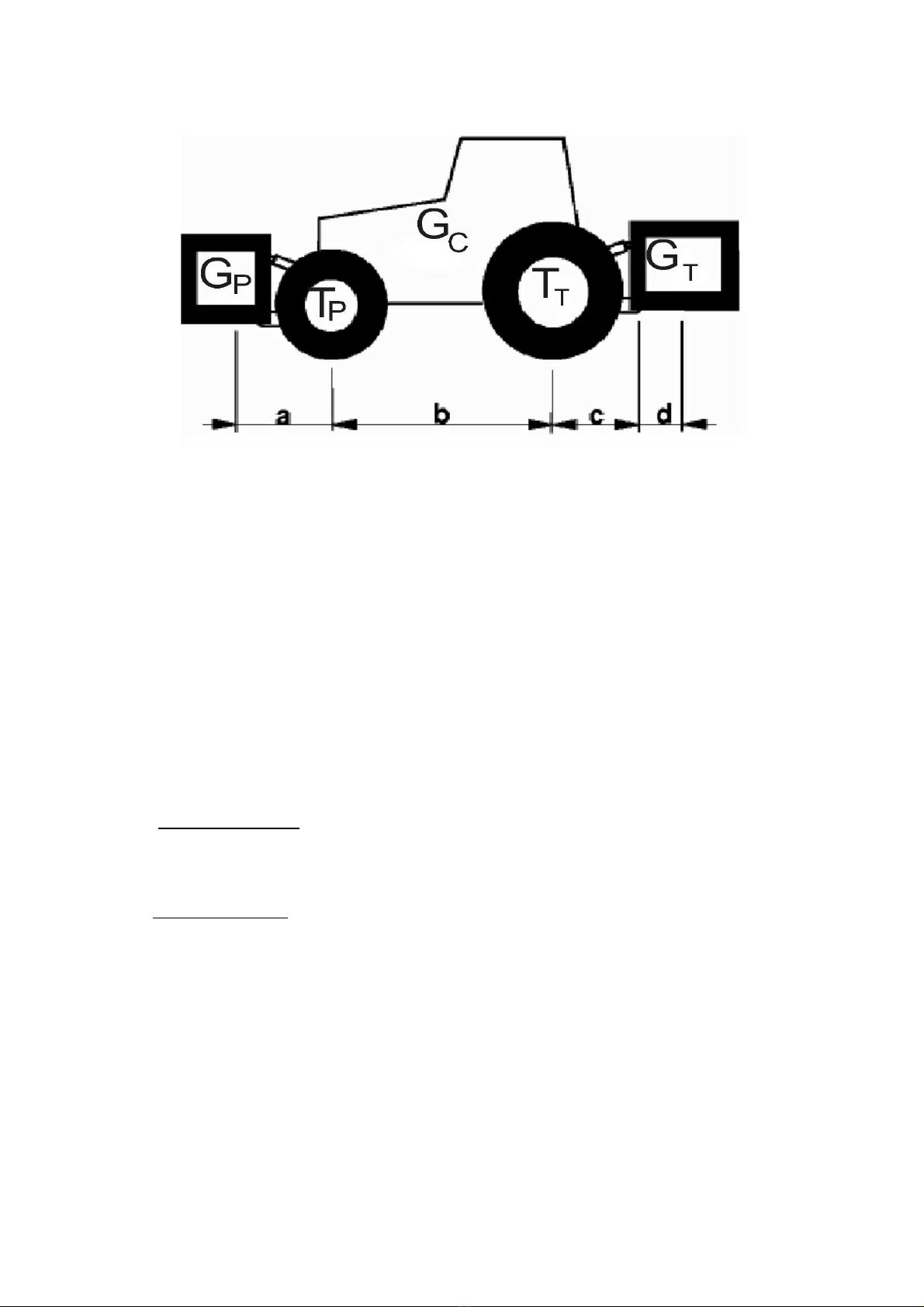
Axle load calculations
Signs:
GC – the tractor’s gross weight,
TP – front axle load for the unhitched tractor,
TT – rear axle load for the unhitched tractor,
GT – total weight of the equipment attached at the back,
GP – total weight of the equipment attached at the front,
a – the distance between the centre of gravity of the equipment attached at the front
and the centre of the front axle,
b – wheelbase of the tractor,
c – the distance between the centre of gravity of the rear axle and the centre of the
hitching pin of the equipment at the back,
d – the distance from the centre of gravity of the agricultural machinery to the hitching
pins of the tractor,
x – the distance of the centre of gravity from the rear axle (if the manufacturer does not
specify, one should make this 0.45).
The minimum front load when attaching the agricultural machinery to the rear of the tractor:
GPmin= GT⋅cd−Tp⋅b0,2⋅GC⋅b
ab
Actual load on front axle:
TPtot= GP⋅(a+b)+Tp⋅b−GT⋅(c+d)
b
Actual total weight:
Gtot=GPGCGT
Actual load on rear axle:
TTtot=Gtot−TPtot
16
wrong
4.1. Preparing the plough
The plough is usually delivered ready to be used. Due to transport limitations, it
may also be at times delivered partially dismantled. Check the technical condition of the
plough, especially the moving parts and all bolt connections, before commencing work.
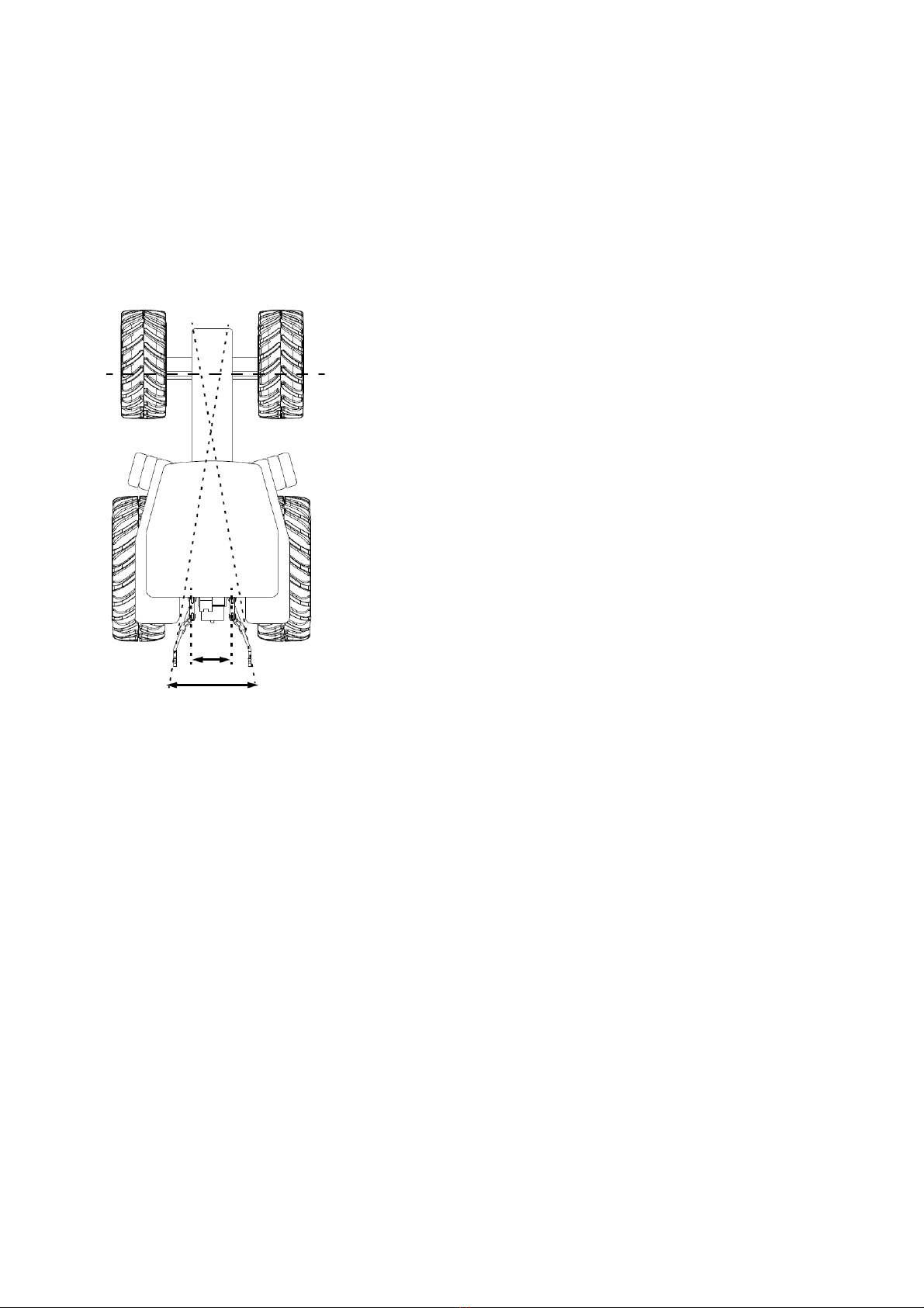
4.2. Selection of the hitching bar
In order to obtain a rst ridge of a stable width, the
theoretical line of intersection of the lower connectors of
the tractor’s suspension system should be at the distance
of 1/3 of the tractor’s wheelbase behind the front axle.
Failure to do this may cause the plough to “slew”. In such
a case, a hitching bar of a dierent length must be used.
4.3. Hitching the plough to the tractor
The TUZ lower connectors should be at the same height, spaced apart by a distance
corresponding to the space between the lower plough suspension points. When hitching the
plough to the tractor, the agricultural machinery should stand on a hard and level surface.
When hitching the two pieces of machinery together the following must be carried out:
• Suspend the hitching bar on the lower connectors of the TUZ and secure with cotter pins,
• Switch the hydraulic system of the tractor to the positioning adjustment,,
• Carefully reverse and hitch the agricultural machinery onto the hitching bar and then
secure it with the bolts,
• Connect the tractor’s upper connector (when the plough is in operation the xing
point of the upper connector on the plough should be positioned higher than the
xing point of that connector on the tractor),
• Check the raising, lowering and overall operation of the plough’s hydraulic system.
17
smaller
ploughs
larger ploughs
handle openings
handle bolts
hitching bar
hitching bar
handle
Connection of upper connector:
• Oval (longitudinal) holes allow for better
longitudinal ploughing of the terrain. Use for
4-5 furrow plough, in extreme cases 3-furrow
plough.
• A xed hole prevents the plough from rising up
on heavy and stony soils. Use for 2-3 furrow
ploughs.
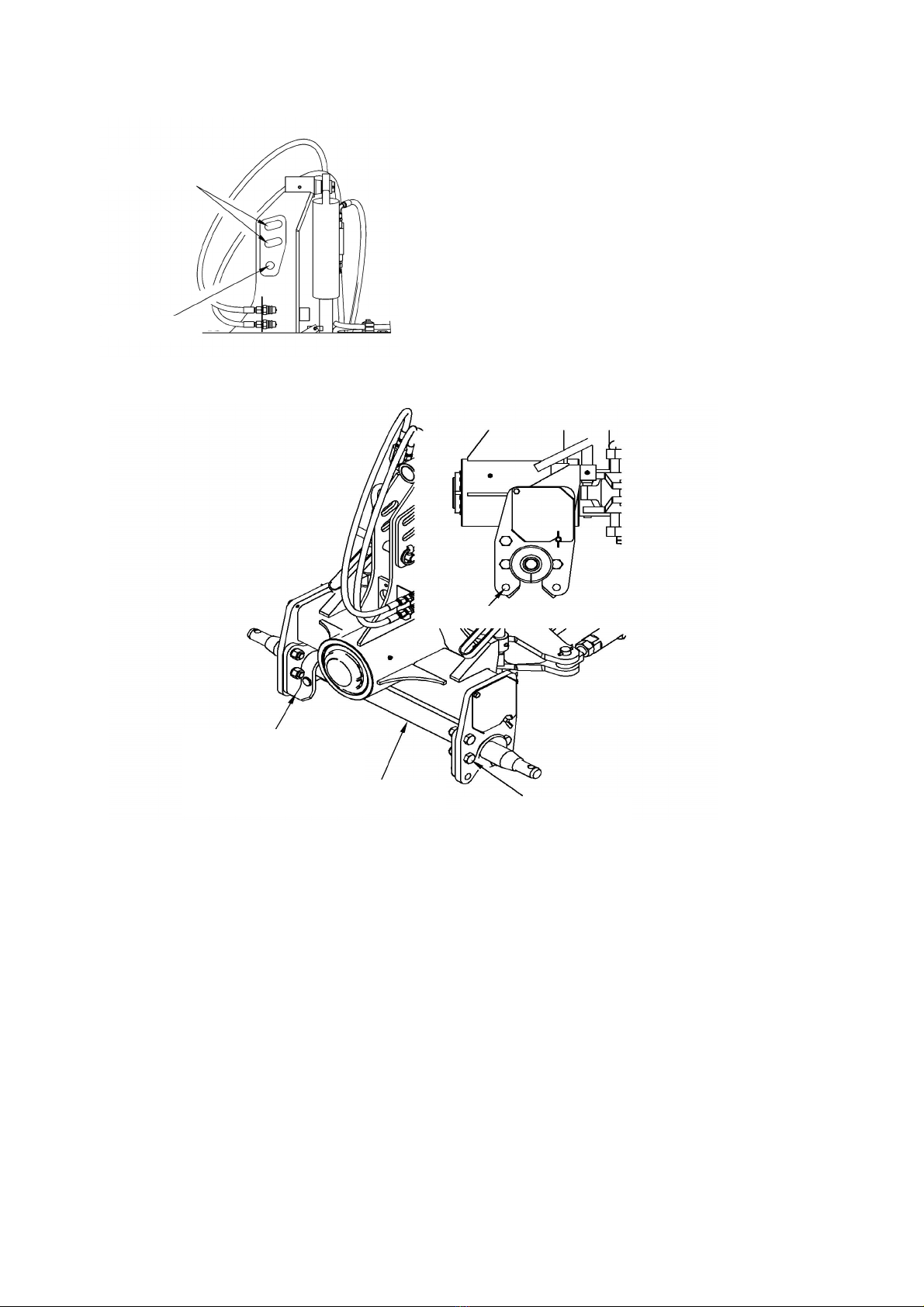
4.4. Adjustment of the hitching bar height
The hitching bar can be set at the height of 64.5 cm and 57 cm from the ground depending
on the type of tractor operating the plough. In order to change the position of the hitching
bar, rst remove the hitching bar from the plough’s suspension system. Then turn the
hitching bar handle to the appropriate holes.
4.5. Adjustment of the furrow width
The ORKAN VARIO plough is equipped for an innitely adjustable furrow width. Changing
the furrow width is possible thanks to the use of a hydraulic actuator. The furrow width
can be smoothly adjusted, i.e. without steps, anywhere from 30 to 50 cm. The arrow in
the photo below shows the position of the furrow width adjustment actuator and its view
as seen from above.
18
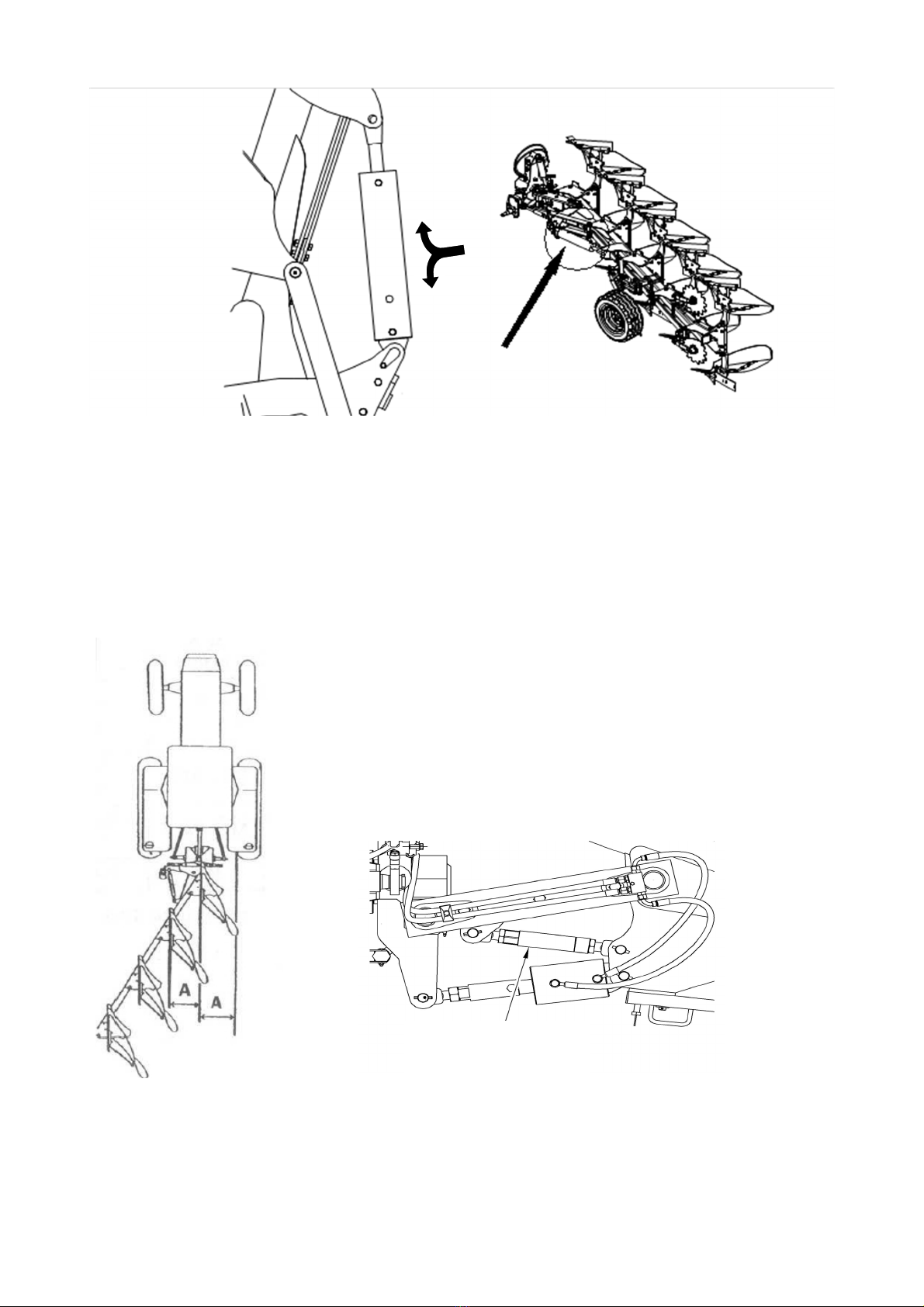
bolt for adjustment
of the width of the rst ridge
Setting the optimum furrow width is of particular importance for reducing the working
resistance of the agricultural machinery and minimizing the degree of soil clumping
after ploughing. The operating width of a plough body must be adjusted according to
the weather conditions, terrain and the capabilities of the farm tractor. Indicated above
is the position of the actuator within the agricultural machinery and the direction of
its movement. Extension of the actuator reduces the furrow width, while the maximum
position of the actuator corresponds to the maximum furrow width.
4.6. Adjusting the rst ridge
The width of the rst ridge should correspond to the width of
the remaining ridges, but one should also take into account:
• resultant compensation of the plough’s operating resistance,
• with wide tractor tyres, the width of the rst ridge should
be reduced to ensure proper alignment of the front ridges,
• For a plough equipped with a furrow widener, the width of
the rst ridge should be reduced by 13 cm compared to the
width of the remaining ridges.
After altering the working width of the rst ridge, one may need to adjust the width of
the furrow.
19
transverse levelling
adjustment bolt
wheel adjustment
crank
4.7. Levelling
The plough is longitudinally levelled by means of the upper connector. The plough frame
should always be parallel to the ground. The upper connector bolt should be in the middle
of the longitudinal hole.
The plough is transversely adjusted using the bolts with
handles. There is separate adjustment for the left and
right sides. Looking at the plough from behind, the
plough’s beams should be positioned perpendicular to
the ground. With any change in the depth of the furrow,
a transverse levelling adjustment must be made
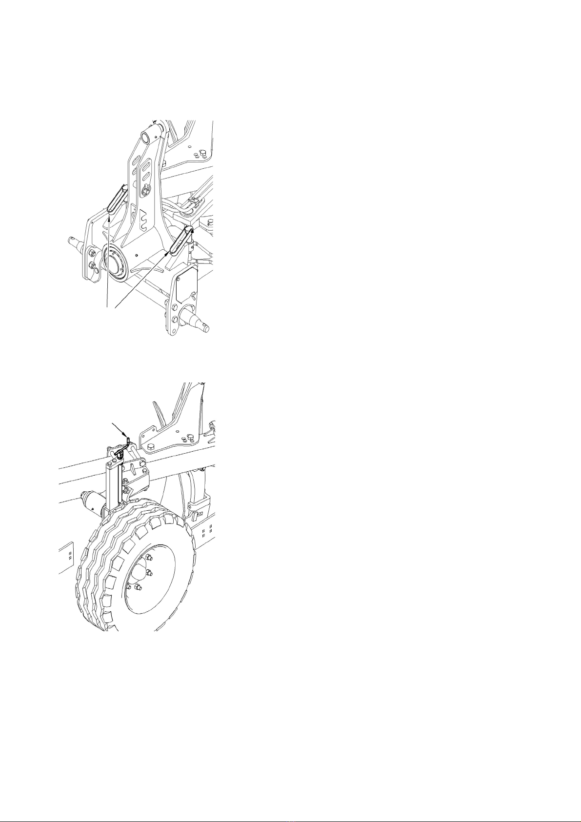
4.8. Adjusting the furrow depth.
When attaching the upper connector to the longitudinal
holes, it is necessary to set the furrow depth by means of
the tractor’s hydraulic (actuator/positional) regulation.
Setting the furrow depth on the gauge wheel is carried
out using a screw crank. The setting is the same for left
and right-hand side. Bumpers (screws with a counter nut)
allow the angle of the gauge wheel arm to be changed
relative to the ground. This allows you to change the
distribution of forces acting on the gauge wheel moving
over dicult terrain. Changing the angle of the gauge
wheel arm also results in the change to the depth of the
furrow.
20
This manual suits for next models
4
Table of contents
Other Mandam Farm Equipment manuals

Mandam
Mandam MGX 2200 User manual

Mandam
Mandam SAL DISC HARROW User manual

Mandam
Mandam SUPER User manual

Mandam
Mandam Hybro 3,0 User manual

Mandam
Mandam KNIFE ROLLER 3.0 User manual

Mandam
Mandam SPEC HD 2,5 User manual

Mandam
Mandam MBS User manual

Mandam
Mandam ORKAN 3+ User manual

Mandam
Mandam RHINO User manual

Mandam
Mandam GAL-K User manual


Popular Farm Equipment manuals by other brands

GREAT PLAINS
GREAT PLAINS BD7600 Original instructions

RITEWAY
RITEWAY ROCK PICKER 250 Operator's manual & parts

Land Pride
Land Pride CB1060 Operator's manual

AGT INDUSTRIAL
AGT INDUSTRIAL AGT-ECSSLR72 product manual

Wylie
Wylie Non-DOT Nurse Trailer Operator's & parts manual

Schlagel
Schlagel HD-1000 Series Operator's manual


