Mandam GAL-C User manual

1
MANDAM Sp. z o.o.
ul. Toruńska 14 44-100 Gliwice, Poland
e-mail: [email protected]
Tel.: 032 232 26 60 Fax: 032 232 58 85
NIP (VAT no.): 648 000 16 74 REGON (Registration no.): P – 008173131
INSTRUCTION MANUAL
GAL-C, GAL-E, GAL-S DISC HARROW
Issue III
Gliwice 2022

2
DECLARATION OF CONFORMITY
FOR A MACHINE
In accordance with the Ordinance of the Minister of the Economy dated 21 October 2008 (Journal of Laws No. 199, item
1228)
and the Directive of the European Union no. 2006/42/EC of 17 May 2006
MANDAM Sp. z o.o.
ul. Toruńska 14
44-100 Gliwice
hereby declares at its sole responsibility that the following machine:
under this declaration, complies with:
the Ordinance of the Ministry of Economy of 21 October 2008 on fundamental
requirements for machinery (Journal of Laws No. 199, item 1228)
and the Directive of the European Union 2006/42/EC of 17 May 2006.
The persons responsible for the technical documentation for the machine: Jarosław
Kudlek, Łukasz Jakus
ul. Toruńska 14, 44-100 Gliwice, Poland
For assessment of compliance the following standards have been applied:
PN-EN ISO 13857:2010
PN-EN ISO 4254-1:2016-02
PN-EN ISO 12100-1:2005/A1:2012
PN-EN ISO 12100-2:2005/A1:2012
PN-EN 982+A1:2008
This EC Declaration of Conformity shall be cancelled
if the machine is modified or redesigned without consent of the manufacturer.
……………………………………
………………………………………
Place and date of issue
First and last name, position held
and signature of the person authorized
GAL-C/GAL-E/GAL-S DISC HARROW
type/model: ……………………………
year of manufacture: ………………….
serial number: …………………………

3
1Introduction ................................................................................................................................4
1.1 Safety symbols and inscriptions ...........................................................................................5
2General information...................................................................................................................7
2.1 Design of the GAL-C disc harrow........................................................................................7
2.2 Intended use of the GAL- C disc harrow.............................................................................8
2.3 Design of the GAL-E disc harrow........................................................................................8
2.4 Intended use of the GAL-E disc harrow..............................................................................9
2.5 Design of the GAL-S disc harrow ......................................................................................10
2.6 Intended use of the GAL-S disc harrow ............................................................................11
3General safety information......................................................................................................12
3.1 Hitching and unhitching from a tractor............................................................................13
3.2 Tyres ....................................................................................................................................13
3.3 Hydraulic and pneumatic systems .....................................................................................13
3.4 Transport safety on public roads........................................................................................14
3.5 Residual risk description ....................................................................................................14
3.6 Residual risk assessment ....................................................................................................15
4Information on operation and use ..........................................................................................15
4.1 Preparation of the disc harrow ..........................................................................................17
4.2 Hitching the disc harrow with the tractor..........................................................................17
4.3 Hitching the sower with the disc harrow ...........................................................................18
4.4 Operation and adjustment..................................................................................................19
4.4.1 Automatic locking of the machine side extensions ..................................................19
4.4.2 Implement opening sequence ....................................................................................19
4.4.3 Setting the working units...........................................................................................21
4.4.4 Working depth of the GAL-C H disc harrow..........................................................27
4.5 Rules for transporting the harrow on public roads and lighting the implement .............28
4.6 Maintenance and lubrication.............................................................................................30
4.7 Screw tightening torque......................................................................................................30
5Maintenance..............................................................................................................................31
6Replacement procedures..........................................................................................................33
7Disc harrow storage .................................................................................................................35
8Disassembly and withdrawal from service and scrapping ...................................................35
9GAL disc harrow – spare parts...............................................................................................36

4
1Introduction
Congratulations on your purchase of the GAL disc harrow. This instruction
manual contains the information on hazards that may occur during operation, work with
the device, technical data and the most important guidelines and recommendations to be
known and applied to ensure a proper operation. Keep this manual for future reference.
Should you have any problems with understanding any statement in the instruction
manual, please contact the manufacturer.
The following mark indicates the guidelines that are important due to safety reasons:
Machine identification
Identification data of the GAL disc harrow, including basic information on the
manufacturer and the machine and CE marking, can be found on the rating plates placed
on the load-bearing frame:
The warranty for the harrow is valid for 12 months from the date of sale.
The warranty card constitutes an integral part of the machine.
Whenever you request any information on spare parts, provide the serial number.
For more information on spare parts,
•please visit our website at: http://mandam.com.pl/parts/
•call us at +48 668 662 289
•e-mail: [email protected]

5
1.1 Safety symbols and inscriptions
Remember! Remember! Be particularly careful in places marked with the
special information and warning symbols (yellow labels).
The following symbols and inscriptions can be found on the implement. Secure the
symbols, signs and inscriptions against loss and make sure they are legible at all times. If
lost or illegible, replace the signs and inscriptions with new ones.
Table 1. Information and warning signs.
Safety sign
Meaning of the safety sign
Location on the implement
Read the instruction manual
prior to operating the
implement.
Frame adjacent to the
mounting place of the upper
fastener
Danger of toe or foot crush
Frame adjacent to the
mounting place of the upper
fastener
Keep clear from lift bars
while controlling the lift
Frame adjacent to the
mounting place of the upper
fastener

6
Safety sign
Meaning of the safety sign
Location on the implement
Keep clear from foldable
and moving parts of the
implement
Front part of the central
frame adjacent to side
frames
Do not reach into the
crushing zone if the
elements can move
Central frame adjacent to
side frames
Pressurized fluid – hazard of
bodily injury
Cylinders
Fixing point for transport
belts
Upper part of the drawbar
(upper fastener bolt)
Rear part of the frame:
•rigid frame (adjacent
to the roller depth
adjustment)
•foldable frame
(adjacent to the
cylinder bolt on the
central frame)

7
2General information
2.1 Design of the GAL-C disc harrow
The GAL-C harrows are available in the following widths: 2.5 m, 3.0 m, 3.5 m, 4.0 m, 4.5
m, 5.0 m and 6.0 m.
Fig. 1 GAL disc harrow.

8
Table 2. GAL-C disc harrow types.
Harrow type
Working
width [m]
Tined disc
diameter [mm]
Number of
discs [pcs]
Disc row spacing
[mm]
Min. tractor
power [hp]
Weight [kg]
GAL-C 2.5
2.5
Ø560
20
900
80
1205
GAL-C 3.0
3.0
Ø560
24
900
100
1314
GAL-C 3.5
3.5
Ø560
28
900
120
1495
GAL-C 4.0
4.0
Ø560
32
900
140
1849
GAL-C 4.0 H
4.0
Ø560
32
1000
160
2215
GAL-C 4.5 H
4.5
Ø560
36
1000
170
2395
GAL-C 5.0 H
5.0
Ø560
40
1000
180
2586
GAL-C 6.0 H
6.0
Ø560
48
1000
200
2923
2.2 Intended use of the GAL- C disc harrow
The disc harrow is designed for post-harvesting (with crushed straw) and pre-sowing
cultivation in both plough and ploughless technology. The implement can also be used for
mixing aftercrop or uncultivated land with high self-sown plants with soil.
The working elements are tined discs with the standard diameter of Ø560 mm in
two shifted rows mounted on maintenance-free bearings. Equipping each disc with its own
bearing allows for an optimum inclination of the disc in relation to the direction of travel
and the ground. This allows the stubble to be accurately cut and ensures that the post-
harvesting crop residues are evenly mixed and ground. As a result, evaporation of the soil
is interrupted, plant residues decompose more quickly and the intensity of phenolic
compounds, which have a negative impact on the development of successive crops, is
reduced. Disc tines support plunging and penetrating the ground. A roller at the rear of
the implement compacts the soil, resulting in faster germination of weeds and self-sown
plants. The use of a disc harrow before sowing ensures a precise mixing of fertilisers with
the soil, an even surface and an appropriate soil structure.
GAL disc harrows can be equipped with transport chassis to facilitate tractor
transport.
2.3 Design of the GAL-E disc harrow
The GAL-E harrows are available in the following widths: 2.0 m; 2.5 m; 3.0 m.
Table 3. GAL-E disc harrow types.
Harrow type
Working
width [m]
Tined disc
diameter [mm]
Number of
discs [pcs]
Disc row spacing
[mm]
Min. tractor
power [hp]
Weight [kg]
GAL-E 2.0
2.0
Ø560
16
800
75
1200
GAL-E 2.5
2.5
Ø560
20
800
80
1347
GAL-E 3.0
3.0
Ø560
24
800
100
1500

9
Fig. 2 GAL-E disc harrow.
2.4 Intended use of the GAL-E disc harrow
The GAL-E version of the disc harrow, unlike the GAL-C version, uses arms on
cylinders to hydraulically lift the roller during transport. In addition, the axis distance of
the rows of working discs has been reduced to 800 mm resulting in smaller footprint and
facilitating transport and the manoeuvrability of the entire set.

10
Fig. 3 GAL-E disc harrow with raised roller.
2.5 Design of the GAL-S disc harrow
The GAL-S harrows are available in the following widths: 3.0 m.
Table 4. GAL-E disc harrow types.
Harrow type
Working
width [m]
Tined disc
diameter [mm]
Number of
discs [pcs]
Disc row spacing
[mm]
Min. tractor
power [hp]
Weight [kg]
GAL-S 3.0
3.0
Ø560
24
800
140
1500

11
Fig. 4 GAL-S disc harrow.
2.6 Intended use of the GAL-S disc harrow
The GAL-S version of the disc harrow has a coupling for mounting the seeder on the
machine supported by arms raised by a hydraulic system that allows lowering and raising
the seeder during transport (hydropack). In addition, the axis distance of the rows of
working discs has been reduced to 800 mm resulting in smaller footprint and facilitating
transport and the manoeuvrability of the entire set.

12
CAUTION! MANDAM grants a 5-year warranty on maintenance-free hubs
subject to the following conditions:
- the principle is observed of the working disc replacement in case of their
wear, which may not exceed the diameter of 490 mm for Ø560 mm and 550
mm for Ø610 mm discs,
- original MANDAM discs are used,
- the permissible working depth, which is 12 cm for Ø560 mm discs and 15
cm for Ø610 mm discs, is not exceeded,
- the principle is observed of no turning manoeuvre of the harrow when it is
in the working position (working discs recessed in the soil).
CAUTION! The disc harrow is designed for agricultural use only. Using the
implement for tasks that differ from the intended use shall be regarded as
misuse, resulting in loss of warranty. Failure to follow the guidelines included
in this instruction manual shall be regarded as misuse.
CAUTION! The manufacturer shall not be liable for any damage arising out of
misuse.
3General safety information
The disc harrow can be started, operated and repaired only by persons familiar
with its operation and with the operation of the attached tractor as well as knowing the
rules of safe operation and maintenance of the implement.
The manufacturer shall not be liable for any unauthorised alternation of the harrow. Only
genuine MANDAM spare parts shall be used during the warranty period.
The disc harrow must be operated with all precautionary measures and due care, in
particular:
•before every start-up check the disc harrow and the tractor, make sure that their
conditions guarantee safety of traffic and operation;
•minors, disabled or intoxicated persons (under the influence of alcohol or drugs)
must not operate the machine,
•during operation and maintenance wear working clothes, footwear and gloves,
•do not exceed the maximum axle loads and transport dimensions,
•use only original cotter pins and pins,
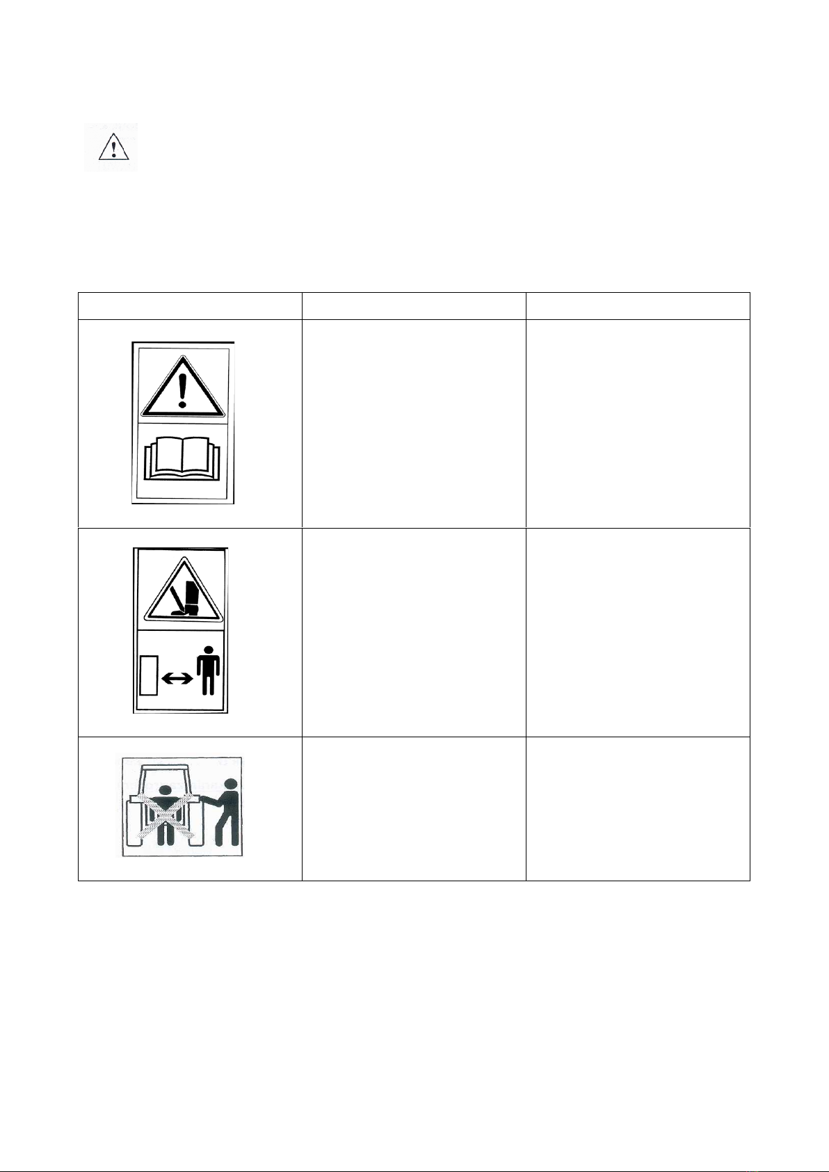
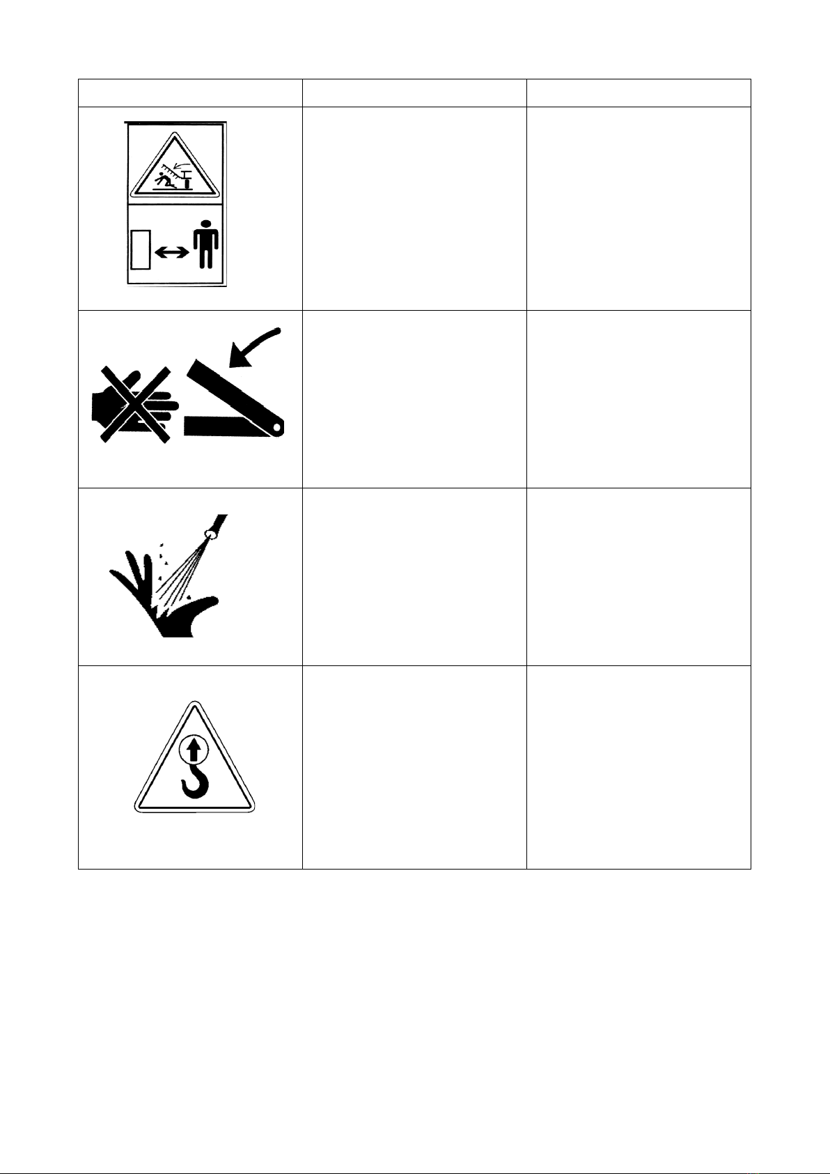
•do not approach the disc harrow while it is being lifted or lowered,
•do not stay between the disc harrow and the tractor when the engine is running,
•drive away with the implement, lift and lower it slowly and smoothly, without
jerking, making sure no outsiders are in the area,
•do not reverse and make U-turns when the implement is lowered to the working
position,
•when making U-turns do not use independent tractor brakes;
•during the operation and travel do not stand on the implement and do not put
additional loads onto it;
•while making U-turns, pay due caution if anyone is in the vicinity,
•never use the disc harrow on slopes with the inclination exceeding 12°,
•any repairs, lubrication or cleaning of working components may be performed as
long as the engine is not running and the implement is lowered and unfolded,

13
•there is a hazard of head injury when you perform maintenance or replacement of
parts in or under the implement without adequate protection – wear a hardhat,
•during a break in the work, always lower the implement to the ground and stop the
tractor engine,
•the harrow with the working width exceeding 3.00 m is equipped with a mechanical
lock which blocks the side extensions from uncontrolled opening during standstill
and road travel,
•driving and parking the implement on an unstable slope may cause soil slipping,
•store the implement in a manner preventing injury to people and animals.
3.1 Hitching and unhitching from a tractor
•Hitch the implement with the tractor according to the recommendations, use pins
and protect the suspension pins with cotter pins.
•When hitching the disc harrow, do not stay between the tractor and the attached
implement.
•The tractor used together with the disc harrow must be fully functional and in good
working order. It is forbidden to couple the machine to any tractor with a
malfunctioning pneumatic system (if the machine has a braked axle) and hydraulic
system.
•Remember to observe the following: balance of the tractor and the suspended
implement, tractor steerability and braking performance – the front axle load must
not drop below 20% of the total tractor load – a kit of front weights;
•When in resting position and disconnected from the tractor, the machine must be
stable all the time.
•Place the support leg on a stable ground. Do not use pads under the leg as this may
cause instability.
3.2 Tyres
•Tyre pressure cannot exceed the value recommended by the manufacturer.
Transporting the implement when the pressure is too low is prohibited. This may
cause damage to the implement or an accident when travelling too fast and on very
uneven surfaces.
•Considerably damaged tyres (particularly the tyre profile) must be replaced
immediately.
•Protect the implement from rolling away when replacing the tyres.
•The repair works on wheels or tyres must be performed by persons trained and
authorised for this purpose. Such works must be performed with properly selected
tools.
•Following every assembly of wheels, check the tightening of nuts after travelling
the distance of 50 km.
3.3 Hydraulic and pneumatic systems
The hydraulic and pneumatic systems are pressurised.
Take all precautionary measures, in particular:
•do not connect and disconnect hydraulic hoses when the tractor hydraulic system is
pressurised (hydraulics set to neutral),

14
•regularly check the hydraulic and pneumatic connections and hoses,
•do not use the implement until the hydraulic or pneumatic system is repaired.
3.4 Transport safety on public roads
For transport, the side sections of the GAL 4.0 H, GAL 5.0 H, GAL 6.0 H disc
harrow should be folded into the transport position by means of a hydraulic system. Before
folding, the machine must be lifted sufficiently high until the folded side sections do not
collide with the ground.
The disc harrow must be protected against unfolding by means of the mechanical lock.
GAL disc harrows equipped with a chassis – the wheels should be lowered to a degree
where the side sections do not interfere with the ground when folded.
While in transport, the clearance under the machine must be at least 30 cm.
While transporting the implement on public roads, it is absolutely mandatory to use lights,
an identification sign and reflective side lights.
Do not exceed the maximum travel speeds:
–up to 20 km/h on smooth (asphalt) roads,
–6-10 km/h on dirt roads or cobblestones,
–up to 5 km/h on bumpy roads.
After folding the machine, slide the rollers together and secure them with bolts in the
ladders in order to achieve a smaller transport width.
Travelling speed must be adapted to the road and the existing conditions so that the disc
harrow cannot jump on the tractor suspension system and excessive loads on the machine
frame and the tractor suspension system can be avoided.
Act with due caution when passing and overtaking or travelling at curves. The maximum
implement width on public roads is 3.0 m.
Do not drive with the implement if the slope is inclined crosswise to the implement by
more than 7°.
WARNING! Any failure to observe the above rules may pose hazard to the
operator and other people. It may also result in damaging the machine. The
user shall be liable for any damage caused by failure to observe the rules!
3.5 Residual risk description
Mandam Sp. z o.o. makes every effort to eliminate the risk of accidents. However,
there is some residual risk that may result in an accident. The biggest hazard occurs
when/during:
•using the implement for purposes other than described in the manual,
•operating the implement by people who are underage and do not have licences, are
ill or intoxicated,
•presence of people and animals within the implement operating range,
•precautionary measures are not taken during transport and maneouvering with the
tractor,
•staying on the implement or between the tractor and the implement when the
engine is running;
•during operation when operation guidelines are not followed,

15
•driving on public roads.
3.6 Residual risk assessment
•The residual risk can be minimised by applying the following recommendations:
•operate the implement carefully and without undue haste,
•read the instruction manual carefully,
•keep a safe distance from hazard zones,
•do not stay on the implement and within the implement operating range when the
engine is running,
•perform the maintenance in accordance with safety rules,
•wear safety clothes and a safety helmet while working under the implement;
•prevent the access of unauthorized personnel and especially children to the
implement.
4Information on operation and use
Before the machine is put into operation for the first time:
•read the instruction manual,
•make sure that the machine is in proper operating condition,
•check the condition of the hydraulic and pneumatic system (replace damaged
components, e.g. pressure hoses),
•make sure that the hydraulic hose quick-connectors of the machine match the
tractor sockets,
•check the tightening of bolts and nuts,
•check if the air pressure in tyres is according to the manufacturer’s
recommendations,
•make sure that all components requiring lubrication are lubricated,
•make that the pressure in the tractor wheels is the same on all axles to ensure
smooth operation.
CAUTION! The permissible loads on the axles and tyre load capacities must
not be exceeded. The front axle load may not be less than 20%.

16
Fig. 2 Diagram of the markings of tractor loads.
Axle load calculations
Key:
GC– tractor weight,
TP – front axle load for the unhitched tractor,
TT – rear axle load if the tractor is empty,
GP – total weight of the front-mounted implement,
GT – total weight of the rear-mounted implement,
a – distance between the centre of gravity of the front-mounted implement and the axle
centre,
b – tractor wheelbase,
c – distance between the rear axle centre and the centre point of the hitching pin of the
rear-mounted implement,
d – distance of the centre of gravity of the agricultural implement from the hitching pins
of the tractor,
x – distance of the centre of gravity from the rear axle (assume 0.45 if the manufacturer
does not provide this parameter).
Minimum load at the front in case of a rear-mounted implement:
Actual load on the front axle:
Actual total weight:

17
Actual load on the rear axle:
4.1 Preparation of the disc harrow
The disc harrow is usually supplied for sale in a ready-to-operate condition. Due to
the limitations of the means of transport, it is also possible to deliver it in a partially
disassembled condition – usually by disconnecting the roller.
When preparing the unit for operation for the first time, its components (roller)
must be assembled. To this end, place the disc harrow on a flat hard surface in a position
where the roller can be manoeuvred. A lifting device with a load capacity of at least 500
kg in (700 kg in the case of a rubber roller) must be used for transporting the roller to
ensure stability during transport. Position the arms in the harrow holders and connect the
arms to the roller clamp using screws (Fig. 5).
Fig. 5 Arm and roller clamp connection.
Prior to operation check the technical condition of the disc harrow, in particular that of
the working parts and screw connections.
CAUTION! The correct procedure for mounting the rollers in the arm
clamps requires that the screws are tightened evenly diagonally so that
the entire plane of the arm brackets is flush with the plane of the roller
clamp profile. This provides the most secure way of connecting the roller
arms to the machine!
4.2 Hitching the disc harrow with the tractor

18
Tyre pressure in the tractor wheels must comply with the values recommended by
the manufacturer. The lower bars of the three-point hitch should be at the same height,
spaced correspondingly to the spacing of the lower points of hitch. While attaching the
disc harrow to the tractor, the harrow must be placed on hard and even ground.
Fig. 6 Three-point hitch of the tractor: 1,2 – lower bars, 3 – upper fastener, 4 – left support rail, 5 – right
support rail with adjustable length, 6 – lift arm, 7 – lift shaft.
While attaching the disc harrow to the tractor, complete the following steps:
•switch the tractor hydraulic system into adjustment position,
•uncouple the suspension axle from the implement and attach it to the tractor’s
lower bars,
•reverse the tractor to a distance that allows the suspension axle to be connected
to the frame plates and the upper fastener and harrow support rail,
•secure the suspension axle in the frame plates using the clamps and pins,
•attach the tractor’s upper fastener. During operation of the implement, the hitch
point of the upper fastener at the implement must be located higher than the
attachment point of this fastener at the tractor,
•check the lifting and lowering of the implement.
Each tractor connected to the machine must be equipped with a set of weights and
maintain control during transport, i.e. a minimum of 20% of the tractor’s weight
must be transmitted to the front axle of the tractor.
4.3 Hitching the sower with the disc harrow
Before attaching the sower, check the weight of the sower and the seed. The load
capacity of the hydropack is 1,300 kg. When coupling the sower with the disc harrow,
proceed as follows:
•adjust the distance between the hooks to the distance between the sower hitching
pins by placing the hook on the proper side of the arm and putting the spacer,
•lower the lower bars of the coupling below the sower hitching pins (in case of the
coupling on a chassis, insert the pin into the corresponding hole in the support rails
of the bar, then adjust the position using the cylinder),
•reverse the set to bring the sower pins into the hooks,

19
•place the protection cover on the pins and the hook hole and secure with a pin,
•connect the upper fastener with the sower.
CAUTION! Before lifting the disc harrow, the sower must be lifted to ensure
the stability of the implement.
4.4 Operation and adjustment
4.4.1 Automatic locking of the machine side extensions
On machines with folding sections, an automatic lock is available that requires no
additional operation. The lock uses a mechanism consisting of a cylinder and a hook
(Fig. 7).
Fig. 7 Main frame with automatic side extension locking mechanism.
4.4.2 Implement opening sequence
Before unfolding the folding side the extensions of the machine, learn the opening
sequence to perform this operation correctly.
1. First, raise the implement as much as possible to be able to fold it correctly,
avoiding the risk of the folding arms snagging on the ground during movement
(Fig. 8).
2. Next, fold the implement side extensions hydraulically into the “closed” position
to ensure that the side extension lock mechanism will unlock and allow the
implement arms to be opened at a later stage. This operation is necessary each
time the arms are opened (Fig. 8).

20
Fig. 8 Implement opening sequence: 1- raise the implement up to the maximum, 2- fold the side
extensions into the “closed” position.
3. Then, after making sure that the hook of the hydraulic side extension lock
mechanism allows the machine side extensions to be unlocked, proceed to open
them fully (Fig. 9).
Fig. 9 Implement opening sequence: 3- release the hook of the hydraulic side extension lock mechanism,
4- open the implement side extensions.
4. When opening the implement’s side extension arms, make sure that the ends of
the arms are at the correct height to prevent them from snagging on the ground
(Fig. 10).
This manual suits for next models
2
Table of contents
Other Mandam Farm Equipment manuals

Mandam
Mandam MWC Series User manual

Mandam
Mandam SPEC HD 2,5 User manual

Mandam
Mandam MGP Series User manual

Mandam
Mandam GAL-K User manual

Mandam
Mandam BTH-D User manual

Mandam
Mandam ORKAN VARIO Series User manual

Mandam
Mandam SUPER User manual

Mandam
Mandam MCH Series User manual

Mandam
Mandam SAL DISC HARROW User manual

Mandam
Mandam Hybro 3,0 User manual