manuals.online logo
Brands
  1. Home
  2. •
  3. Brands
  4. •
  5. Master
  6. •
  7. Engine
  8. •
  9. Master STAR Manual

Master STAR Manual

R
instruction guide STAR / VENUS rev01 16.04.12
Instruction guide for tubular motors with radio electronic limit switch.
X
X
X
VENUS
(Ø 50 mm)
STAR
(Ø 40 mm)
433,92 MHz
www.mastermotion.eu
GUIDANCE
SECURITY
Dear customer, thank you for purchasing a MASTER product.
This leaflet contains important information regarding the methods of use and the safety of installation.
The tubular motor with radio electronic limit switch STAR and VENUS series are suitable to command awnings,
roller shutters and similar. Any other use is improper and forbidden and it could void the manufacturer’s warranty. The technical characteristics are
provided on the label attached on motors. These devices have not been studied to a continuous working.
Comply with the following information and
keep them for future reference.
FOR A CORRECT INSTALLATION, IT IS ADVISABLE TO READ THIS GUIDE.
The manufacturer cannot be considered responsible for any damages, wrong or unreasonable use.
Environmental conservation !
Environmental conservation is an everyone’s duty !
MASTER uses packaging recyclable materials. Dispose materials on the proper containers, complying with the law in force in your locality.
If you are an installer and you use many motors, please ask for cavaties box packaging to your retailer or to the manufacturer, this is an
environmental respectful choice, that limits waste and considerably reduce the packaging materials.
This product may have substances that are polluting for the environment and dangerous for the health.
At the end of the product life cycle, carefully comply with the waste disposal rules. It is strickly forbidden to dispose the product on the domestic
waste.
01.
02.
03.
04.
05.
06.
07.
Warning for the installation.
Important note on radio system.
Offset adapters installation on awnings and roller shutters.
Electrical connection.
Technical dimensions.
Limit switches memorization mode using the command buttons.
.
Memorization of the first trasnmitter when the limit switches have been set using a manual command.
Memorization of an additional transmitter.
Setting of the intermediate position using the command buttons.
Recalling the intermediate position using the command buttons.
Setting of the intermediate position using the transmitter.
Recalling the intermediate position using the transmitter.
Setting again the limit switches.
Deletion of all the transmitters in memory.
Restore the factory settings - RESET.
Memorization/deletion of wind or sun-wind sensor ( ).
Memorization/deletion of a rain sensor ( ).
Other functions.
08.
09.
10.
11.
12.
13.
14.
15.
16.
17.
18.
19.
MISTRAL RADIO, MISTRALBATTERY - ECLIPSE RADIO, ECLIPSE BATTERY
PS12-TX
Limit switches memorization mode using the portable transmitter
01.
25.
26.
The product must be installed by qualified technical personnel so as to comply with the standards and laws in force in your locality.
Check that the package is intact and has not suffered damages in transit.
The motor is connected to dangerous electrical voltage.
Always connect the ground wire (yellow/green) and respect phase (L)and neutral (N) of the power supply.
Command buttons are connected to the main voltage, so they must be properly insulated and protected.
The installer is obliged to fit an isolation device (with 3 mm minimum opening on the contacts) upstream of the system.
Do not modify or replace parts without the manufacturer’s permission.
If the installation is on roller shutter or similar, check that there is no friction for the correct movement.
If there are several radio motors in the same system, the minimum distance between them must not be less than 1,5 metres.
Do not install the device near metal surfaces.
The motor must be of sufficient power for the applied load.
Use 10/10 thick winding rollers.
Check that adapters are of suitable shape and size for the winding roller.
Adapters and supports for the motor must be chosen among the current MASTER catalogue.
Aviolent shock and the use of unsuitable tools can cause the brackage of internal or external part of the motor.
It is forbidden to drill or tamper the motor.
Do not handle motor by the cable.
Any screws used for completing the installation must not touch the motor.
The power supply cable must not touch the moving parts.
The motor is provided with an internal self-resetting thermal safety device, that stops the motor if it overheats.
The motor starts its normal operation when the temperature lowers under the safety limit (usually around 10 or 20 minutes).
The motor must be installed in such a way that it cannot come into contact with liquids.
It is forbidden and dangerous to cut the antenna wire.
For your safety, it is forbidden to work near the winding roller when the motor is being supplied with power.
Warning, after a brief working period the motor overheats, act cautiously.
There must be 1-2 mm of right/left play on the winding roller.
In case of malfunctioning do not keep on trying on the command, but call a qualified technical personnel.
02.
03. Carry out the connections with the power supply disconnected.
04.
05.
06.
07.
08.
09.
10.
11.
12.
13.
14.
15.
16.
17.
18.
19.
20.
21.
22.
23.
24.
It is advisable (for example, near police stations, airports, ports, hospital, etc.). A
technical inspection is in any case advisable before installing any radio system in order to identify sources of interference.
Radio systems can be used where possible disturbances or malfunctioning of the transmitter or the receiver do not cause a risk factor, or if the risk
factor is cancelled by suitable safety systems.
The presence of radio device operating on the same transmission frequency ( ) can interfere with the radio receiver of the motor and so
reduce the range of the system and limit the functionality of the installation.
to avoid using radio systems in areas with strong interference
433,92 MHz
Warning
Table of contents.
01. Warning for the installation.
02. Important note on radio system.
instruction guide STAR / VENUS rev01 16.04.12
FRONT VIEW
MOTOR TO THE LEFT
ADC.670.OGI.DX ADC.678.OGI.DX
BACK VIEW
MOTOR TO THE LEFT
ADC.140.OTT ADC.160.OTT ADC.170.OTT
BACK VIEW
MOTOR TO THE RIGHT
ADC.140.OTT ADC.160.OTT ADC.170.OTT
ADC.670.OGI.SX ADC.678.OGI.SX
FRONT VIEW
MOTOR TO THE RIGHT
THE DOWNWARD MOVEMENT OBSTACLE DETECTION (ROLLER SHUTTER) OR SELF-LIMIT SWITCHES SETTING
(AWNING)FUNCTIONS ONLY USING OFFSET ADAPTER SERIES,
CORRECTLY INSTALLED AS SHOWN IN THE PICTURES.
ARE GUARANTEED
L
N
motor cable
grey
brown
blue
yellow/green
black
manual command
(optional)
stricktly
spring return
type
MAIN POWER
SUPPLY
8
2000
Depth
max. 9
30
50
13 42
Ø 12
11
6
14
Depth
max. M4x10
27
63
13
10
10
53
14
9
16
mod. STAR mod. VENUS
03. Offset adapters installation on awnings and roller shutters.
04. Electrical connection.
Ground
Neutral
Phase
Manual
command
05. Technical dimensions.
dimensions in «mm»
dimensions in «mm» dimensions in «mm»
Motor cable length
instruction guide STAR / VENUS rev01 16.04.12
ON
SWITCH ON
POWER SUPPLY
BRING THE MOTOR
TO THE INTERMEDIATE
POSITION
(around half way)
IDENTIFY THE BUTTON
THAT MOVES THE
MOTOR DOWNWARD
WAIT THE
AUTOMATIC
STOP
(
).
anyway it is possible
to modify the limit switch
position using
the manual command
ROLLER SHUTTER
WITH STOPPERS
AFTER 2 SECONDS
THE MOTOR OPERATES
A LARGE DOWNWARD
MOVEMENT AND TWO
SMALL UPWARD
MOVEMENTS.
ROLLER SHUTTER
WITHOUT STOPPERS
AUTOMATIC
STOP
WITHIN 8 SECONDS
PRESS « »
ON THE TRANSMITTER
TO BE STORED.
STOP
THE UPWARD MOVE
OF THE MOTOR
SIGNALS THE
STORAGE.
MANUAL STOP
WAIT THE AUTOMATIC STOP
(
).
anyway it is possible to modify the limit switch
position using the manual command
CASSETTE
AWNING
SQUARE BAR
AWNING
AUTOMATIC
STOP
MANUAL STOP
AFTER 2 SECONDS THE MOTOR OPERATES
A LARGE DOWNWARD MOVEMENT AND TWO
SMALL UPWARD MOVEMENTS.
WITHIN 8 SECONDS
PRESS « »
ON THE TRANSMITTER
TO BE STORED.
STOP
THE UPWARD MOVE
OF THE MOTOR
SIGNALS THE
STORAGE.
MANUAL STOP
(
).
anyway it is possible
to modify the limit switch
position using
the manual command
THE SCREEN
NEEDS
BECAUSE ITS
UPPER POSITION IS
NOT DELIMITED
BY AN OBSTACLE.
THE MANUAL
STOP
THE UPWARD MOVE
OF THE MOTOR
SIGNALS THE
STORAGE.
WITHIN 8 SECONDS
PRESS « »
ON THE TRANSMITTER
TO BE STORED.
STOP
WAIT THE
AUTOMATIC STOP
(
).
anyway it is possible
to modify the limit switch
position using
the manual command
AUTOMATIC
STOP
WITHIN 8 SECONDS
PRESS « »
ON THE TRANSMITTER
TO BE STORED.
STOP
THE UPWARD MOVE
OF THE MOTOR
SIGNALS THE
STORAGE.
06. Limit switches regulation mode using the command buttons.
After the sequence of press, the motor sets up for the chosen application. It could happen that the down button commands an upward move and vice-versa.
This behaviour forms an integral part of the procedure.
PRESS
3 TIMES
DOWN
PRESS
5 TIMES
DOWN
PRESS
7 TIMES
DOWN
PRESS
9 TIMES
DOWN
THEN PRESS AND RELEASE IN QUICK SUCCESSION
THE BUTTON THAT MOVES THE MOTOR DOWNWARD IF THE APPLICATION IS FOR :
(without moving the motor, 1 sec. between one press and the next)
RULLER SHUTTER AWNING SCREEN GARDEN
Offset adapter necessary Offset adapter advised Standard adapter Offset adapter necessary
WAIT AROUND
8 SECONDS
THE MOTOR MOVES
UPWARD.
WAIT AROUND 8 SECONDS
THE MOTOR MOVES UPWARD.
WAIT AROUND
8 SECONDS
THE MOTOR MOVES
UPWARD.
WAIT AROUND
8 SECONDS
THE MOTOR MOVES
UPWARD.
WAIT AROUND
2 SECONDS.
THE MOTOR MOVES
DOWNWARD.
WAIT AROUND 2 SECONDS,
THE MOTOR MOVES DOWNWARD.
WAIT AROUND
2 SECONDS.
THE MOTOR MOVES
DOWNWARD.
WAIT AROUND
2 SECONDS.
THE MOTOR MOVES
DOWNWARD.
AFTER 2 SECONDS THE MOTOR OPERATES
A LARGE DOWNWARD MOVEMENT AND TWO
SMALL UPWARD MOVEMENTS. AFTER 2 SECONDS THE
MOTOR OPERATES
A LARGE DOWNWARD
MOVEMENT AND TWO
SMALL UPWARD
MOVEMENTS.
instruction guide STAR / VENUS rev01 16.04.12
ON
SWITCH ON
POWER SUPPLY
PRESS
«»PROG
IF PRESSING THE BUTTON UP ON THE TRANSMITTER
THE MOTOR MOVES DOWNWARD
PRESS AGAIN «
ON THE TRANSMITTER.
AUTOMATICALLY UP BUTTON
ON THE TRANSMITTER CORRESPONDS TO
THE UPWARD MOVE OF THE MOTOR.
PROG» PRESS AGAIN
«»PROG
UP
PRESS
9 TIMES
«STOP»
WAIT THE
AUTOMATIC
STOP
(
).
anyway it is possible
to modify the limit switch
position using
the tranmsitter
WAIT THE AUTOMATIC STOP
(
).
anyway it is possible to modify the limit switch
position using the tranmsitter
MANUAL STOP
.
(
)
anyway it is possible
to modify the limit switch
position using
the tranmsitter
WAIT THE
AUTOMATIC STOP
(
).
anyway it is possible
to modify the limit switch
position using
the transmitter
ROLLER SHUTTER
WITH STOPPERS
ROLLER SHUTTER
WITHOUT STOPPERS
AUTOMATIC
STOP
MANUAL STOP
CASSETTE
AWNING
SQUARE BAR
AWNING
AUTOMATIC
STOP
MANUAL STOP
MANUAL STOP.
WITHIN
8 sec.
07. Limit switches regulation mode using the portable transmitter.
If the procedure is stopped for switching off of power, it must be completely repeated. If during the procedure some forbidden opearation are performed, the motor
signals the anomaly operating an upward movement and a downward movement for 3 times. In this case switch off power and repeat the procedure.
AUTOMATIC
STOP
WAIT
2 sec.
WAIT
2 sec.
WAIT
2 sec.
WAIT
2 sec.
THEN PRESS AND RELEASE IN QUICK SUCCESSION (without moving the motor, 1 sec. between one press and the next)
THE BUTTON «STOP» IF THE APPLICATION IS :
PRESS
7 TIMES
«STOP»
PRESS
5 TIMES
«STOP»
PRESS
3 TIMES
«STOP»
ROLLER SHUTTER AWNING SCREEN GARDEN
Offset adapter necessary Offset adapter advised Standard adapter Offset adapter necessary
WAIT AROUND
2 SECONDS.
THE MOTOR MOVES
DOWNWARD.
WAIT AROUND 2 SECONDS,
THE MOTOR MOVES DOWNWARD.
WAIT AROUND
2 SECONDS.
THE MOTOR MOVES
DOWNWARD.
WAIT AROUND
2 SECONDS.
THE MOTOR MOVES
DOWNWARD.
WAIT AROUND
8 SECONDS
THE MOTOR MOVES
UPWARD.
WAIT AROUND 8 SECONDS
THE MOTOR MOVES UPWARD.
WAIT AROUND
8 SECONDS
THE MOTOR MOVES
UPWARD.
WAIT AROUND
8 SECONDS
THE MOTOR MOVES
UPWARD.
instruction guide STAR / VENUS rev01 16.04.12
USING THE MANUAL COMMAND,
BRING THE MOTOR TO THE
LOW LIMIT POSITION.
OFF
SWITCH OFF
POWER SUPPLY
ON
SWITCH ON
POWER SUPPLY
WAIT
2 sec.
WITHIN
8 sec.
WAIT
2 sec.
PRESS
IN QUICK SUCCESSION
THE BUTTON
10 TIMES
DOWN
PRESS
IN QUICK SUCCESSION
THE BUTTON
2 TIMES
DOWN
x 10 TIMES
DOWN
x 2 TIMES
DOWN
PERFORM THE OPERATION WITHIN: 15 seconds
THE MOTOR OPERATES 2 SMALL
UPWARD MOVEMENTS
TO SIGNAL THE ENTRY INTO
THE TRANSMITTER MENU
PRESS
BUTTON « »
ON THE TRANSMITTER
TO BE STORED IN MEMORY
STOP
THE UPWARD MOVEMENT OF THE
MOTOR SIGNALS
THE STORAGE.
USING THE
TRANSMITTER ALREADY
IN MEMORY BRING
THE MOTOR TO THE
INTERMEDIATE POSITION.
PRESS AND HOLD
« » ON THE
TRANSMITTER ALREADY
IN MEMORY
PROG PRESS «STOP» ON
THE NEW TRANSMITTER
TO BE STORED IN MEMORY
THE MOTOR
OPERATES
2 UPWARD
MOVEMENTS
WITHIN
8 sec.
THE UPWARD MOVE
OF THE MOTOR SIGNALS
THE STORAGE.
INTERMEDIATE
POSITION
(around half way).
THE MOTOR STARTS TO MOVE
AND STOP IN THE INTERMEDIATE
POSITION PREVIOUSLY
STORED.
WAIT
2 sec.
TO SET
THE INTERMEDIATE POSITION
PRESS AND
(holding STOP)
PRESS
STOP
UP
PRESS AND HOLD
STOP + UP
BRING THE MOTOR
TO THE DESIRED
INTERMEDIATE
POSITION
THE MOTOR STORES
THE INTERMEDIATE POSITION
AND COMMANDS 2 MOVEMENTS
ON THE OPPOSITE DIRECTIONS.
WAIT
2 sec.
08. Memorization of the first trasnmitter when the limit switches have been set using a manual command.
09. Memorization of an additional transmitter.
10. Setting the intermediate position using the command buttons.
11. Recalling the intermediate position using the command buttons.
12. Setting the intermediate position using the transmitter.
TO SET THE INTERMEDIATE
POSITION PRESS
IN QUICK
SUCCESSION THE
BUTTON
5 TIMES
UP
x 5 TIMES
UP
USING THE
MANUAL COMMAND
BRING THE MOTOR
ON THE DESIRED
INTERMEDIATE POSITION THE MOTOR STORES
THE INTERMEDIATE POSITION
AND COMMANDS 2 MOVEMENTS
ON THE OPPOSITE DIRECTIONS.
WAIT
2 sec.
instruction guide STAR / VENUS rev01 16.04.12
THE MOTOR STARTS TO MOVE
AND STOP IN THE INTERMEDIATE
POSITION PREVIOUSLY
STORED.
WAIT
2 sec.
WAIT
2 sec.
TO RECALL
THE INTERMEDIATE POSITION
PRESS AND
(holding STOP)
PRESS
STOP
DOWN
OFF
SWITCH OFF
POWER SUPPLY
ON
SWITCH ON
POWER SUPPLY
WAIT
2 sec.
PRESS THE SEQUENCE
STOP PROG STOP
WITHIN
8 sec.
WITHIN
8 sec.
THE MOTOR MOVES
DOWNWARD.
NOW FOLLOW THE
PREVIOUS POINTS 06-07
«LIMIT SWITCHES MEMORIZATION»
OFF
SWITCH OFF
POWER SUPPLY
ON
SWITCH ON
POWER SUPPLY
WAIT
30 sec.
CONNECT
TOGETHER
BLACK +
GREY +
BROWN
OFF
SWITCH OFF
POWER SUPPLY
RESTORE THE
CONNECTIONS
ON
SWITCH ON
POWER SUPPLY
THE MOTOR MOVES
2 TIMES ON THE
OPPOSITE DIRECTIONS
IF YOU WANT TO
STORE AGAIN A
TRANSMITTER
FOLLOW THE
PROCEDURE 08.
OFF
SWITCH OFF
POWER SUPPLY
ON
SWITCH ON
POWER SUPPLY
CONNECT
TOGETHER
BLACK +
GREY +
BROWN
OFF
SWITCH OFF
POWER SUPPLY
RESTORE THE
CONNECTIONS
ON
SWITCH ON
POWER SUPPLY
WAIT
30 sec.
TRANSMITTERS
DELETION
WAIT
15 sec.
LIMIT SWITCHES
DELETION
NOW FOLLOW THE
PREVIOUS POINTS 06-07
«LIMIT SWITCHES MEMORIZATION»
WAIT
2 sec.
USING A TRANSMITTER
ALREADY IN MEMORY BRING THE
MOTOR TO THE INTERMEDIATE POSITION.
INTERMEDIATE
POSITION
(around half way).
PRESS AND HOLD « » ON THE
TRANSMITTER UNTIL THE MOTOR
OPERATES 2 UPWARD MOVEMENTS
PROG
1
TO
STORE
TO
DELETE
«1»
PRESS
BUTTON
ON THE SENSOR
«1»
PRESS
BUTTON
ON THE SENSOR
ACTIVATION/DEACTIVATION PROCEDURE FOR THE «SUN FUNCTION» (only if ECLIPSE RADIO or ECLIPSE BATTERY are stored) IS DIFFERENT ACCORDING
TO THE USED TRANMSITTER. IT IS ADVISABLE TO SEE THE INSTRUCTION MANUAL OF THE TRANSMITTER.
13. Recalling the intermediate position using the transmitter.
14. Setting again the limit switches.
15. Cancellation of all the transmitters in memory.
16. Restore the factory settings - RESET.
17. Memorization or deletion of a wind or sun-wind sensor ( ).MISTRAL RADIO, MISTRAL BATTERY - ECLIPSE RADIO, ECLIPSE BATTERY
For MISTRAL BATTERY and ECLIPSE BATTERY hold
button 1 for around 3 seconds, until the motor moves.
PRESS AND HOLD
STOP + DOWN
instruction guide STAR / VENUS rev01 16.04.12
«P2»
PRESS
BUTTON
ON THE SENSOR
«P2»
PRESS
BUTTON
ON THE SENSOR
P2
PS12-TX
60.000.016
WITHIN
8 sec.
TO
STORE
TO
DELETE
14
18. Memorization/deletion of a rain sensor (PS12-TX).
19. Other functions.
19.1 ROD «Rise Obstacle Detection» function - not available for screen type application
During the upward movement, the motor activates the ROD function to detect the presence of obstacles that will prevent the normal movement of the motor. If an obstacle is detected, the
upward movement is stopped and a small downward movement is operated to free the structure of the traction due to the presence of the obstacle. During this small automatic downward
movement all the manual controls are inhibited.
19.2 STS «Soft Touch System» torque control - not available for screen type application
Near the upper limit switch, the STS torque control limits the motor torque and adapts it to the weight of the roller shutter/awning to guarantee a soft lean with the obstacle that delimits the
upper limit switch.
19.3 Control on the safety catches SHD «Safety Hook Detection» - available for roller shutter application only
If the roller shutter has safety catches, the SHD function detects the presence of the safety catches, and if they are present it stops the upward movement and operates the closing of the
roller shutter without damaging it.
19.4 FOD «Fail Obstacle Detection» function - not available for screen type application
The correct operation of the downward movement obstacle detection function depends on the use of the offset adapter and its correct installation, in accordance with what is illustrated in the
previous pictures. During the downward movement, the motor activates the FOD function to detect the presence of obstacles that will prevent the normal movement of the motor. If an
obstacle is detected, the downward movement is stopped and a large upward movement is operated to allow the obstacle to be removed. During this upward movement, all the control
buttons are inhibited.
In the roller shutter or awning type installations the FOD function is normally active. In situation where the downward movement obstacle detection is not working correctly due to the
presence of structural friction that affects the natural sliding of the roller shutter or awning, it is possible to deactivate the FOD function.
Bring the motor to the intermediate position (around half way)
Press and hold of a transmitter already stored in memory for about 4 seconds, until the motor operates 2 upward movements.
B ress again . The motor operates 3 upward movements to signal the «FOD programming».
Press . The motor displays the current setting. 1 upward movement = function is ACTIVE, while 1 downward movement =function is INACTIVE.
If you want to modify the setting press . The motor displays the new setting and then returns to its normal activity.
If the setting is already the one you want, wait without carrying out any operation. After about 8 seconds the motor operates 2 downward movemetns to signal that the setting has been
modified.
To ACTIVATE/DEACTIVATE the FOD function follow this procedure:
1.
2. PROG
3. PROG
4. STOP
5. STOP
6.
riefly p entry into
19.5 Radio test function
This type of motors is able to manage information received from a radio sensor (MISTRAL RADIO, MISTRAL BATTERY, ECLIPSE RADIO, ECLIPSE BATTERY, PS12-TX). If a radio sensor
of this type is stored in the memory of the motor, a communication test is automatically activated between sensor and motor. If the communication is absent (due to failure of one or both the
devices or due to interference), the device commands an upward movement.
This movement is operated periodically (about every 20 minutes) until radio communication is restored.
To ACTIVATE / DEACTIVATE the RADIO TEST setting using a transmitter already stored in memory follow this procedure:
1. Bring the motor to the intermediate position (around half way)
Press and hold button of the transmitter already stored in memory for about 4 seconds, until the motor operates 2 upward movements.
Briefly press again . The motor operates 3 upward movements to signal the entry into «FOD programming».
Briefly press . The motor operates 4 upward movements to signal «RADIO TEST programming».
Briefly press . The motor displays the current setting. 1 upward movement = RADIO TEST ACTIVE, while 1 downward movement = RADIO TEST INACTIVE
If you want to modify the setting, press . The motor displays the new setting and returns to its normal activity.
If the setting is already the one you want, wait without carrying out any operation. After about 8 seconds the motor operates 2 downward movements to signal that the current setting has
not been modified.
2. PROG
3. PROG
4. PROG
5. STOP
6. STOP
7.
19.5 Movement operated by TIMERS
This type of motor is able to receive commands from transmitters equipped with timers, such as for example, VECTOR 24. For further information regarding the control of the motor through
timers, please contact your delear or consult the transmitter instruction manual.
19.6 Wake-up function
This function is available only if a transmitter code VECTOR 24 is stored in the memory of the motor. If a timer with transmission code F1 is set on the transmitter, on receiving the code, the
motor operates a short upward movement; after an interval of about 2 minutes, another short upward movement is operated and so on, so as to illuminate the room gradually.
Any manual (coming from control buttons or portable tranmitter) or automatic (coming from timers or radio sensors) command stops the procedure.
For any further information on the setting procedure, please refer to the transmitter VECTOR 24 instruction manual.
19.7 Self-calibration of the limit switches
If the upper limit switch has been learnt by the motor by collision with an obstacle (case of roller shutter with stoppers) the motor avoids continually colliding with the stop by stopping a few
seconds earlier. If the control electronics consider it advisable, it is possible that the roller shutter will occasionally lean with the upper stop and a limit switches calibration operation will be
carried out. The impact will in any case be soft since it is managed by the STS torque control. During the calibration operation, some small movements might be carried out during which the
manual controls are inhibited.
19.8 Compatible tranmsitters
These motors are compatible with all the transmitter series OTELLO, VECTOR, WALL and TX3 EGO and are able to store up to 40 different radio codes, one of which can be the one of a
radio sensor.
USING THE TRANMSITTER
ALREADY IN MEMORY BRING THE MOTOR
TO THE INTERMEDIATE POSITION.
INTERMEDIATE
POSITION
(around half way).
PRESS AND HOLD « » ON THE
TRANSMITTER UNTIL THE MOTOR
OPERATES 2 UPWARD MOVEMENTS
PROG
All products and technical characteristics on this document are subjects to variations without any notice.
MASTER declares that the device meets the principal requirements and the other regulations of the directive 1999/5/CE.
The declaration of conformity of the above products is available on the web site ,section «Conformity products».http://www.mastermotion.eu/it-IT/download instruction guide STAR / VENUS rev01 16.04.12
This manual suits for next models

1

Other Master Engine manuals

Master LINE User manual

Master

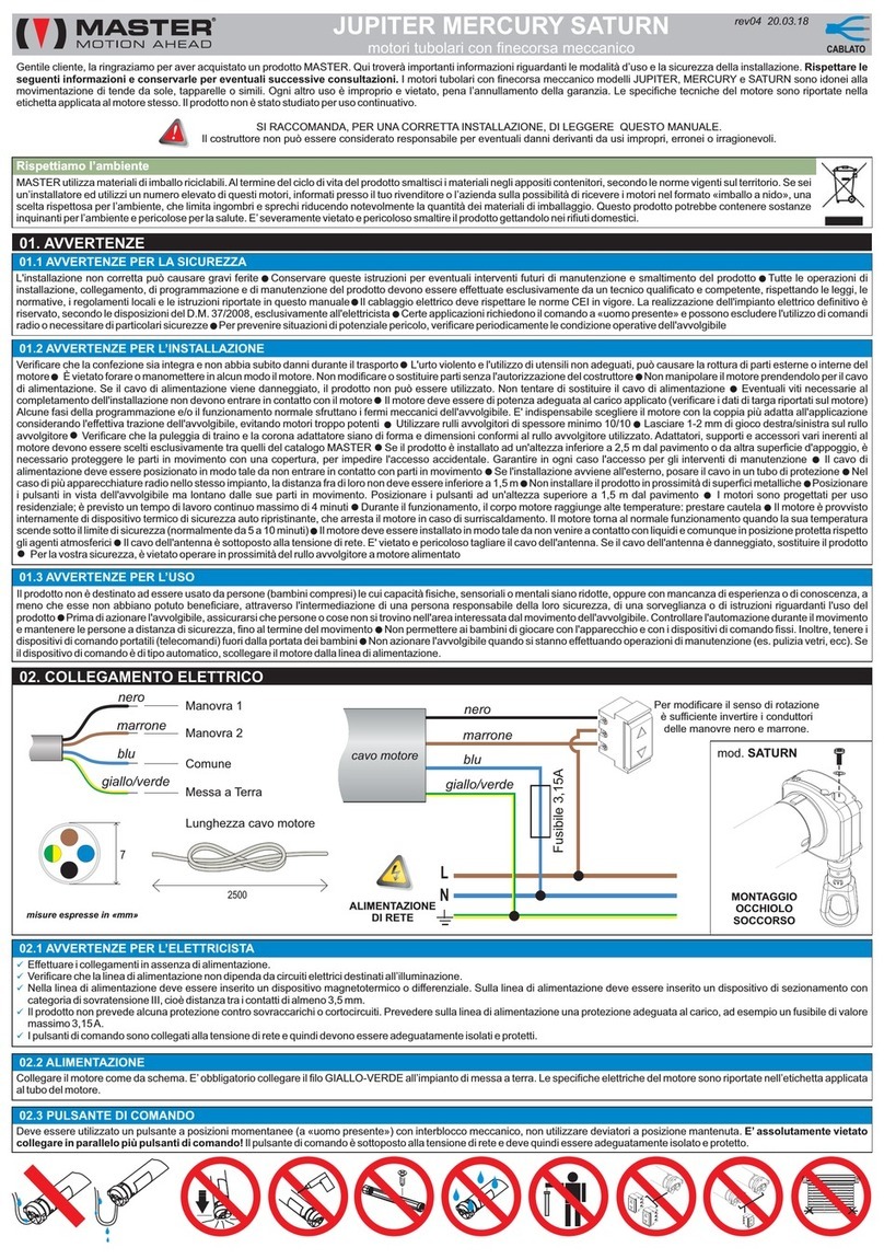
Master LINE User manual

Master JUPITER User manual

Master

Master JUPITER User manual

Master UNCO User manual

Master

Master UNCO User manual

Master MOON Series User manual

Master

Master MOON Series User manual

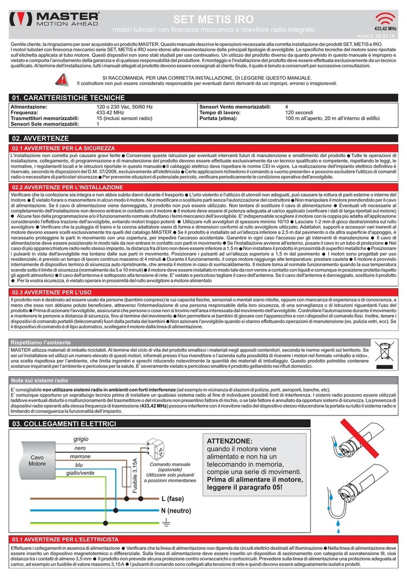
Master SET User manual

Master

Master SET User manual

Master MODO User manual

Master

Master MODO User manual

Master STONE User manual

Master

Master STONE User manual

Master WIND-P Manual

Master

Master WIND-P Manual

Master RIO User manual

Master

Master RIO User manual

Master Master Jump JL290406 User manual

Master

Master Master Jump JL290406 User manual

Master Double 100 User manual

Master

Master Double 100 User manual

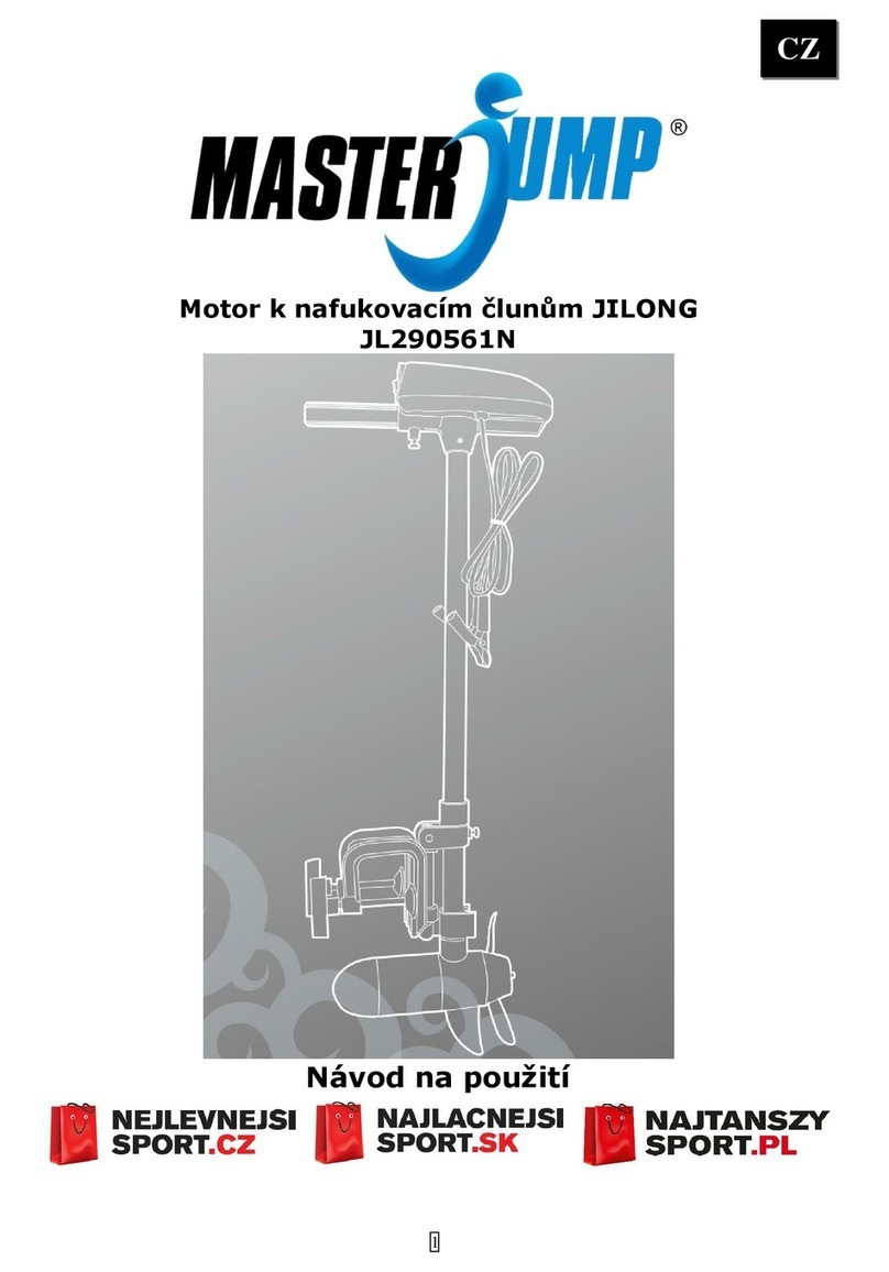
Master Master Jump JL290561N User manual

Master

Master Master Jump JL290561N User manual

Master TOOL User manual

Master

Master TOOL User manual

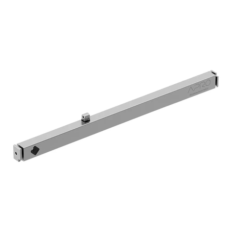
Master Apro User manual

Master

Master Apro User manual

Master GEO-SIDE User manual

Master

Master GEO-SIDE User manual

Popular Engine manuals by other brands

Fuzion 116195 Instruction

Fuzion

Fuzion 116195 Instruction

Tecumseh OHV140 Operator's manual

Tecumseh

Tecumseh OHV140 Operator's manual

O.S. engine FS-30S Owner's instruction manual

O.S. engine

O.S. engine FS-30S Owner's instruction manual

Atlas Copco LZB33-LB-AR009-11 Product instructions

Atlas Copco

Atlas Copco LZB33-LB-AR009-11 Product instructions

Nice Era Quick Series Instructions and warnings for installation and use

Nice

Nice Era Quick Series Instructions and warnings for installation and use

Briggs & Stratton Intek 110600 Operation and owner's manual

Briggs & Stratton

Briggs & Stratton Intek 110600 Operation and owner's manual

GOSS Power Products AP156F operating instructions

GOSS Power Products

GOSS Power Products AP156F operating instructions

VM Motori MR704LX instruction manual

VM Motori

VM Motori MR704LX instruction manual

VM Motori D703E2 instruction manual

VM Motori

VM Motori D703E2 instruction manual

Ebmpapst M3G084-DF18-81 operating instructions

Ebmpapst

Ebmpapst M3G084-DF18-81 operating instructions

MOOG ANIMATICS SMARTMOTOR COMBITRONIC Installation and startup

MOOG ANIMATICS

MOOG ANIMATICS SMARTMOTOR COMBITRONIC Installation and startup

SOMFY LV25 installation guide

SOMFY

SOMFY LV25 installation guide

KaVo EWL 4029 operating instructions

KaVo

KaVo EWL 4029 operating instructions

WilTec XPOTool GK420 Operation manual

WilTec

WilTec XPOTool GK420 Operation manual

Zenoah G430RC owner's manual

Zenoah

Zenoah G430RC owner's manual

GRAUPNER Nitro Bull 28 instruction manual

GRAUPNER

GRAUPNER Nitro Bull 28 instruction manual

Mile HaoXianG Model Technology DLE-55 user manual

Mile HaoXianG Model Technology

Mile HaoXianG Model Technology DLE-55 user manual

THUNDER TIGER PRO Series instructions

THUNDER TIGER

THUNDER TIGER PRO Series instructions

manuals.online logo
manuals.online logoBrands
  • About & Mission
  • Contact us
  • Privacy Policy
  • Terms and Conditions

Copyright 2025 Manuals.Online. All Rights Reserved.