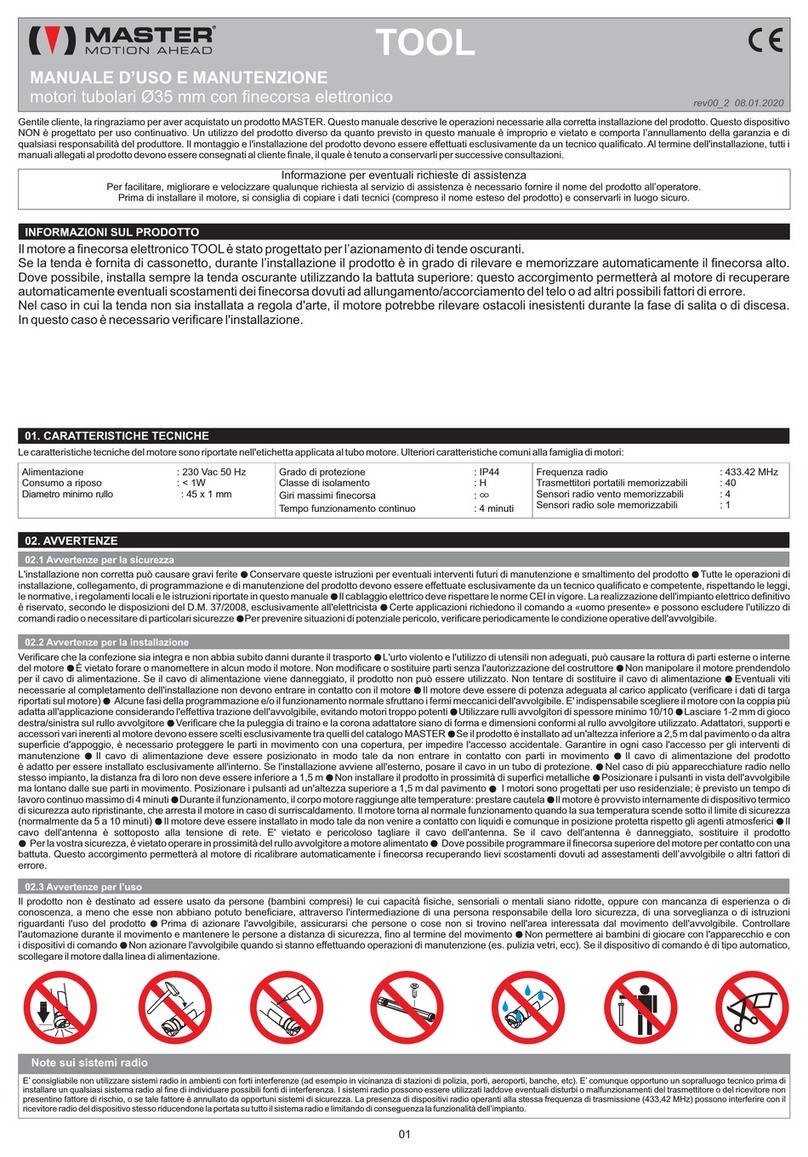
Master STONE User manual

Gentile cliente, la ringraziamo per aver acquistato un prodotto MASTER. Questo manuale descrive le operazioni necessarie alla corretta installazione del prodotto. Questo
dispositivo NON è progettato per uso continuativo. Un utilizzo del prodotto diverso da quanto previsto in questo manuale è improprio e vietato e comporta l’annullamento della
garanzia e di qualsiasi responsabilità del produttore. Il montaggio e l'installazione del prodotto devono essere effettuati esclusivamente da un tecnico qualificato. Al termine
dell'installazione, tutti i manuali allegati al prodotto devono essere consegnati al cliente finale, il quale è tenuto a conservarli per successive consultazioni.
Le caratteristiche tecniche del motore sono riportate nell'etichetta applicata al tubo motore. Ulteriori caratteristiche comuni alla famiglia di motori:
Alimentazione : 230 Vac 50 Hz
Consumo a riposo : < 1W
Diametro minimo rullo : 50 x 1.5 mm
Grado di protezione : IP44
Classe di isolamento : H
Giri massimi finecorsa : ∞
Tempo funzionamento continuo : 4 minuti
Frequenza radio : 433.42 MHz
Trasmettitori portatili memorizzabili : 40
01. CARATTERISTICHE TECNICHE
02. AVVERTENZE
INFORMAZIONI SUL PRODOTTO
L'installazione non corretta può causare gravi ferite Conservare queste istruzioni per eventuali interventi futuri di manutenzione e smaltimento del prodotto Tutte le operazioni di
installazione, collegamento, di programmazione e di manutenzione del prodotto devono essere effettuate esclusivamente da un tecnico qualificato e competente, rispettando le leggi,
le normative, i regolamenti locali e le istruzioni riportate in questo manuale Il cablaggio elettrico deve rispettare le norme CEI in vigore. La realizzazione dell'impianto elettrico
definitivo è riservato, secondo le disposizioni del D.M. 37/2008, esclusivamente all'elettricista Certe applicazioni richiedono il comando a «uomo presente» e possono escludere
l'utilizzo di comandi radio o necessitare di particolari sicurezze Per prevenire situazioni di potenziale pericolo, verificare periodicamente le condizione operative dell'avvolgibile.
● ●
●
●
●
02.1 Avvertenze per la sicurezza
Verificare che la confezione sia integra e non abbia subito danni durante il trasporto L'urto violento e l'utilizzo di utensili non adeguati, può causare la rottura di parti esterne o interne
del motore È vietato forare o manomettere in alcun modo il motore. Non modificare o sostituire parti senza l'autorizzazione del costruttore Non manipolare il motore prendendolo
per il cavo di alimentazione. Se il cavo di alimentazione viene danneggiato, il prodotto non può essere utilizzato. Non tentare di sostituire il cavo di alimentazione Eventuali viti
necessarie al completamento dell'installazione non devono entrare in contatto con il motore Il motore deve essere di potenza adeguata al carico applicato (verificare i dati di targa
riportati sul motore) Alcune fasi della programmazione e/o il funzionamento normale sfruttano i fermi meccanici dell'avvolgibile. E' indispensabile scegliere il motore con la coppia più
adatta all'applicazione considerando l'effettiva trazione dell'avvolgibile, evitando motori troppo potenti Utilizzare rulli avvolgitori di spessore minimo 10/10 Lasciare 1-2 mm di gioco
destra/sinistra sul rullo avvolgitore Verificare che la puleggia di traino e la corona adattatore siano di forma e dimensioni conformi al rullo avvolgitore utilizzato. Adattatori, supporti e
accessori vari inerenti al motore devono essere scelti esclusivamente tra quelli del catalogo MASTER Se il prodotto è installato ad un'altezza inferiore a 2,5 m dal pavimento o da
altra superficie d'appoggio, è necessario proteggere le parti in movimento con una copertura, per impedire l'accesso accidentale. Garantire in ogni caso l'accesso per gli interventi di
manutenzione Il cavo di alimentazione deve essere posizionato in modo tale da non entrare in contatto con parti in movimento Il cavo di alimentazione del prodotto è adatto per
essere installato esclusivamente all'interno. Se l'installazione avviene all'esterno, posare il cavo in un tubo di protezione. Nel caso di più apparecchiature radio nello stesso impianto,
la distanza fra di loro non deve essere inferiore a 1,5 m Non installare il prodotto in prossimità di superfici metalliche Posizionare i pulsanti in vista dell'avvolgibile ma lontano dalle
sue parti in movimento. Posizionare i pulsanti ad un'altezza superiore a 1,5 m dal pavimento I motori sono progettati per uso residenziale; è previsto un tempo di lavoro continuo
massimo di 4 minuti Durante il funzionamento, il corpo motore raggiunge alte temperature: prestare cautela Il motore è provvisto internamente di dispositivo termico di sicurezza
auto ripristinante, che arresta il motore in caso di surriscaldamento. Il motore torna al normale funzionamento quando la sua temperatura scende sotto il limite di sicurezza
(normalmente da 5 a 10 minuti) Il motore deve essere installato in modo tale da non venire a contatto con liquidi e comunque in posizione protetta rispetto gli agenti atmosferici Il
cavo dell'antenna è sottoposto alla tensione di rete. E' vietato e pericoloso tagliare il cavo dell'antenna. Se il cavo dell'antenna è danneggiato, sostituire il prodotto Per la vostra
sicurezza, è vietato operare in prossimità del rullo avvolgitore a motore alimentato Dove possibile programmare il finecorsa superiore del motore per contatto con una battuta.
Questo accorgimento permetterà al motore di ricalibrare automaticamente i finecorsa recuperando lievi scostamenti dovuti ad assestamenti dell’avvolgibile o altri fattori di errore.
●
● ●
●
●
●
●●
●
●
● ●
●
●●
●
● ●
● ●
●
●
Il prodotto non è destinato ad essere usato da persone (bambini compresi) le cui capacità fisiche, sensoriali o mentali siano ridotte, oppure con mancanza di esperienza o di
conoscenza, a meno che esse non abbiano potuto beneficiare, attraverso l'intermediazione di una persona responsabile della loro sicurezza, di una sorveglianza o di istruzioni
riguardanti l'uso del prodotto Prima di azionare l'avvolgibile, assicurarsi che persone o cose non si trovino nell'area interessata dal movimento dell'avvolgibile. Controllare
l'automazione durante il movimento e mantenere le persone a distanza di sicurezza, fino al termine del movimento Non permettere ai bambini di giocare con l'apparecchio e con i
dispositivi di comando Non azionare l'avvolgibile quando si stanno effettuando operazioni di manutenzione (es. pulizia vetri, ecc). Se il dispositivo di comando è di tipo automatico,
scollegare il motore dalla linea di alimentazione.
●
●
●
02.2 Avvertenze per la installazione
02.3 Avvertenze per l’uso
01
MANUALE D’USO E MANUTENZIONE
motori tubolari Ø45 mm con finecorsa elettronico
R
rev02 03.09.2019
STONE
Il motore a finecorsa elettronico STONE è stato progettato per l’azionamento di tapparelle a lamelle orientabili. Il motore è dotato di sistemi per
il riconoscimento di eventuali ostacoli durante la fase di salita e discesa (quest’ultimo solo se viene utilizzato un adattatore compensato
correttamente montato, vedi sez. ‘03 INSTALLAZIONE DEGLI ADATTATORI SERIE «COMPENSATI»’). Se l’avvolgibile è fornito di sistemi di
arresto (dispositivi antieffrazione e/o stopper, vedi sez. ‘04 NOTE SUL MONTAGGIO’), durante l’installazione il prodotto è in grado di rilevare e
memorizzare automaticamente i finecorsa. La presenza di tali dispositivi, inoltre, permetterà al motore di recuperare autonomamente
eventuali scostamenti dei finecorsa dovuti ad assestamento dell'avvolgibile o altri possibili fattori di errore. Si consiglia quindi di installare
sempre la tapparella con tali dispositivi (o almeno uno dei due). Utilizza dispositivi antieffrazione di qualità, in grado di sopportare la spinta del
motore per brevi periodi. Il numero di dispositivi antieffrazione da utilizzare dipende dal peso della tapparella e dalla coppia nominale del
motore. Se si procede all’installazione in assenza di dispositivi antieffrazione e stopper, occasionalmente, potrebbe essere necessario
procedere alla regolazione dei finecorsa (vedi sezioni 09-10-11). Nel caso in cui la tapparella non sia installata a regola d'arte, il motore
potrebbe rilevare ostacoli inesistenti durante la fase di salita o di discesa. In questo caso è necessario verificare l'installazione.
NOTA:
E' possibile che, a causa di assestamenti meccanici, dilatazioni o restringimenti dell'avvolgibile dovuti alla temperatura ad altri fattori
ambientali, i finecorsa del motore possano nel tempo spostarsi lievemente. Ciò si evidenzia in particolare nella posizione di chiusura della
tapparella, il cui spostamento anche minimo potrebbe impedire la perfetta chiusura della tapparella e permettere a qualche indesiderato
spiraglio di luce di entrare. Detto comportamento non deve essere considerato un difetto di fabbricazione del motore, bensì un limite derivante
dalle condizioni di lavoro dello stesso. La scelta di questo motore per la movimentazione di una tapparella con lamelle orientabili sottintende
l'implicita conoscenza ed accettazione di questi dettagli tecnici. Al fine di rendere agevole l'eventuale ritocco dei finecorsa, questo motore
prevede delle procedure di regolazione semplificata (vedi sezioni 09-10-11).
Informazione per eventuali richieste di assistenza
Per facilitare, migliorare e velocizzare qualunque richiesta al servizio di assistenza è necessario fornire il nome del prodotto all’operatore.
Prima di installare il motore, si consiglia di copiare i dati tecnici (compreso il nome esteso del prodotto) e conservarli in luogo sicuro.
E’ consigliabile non utilizzare sistemi radio in ambienti con forti interferenze (ad esempio in vicinanza di stazioni di polizia, porti, aeroporti, banche, etc). E’ comunque opportuno un sopralluogo tecnico prima di
installare un qualsiasi sistema radio al fine di individuare possibili fonti di interferenza. I sistemi radio possono essere utilizzati laddove eventuali disturbi o malfunzionamenti del trasmettitore o del ricevitore non
presentino fattore di rischio, o se tale fattore è annullato da opportuni sistemi di sicurezza. La presenza di dispositivi radio operanti alla stessa frequenza di trasmissione (433,42 MHz) possono interferire con il
ricevitore radio del dispositivo stesso riducendone la portata su tutto il sistema radio e limitando di conseguenza la funzionalità dell’impianto.
Note sui sistemi radio

OK
03. INSTALLAZIONE DEGLI ADATTATORI SERIE «COMPENSATI»
Questo motore è in grado di rilevare la presenza di un ostacolo durante la fase di salita del motore. Se il motore viene utilizzato con l'adattatore compensato, il
motore è inoltre in grado di rilevare la presenza di un ostacolo durante la fase di discesa. L’adattatore compensato deve essere installato in modo tale che le
molle vengano compresse dal peso dell’avvolgibile (sull’adattatore è impressa una freccia che indica il verso cui comprimere le molle).
ATTENZIONE
Il rilevamento dell'ostacolo durante la fase di discesa è sottoposto ad alcune limitazioni. L'ostacolo deve arrestare pressoché istantaneamente l'avvolgibile, un
ostacolo che si deformi sotto la pressione dell'avvolgibile potrebbe non essere rilevato. Il motore potrebbe non essere in grado di rilevare la presenza di ostacoli
appoggiati alla battuta di altezza inferiore a circa 10 centimetri; inoltre, per evitare errato rilevamento dell’ostacolo questa funzione è inattiva in prossimità del
finecorsa superiore. In generale potrebbero non essere rilevati ostacoli nelle situazioni in cui il peso applicato all'adattatore compensato non è tale da caricare
adeguatamente la molla inserita all'interno dell'adattatore. La funzione di rilevamento dell'ostacolo in discesa non deve essere quindi intesa come una
sicurezza assoluta a protezione dell'avvolgibile durante la fase di discesa dello stesso, ma deve essere considerata uno strumento atto a limitare la probabilità
che la presenza di un ostacolo possa arrecare danno all'avvolgibile o ad altre cose o persone nel raggio d'azione interessato dal movimento.
Per evitare infiltrazioni d’acqua, posizionare il cavo di
alimentazione in modo che compia una curva verso il basso.
VISTA POSTERIORE
05. COLLEGAMENTO ELETTRICO
04. NOTE SUL MONTAGGIO
L (fase)
N (neutro)
grigio
marrone
blu
giallo/verde
nero
ALIMENTAZIONE
DI RETE
cavo
motore
Pulsanti di
comando
05.1 Avvertenze per l’elettricista
Questo motore è stato progettato per funzionare con una fonte di alimentazione stabile Effettuare i collegamenti in assenza di alimentazione Verificare che la linea di
alimentazione non dipenda da circuiti elettrici destinati all’illuminazione Nella linea di alimentazione deve essere inserito un dispositivo magnetotermico o differenziale. Sulla linea di
alimentazione deve essere inserito un dispositivo di sezionamento con categoria di sovratensione III, cioè distanza tra i contatti di almeno 3,5 mm La sezione dei cavi di
collegamento deve essere proporzionata alla lunghezza degli stessi ed all’assorbimento del carico, ed in ogni caso non inferiore ad 1,5 mm I pulsanti di comando sono collegati alla
tensione di rete e quindi devono essere adeguatamente isolati e protetti.
●●
●
●
●
05.2 Alimentazione
La tensione di alimentazione deve essere applicata ai fili MARRONE (fase) e BLU (neutro). E’ obbligatorio collegare il filo GIALLO-VERDE all’impianto di messa a terra. Le specifiche
elettriche del motore sono riportate nell’etichetta applicata al tubo del motore.
05.3 Pulsanti di comando (opzionali)
I pulsanti di comando (opzionali) devono essere applicati ai fili NERO e GRIGIO e devono chiudere sul filo MARRONE (fase). Devono essere utilizzati pulsanti a posizioni
momentanee (a «uomo presente»), non utilizzare deviatori a posizione mantenuta. Più pulsanti di comando possono essere collegati attraverso una connessione in parallelo. I
pulsanti di comando sono sottoposti alla tensione di rete e dovranno quindi essere adeguatamente isolati e protetti. Nel caso in cui i pulsanti di comando non vengano utilizzati
provvedere all’isolamento dei cavi grigio e nero.
Vedi sezione 16
05.4 Collegamento del motore a centrali domotiche
02
Assicurarsi che la battuta superiore sia
costituita da un riferimento stabile Assicurarsi che il sistema antieffrazione sia
montato e fissato correttamente e che
l’ultima stecca rimanga all’interno delle guide
OK
OK
OK
STOPPER
ANTIEFFRAZIONE
Assicurarsi che in posizione di finecorsa
inferiore il cintino rimanga in trazione
CINTINO

03
07. PROGRAMMAZIONE DEI FINECORSA
ATTENZIONE:
se possibile, installa sempre l'avvolgibile in modo tale che almeno uno dei due finecorsa venga appreso per pressione: sulla battuta inferiore se montati
dispositivi antieffrazione, sulla battuta superiore se montati gli stopper. L'apprendimento di almeno un finecorsa per pressione permette al motore di
compensare automaticamente variazioni dovute all'assestamento dell'avvolgibile e altri possibili fattori di errore. Se un finecorsa viene appreso per pressione, il
motore durante il normale funzionamento andrà a ricercare il punto di pressione. Per tale ragione, una volta programmata la corsa, è vietato togliere gli eventuali
dispositivi di blocco che delimitano i finecorsa. Al fine di non sollecitare troppo i punti di pressione, scegli sempre un motore di potenza non superiore a quella
sufficiente per muovere correttamente l'avvolgibile.
Il motore prevede la possibilità di programmare i finecorsa secondo 4 diverse modalità:
1. tapparella senza dispositivi antieffrazione e senza stopper (vedi sezione 7.1)
2. tapparella con dispositivi antieffrazione e senza stopper(vedi sezione 7.2)
3. tapparella senza dispositivi antieffrazione con stopper (vedi sezione 7.3)
4. tapparella con dispositivi antieffrazione e stopper (vedi sezione 7.4)
Nel caso di installazione di più motori, occorre programmare (e quindi alimentare) un motore alla volta. L’installazione deve essere effettuata da un tecnico
qualificato. Prima di iniziare ad operare sul motore, leggere attentamente la procedura di installazione. In caso di dubbi contattare il proprio fornitore.
L'installazione deve essere effettuata utilizzando un trasmettitore ARCO, VISIO, KORT, KUADRO, FLUTE o equivalenti. Prima di iniziare l'installazione,
leggere il manuale istruzioni del trasmettitore ed individuare i pulsanti SALITA, STOP, DISCESA, PROG necessari per la programmazione del motore.
NOTA: fino a quando il motore non ha una corsa valida in memoria, è possibile muovere il motore a «uomo presente» tramite i pulsanti di comando.
Per proseguire con l’installazione, occorre togliere alimentazione al motore e seguire le procedure descritte.
Una volta memorizzata una corsa valida, il motore è in grado di ricevere i comandi sia da un trasmettitore memorizzato, sia dai pulsanti di comando
(opzionali, vedi sezione 05 “Collegamento elettrico”) secondo le seguenti modalità:
06. COMANDI e DEFINIZIONI
AZIONE COMANDO VIA FILO (PULSANTE) COMANDO VIA RADIO (TELECOMANDO)
Apri
Chiudi
Ferma
Stecche aperte
Orientamento(1)
Premi SU per almeno 0,5 s
Premi GIU’ per almeno 0,5 s
Premi SU o GIU’ brevemente (meno di 0,5 s)
Premi brevemente e velocemente 2 volte GIU’
Premi brevemente un pulsante e poi mantieni premuto lo stesso pulsante
Premi SU
Premi GIU’
Premi STOP
Premi FOR ME(2)
Premi Orienta SX o Orienta DX
(1) l'operazione di Orientamento è consentita solo tra la posizione “Stecche Aperte” e la posizione “Tapparella Chiusa”
(2) alcuni telecomandi potrebbero non prevedere la funzione FOR ME (o posizione preferita) . Assicurati che il telecomando disponga di questa opzione
(3) alcuni telecomandi potrebbero non prevedere le funzioni Orienta SX e Orienta DX. Assicurati che il telecomando disponga di questa opzione
Posizione 1 Posizione 2 Posizione 3
Stecche aperte Stecche chiuse Tapparella su
Durante la fase di installazione del motore occorre impostare 3 posizioni di finecorsa. Le 3 posizioni sono raffigurate qui sotto.

07.1 TAPPARELLA SENZA ANTIEFFRAZIONE E SENZA STOPPER
ON
Vai al punto 4
Ripeti punto 2
3x
Solo se necessaria regolazione fine
Prog
Prog
Prog
Prog
Prog
1- Alimenta il motore
2- Premi brevemente PROG (entro 1 minuto).
Il motore effettua una breve segnalazione
3- Premi brevemente SALITA.
Se il motore si muove in discesa torna al punto 2,
se il motore si muove in salita vai al punto 4
4- Porta la tapparella in posizione intermedia,
mantenendo premuto SALITAoppure DISCESA
5- Premi 3 volte brevemente STOPe attendi.
Il motore segnala SU-GIU (1). Il motore si muove in discesa
6- Premi STOPper arrestare il motore nella posizione 1 “SteccheAperte”
7- Premi brevemente PROG.
Se vuoi regolare con precisione il finecorsa premi SALITA oppure DISCESA
(il motore si muove a scatti)
8- Premi brevemente PROG.
Il motore riparte in salita e chiude le stecche
9- Premi STOPper arrestare il motore nella posizione 2 “Stecche Chiuse”
10- Premi brevemente PROG.
Se vuoi regolare con precisione il finecorsa premi SALITA oppure DISCESA
(il motore si muove a scatti)
11- Premi brevemente PROG.
Il motore si muove in salita
12- Premi STOPper arrestare il motore nella posizione 3 “Tapparella Su”
13- Premi brevemente PROG.
Se vuoi regolare con precisione il finecorsa premi SALITA oppure DISCESA
(il motore si muove a scatti)
14- Premi brevemente PROG.
Il motore segnala GIU-SU. Installazione conclusa!!
(1) se il motore segnala GIU-GIU ripetere l'operazione
04
Solo se necessaria regolazione fine
Prog
Prog
posizione 1
posizione 2
posizione 3

07.2 TAPPARELLA CON ANTIEFFRAZIONE E SENZA STOPPER
05
ON
Vai al punto 4
Ripeti punto 2
3x
Solo se necessaria regolazione fine
Prog
Prog
Prog
1- Alimenta il motore
2- Premi brevemente PROG (entro 1 minuto).
Il motore effettua una breve segnalazione
3- Premi brevemente SALITA.
Se il motore si muove in discesa torna al punto 2,
se il motore si muove in salita vai al punto 4
4- Porta la tapparella in posizione intermedia,
mantenendo premuto SALITAoppure DISCESA
5- Premi 3 volte brevemente STOPe attendi.
Il motore segnala SU-GIU (1). Il motore si muove in discesa.
Il motore si arresta automaticamente in posizione 1 per pressione sui dispositivi
anti-effrazione.
Il motore si muove in salita.
6- Premi STOPper arrestare il motore nella posizione 2 “Stecche Chiuse”
7- Premi brevemente PROG.
Se vuoi regolare con precisione il finecorsa premi SALITA oppure DISCESA
(il motore si muove a scatti)
8- Premi brevemente PROG.
Il motore si muove in salita
9- Premi STOPper arrestare il motore nella posizione 3 “Tapparella Su”
10- Premi brevemente PROG.
Se vuoi regolare con precisione il finecorsa premi SALITA oppure DISCESA
(il motore si muove a scatti)
11- Premi brevemente PROG.
Il motore segnala GIU-SU. Installazione conclusa!!
(1) se il motore segnala GIU-GIU ripetere l'operazione
Solo se necessaria regolazione fine
Prog
Prog
posizione
1
posizione 2
posizione 3

07.3 TAPPARELLA SENZA ANTIEFFRAZIONE E CON STOPPER
06
ON
Vai al punto 4
Ripeti punto 2
3x
Solo se necessaria regolazione fine
Prog
Prog
Prog
Prog
1- Alimenta il motore
2- Premi brevemente PROG (entro 1 minuto).
Il motore effettua una breve segnalazione
3- Premi brevemente SALITA.
Se il motore si muove in discesa torna al punto 2,
se il motore si muove in salita vai al punto 4
4- Porta la tapparella in posizione intermedia,
mantenendo premuto SALITAoppure DISCESA
5- Premi 3 volte brevemente STOPe attendi.
Il motore segnala SU-GIU (1). Il motore si muove in discesa
6- Premi STOPper arrestare il motore nella posizione 1 “SteccheAperte”
7- Premi brevemente PROG.
Se vuoi regolare con precisione il finecorsa premi SALITA oppure DISCESA
(il motore si muove a scatti)
8- Premi brevemente PROG.
Il motore riparte in salita e chiude le stecche
9- Premi STOPper arrestare il motore nella posizione 2 “Stecche Chiuse”
10- Premi brevemente PROG.
Se vuoi regolare con precisione il finecorsa premi SALITA oppure DISCESA
(il motore si muove a scatti)
11- Premi brevemente PROG.
Il motore si muove in salita.
Il motore si arresta automaticamente per pressione sugli stopper.
Il motore segnala GIU-SU. Installazione conclusa!!
(1) se il motore segnala GIU-GIU ripetere l'operazione
posizione 1
posizione 2
Prog

07.4 TAPPARELLA CON ANTIEFFRAZIONE E CON STOPPER
07
ON
Vai al punto 4
Ripeti punto 2
3x
Solo se necessaria regolazione fine
Prog
Prog
1- Alimenta il motore
2- Premi brevemente PROG (entro 1 minuto).
Il motore effettua una breve segnalazione
3- Premi brevemente SALITA.
Se il motore si muove in discesa torna al punto 2,
se il motore si muove in salita vai al punto 4
4- Porta la tapparella in posizione intermedia,
mantenendo premuto SALITAoppure DISCESA
5- Premi 3 volte brevemente STOPe attendi.
Il motore segnala SU-GIU (1). Il motore si muove in discesa.
Il motore si arresta automaticamente in posizione 1 per pressione sui dispositivi
anti-effrazione.
Il motore si muove in salita.
6- Premi STOPper arrestare il motore nella posizione 2 “Stecche Chiuse”
7- Premi brevemente PROG.
Se vuoi regolare con precisione il finecorsa premi SALITA oppure DISCESA
(il motore si muove a scatti)
8- Premi brevemente PROG.
Il motore si muove in salita.
Il motore si arresta automaticamente per pressione sugli stopper.
Il motore segnala GIU-SU. Installazione conclusa!!
(1) se il motore segnala GIU-GIU ripetere l'operazione
posizione
1
posizione 2
Prog

08. MEMORIZZARE - CANCELLARE UN DISPOSITIVO RADIO
01. Porta il motore in posizione intermedia.
02. Premi PROG di un trasmettitore già in memoria per 5 secondi. Il motore effettua 2
movimenti in salita.
03. Entro 15 secondi, per memorizzare/cancellare:
un telecomando: premi del telecomando da memorizzare/cancellareSTOP
un sensore pioggia: premi del sensore da memorizzare/cancellareP2
04. 1 movimento su: dispositivo memorizzato!!
1 movimento giù: dispositivo cancellato!!
2 movimenti giù: errore!! PROG
(5 secondi)
NOTE:
punto 04. è segnalato «errore» se il codice radio non arriva in tempo utile, se la memoria è piena, se si tenta di cancellare l’unico trasmettitore in memoria
01. Porta il motore in posizione intermedia.
03. Entro 15 secondi, premi brevemente e velocemente .8 volte SU
Il motore effettua 3 movimenti in salita.
04. Entro 15 secondi, premi brevemente e velocemente .3 volte SU
Il motore effettua 2 movimenti in salita.
05. Entro 15 secondi, per memorizzare/cancellare:
un telecomando: premi del telecomando da memorizzare/cancellareSTOP
un sensore pioggia: premi del sensore da memorizzare/cancellareP2
06. 1 movimento su: dispositivo memorizzato!!
1 movimento giù: dispositivo cancellato!!
2 movimenti giù: errore!!
NOTE:
punto 06. è segnalato «errore» se il codice radio non arriva in tempo utile o se la memoria è piena; con questa procedura è possibile cancellare l’unico trasmettitore in memoria
08.1 UTILIZZANDO IL TRASMETTITORE
08.2 UTILIZZANDO I PULSANTI DI COMANDO
STOP P2
P2
STOP P2
P2
3 x SU
09. REGOLAZIONE FINE DELLA POSIZIONE 3 «TAPPARELLA SU»
(*) brevi pressioni, massimo 2 secondi tra una pressione e la successiva.
01. Porta il motore in posizione 3 (o in prossimità).
02. Premi la sequenza di pulsanti (*).STOP - PROG - SU
Il motore effettua 1 movimento in discesa.
03. Utilizzando e regola il finecorsa 3.SU GIU
04. Premi . Il motore effettua 1 movimento giù/su. Finecorsa memorizzato!!PROG
ATTENZIONE:
La modifica del finecorsa 3 non è possibile se il finecorsa superiore è stato appreso per pressione sugli stoppers.
10. REGOLAZIONE FINE DELLA POSIZIONE 2 «STECCHE CHIUSE»
(*) brevi pressioni, massimo 2 secondi tra una pressione e la successiva.
01. Porta il motore in posizione 2 (o in prossimità).
02. Premi la sequenza di pulsanti (*).STOP - PROG - GIU
Il motore effettua 1 movimento in salita.
03. Utilizzando e regola il finecorsa inferiore.SU GIU
04. Premi . Il motore effettua 1 movimento su/giù. Finecorsa memorizzato!!PROG STOP PROG GIU PROG
12. MODIFICA DELLA CORSA
(*) brevi pressioni, massimo 2 secondi tra una pressione e la successiva.
01. Porta il motore in posizione intermedia.
02. Togli tensione, attendi qualche secondo, alimenta nuovamente.
03. Entro 15 secondi, premi la sequenza di pulsanti (*).STOP - PROG - STOP
Il motore effettua 1 movimento su/giù; il motore si muove in discesa.
04. In base a come installata la tapparella segui quanto descritto al punto 5 e
successivi dei paragrafi 07.1 o 07.2 o 07.3 o 07.4. STOP PROG STOP
ATTENZIONE:
Se la procedura non viene completata, il motore imposta automaticamente una breve corsa. In caso di interruzione della procedura è necessario ripeterla integralmente.
Vai al punto 5
e successivi
della sezione
07.1 o 07.2 o
07.3 o 07.4
ON
STOP PROG SU PROG
8 x SU
08
11. REGOLAZIONE FINE DELLA POSIZIONE 1 «STECCHE APERTE»
(*) brevi pressioni, massimo 2 secondi tra una pressione e la successiva.
01. Porta il motore in posizione 1 (o in prossimità).
02. Premi la sequenza di pulsanti (*).STOP - PROG - GIU
Il motore effettua 1 movimento in salita.
03. Utilizzando e regola il finecorsa 1.SU GIU
04. Premi . Il motore effettua 1 movimento su/giù. Finecorsa memorizzato!!PROG STOP PROG GIU PROG
ATTENZIONE:
La modifica del finecorsa inferiore non è possibile se il finecorsa è stato appreso per pressione sui dispositivi antieffrazione.
Questo motore è compatibile con il sensore pioggia radio X11C associato all'alimentatore AT12.
Questo motore non può essere associato a sensori vento radio e a sensori sole/vento radio.
13. COMPATIBILITÀ CON I SENSORI RADIO
ATTENZIONE:
Terminata la regolazione della posizione 1, occorre verificare la posizione 2 e regolarla (vedi paragrafo 10)

09
16. COLLEGAMENTO A CENTRALI DOMOTICHE
01. Se possibile, porta il motore in posizione intermedia.
02. Togli alimentazione.
03. Collega come da schema a lato.
04. Alimenta il motore. Dopo 30 secondi il motore segnala SU-GIU: reset effettuato!
05. Togli alimentazione.
06. Ripristina i collegamenti. (VEDI schema alla sezione 5)
07. Installa nuovamente il motore (vedi sezione 7 di questo manuale).
14.2 UTILIZZANDO I PULSANTI DI COMANDO
01. Porta il motore in posizione intermedia.
02. Premi MENU per circa 5 sec, sul display
compare la scritta «rS».
03. Premi 2 volte PREV e 9 volte NEXT, sul
display compare «29».
04. Premi STOP. Il display lampeggia, il
motore effettua dei movimenti.
05. Premi assieme PREV e NEXT per circa 2
secondi, finché il motore segnala che il
reset è stato effettuato (1 movimento
su/giù).
06. Installa nuovamente il motore (vedi
sezione 7 di questo manuale).
01. Porta il motore in posizione intermedia.
02. Mantenendo premuto STOP premi anche
PROG per circa 1 sec, finché i led si
accendono.
03. Premi 2 volte SU e 9 volte GIU.
04. Premi STOP. I led lampeggiano, il motore
effettua dei movimenti.
05. Premi assieme SU e GIU per circa 2
secondi, finché il motore segnala che il
reset è stato effettuato (1 movimento
su/giù).
06. Installa nuovamente il motore (vedi
sezione 7 di questo manuale).
01. Porta il motore in posizione intermedia.
02. Premi MENU, sul display compare la
scritta «Menu Rx».
03. Premi 2 volte PREV e 9 volte NEXT. Sul
display compare «29».
04. Premi STOP. l display lampeggia, il
motore effettua dei movimenti.
05. Premi assieme PREV e NEXT per circa 2
secondi, finché il motore segnala che il
reset è stato effettuato (1 movimento
su/giù).
06. Installa nuovamente il motore (vedi
sezione 7 di questo manuale).
Consulta il manuale del
tuo trasmettitore alla
voce:
«MENU RICEVITORE -
FUNZIONE 29 -
Reset del ricevitore»
cavo
5 poli
grigio
marrone
blu
giallo/verde
nero
L
N
Le uscite di comando della centrale domotica devono essere collegate agli ingressi pulsante del motore (fili GRIGIO e NERO) sostituendo di fatto i pulsanti di comando manuale
Aseconda che i pulsanti di comando siano impostati in logica IMPULSO o UOMO PRESENTE la centrale domotica dovrà soddisfare i seguenti requisiti:
Regole che la centrale domotica deve rispettare per comandare i motori con pulsanti funzionanti a IMPULSO.
a) La centrale domotica NON DEVE misurare la corrente assorbita dagli ingressi pulsante del motore (i quali assorbono correnti inferiori ad 1 mA).
b) La centrale domotica deve essere collegata al motore come da schema, sostituendo i pulsanti di comando con le uscite di comando della centrale domotica.
c) Per azionare il motore, la centrale domotica deve chiudere il contatto (salita o discesa) per più di 0,5 secondi (tipicamente si utilizza un impulso di durata 1 secondo).
d) A contatti aperti, per arrestare il motore la centrale domotica deve chiudere un contatto (salita o discesa) per meno di 0,5 secondi (tipicamente si utilizza un impulso di durata 0,2
secondi).
Al momento della stampa di questo documento, non sono note particolari problematiche relative alla connessione tra prodotti MASTER SPAe centrali domotiche (qualora si rispettino
le regole di cui sopra). Tuttavia MASTER declina ogni responsabilità riguardante la mancata compatibilità (anche parziale) con qualsivoglia centrale domotica. Se la centrale
domotica utilizza protocolli KNX o simili, contattare il fornitore della centrale domotica informandolo delle regole sopra riportate. E’ probabile che il produttore della centrale domotica
possa fornire adeguate interfacce per connettere il motore alla centrale domotica.
Trasmettitori ARCO Trasmettitori FLUTE, KUADRO, KORT Trasmettitori VISIO Altri trasmettitori...
14.1 UTILIZZANDO IL TRASMETTITORE
14. RIPRISTINO DELLE CONDIZIONI DI FABBRICA (reset)
Numero movimenti Impostazione
1
2 - 3 - 4 - 5 - 6 - 7- 8
*
9
Distanza minima
Distanze intermedie
Distanza massima
Altri trasmettitori...
01. Porta il motore in posizione intermedia.
02. Premi MENU, sul display compare la
scritta «Menu Rx».
03. Premi 8 volte NEXT.
Sul display compare «08».
04. Premi STOP. Il motore segnala il valore
corrente (da 1 a 9 movimenti).
05. Premi SU il numero di volte pari
all’impostazione desiderata (da 1 a 9).
06. Premi STOP. Il motore segnala la nuova
impostazione (da 1 a 9 movimenti).
Consulta il manuale del
tuo trasmettitore alla
voce:
«MENU RICEVITORE
FUNZIONE 08»
*impostazione di fabbrica
15. DISTANZA DALLA BATTUTA SUPERIORE
Questa funzione è disponibile solo se il finecorsa superiore è stato appreso per contatto con la battuta (finecorsa sui tappi).
Se il finecorsa superiore è stato appreso per contatto con la battuta (finecorsa sui tappi), il motore si arresterà a qualche
centimetro dalla battuta (solo occasionalmente andrà a ricercare la battuta per ricalibrare automaticamente la corsa).
Questo parametro permette di impostare la distanza tra il punto di arresto e la battuta.
La fabbrica imposta il parametro a livello 5. Per modificare questo parametro:
Trasmettitori ARCO Trasmettitori FLUTE, KUADRO, KORT Trasmettitori VISIO
01. Porta il motore in posizione intermedia.
02. Premi MENU per circa 5 sec, sul display
compare la scritta «rS».
03. Premi 8 volte NEXT.
Sul display compare «08».
04. Premi STOP. Il motore segnala il valore
corrente (da 1 a 9 movimenti).
05. Premi NEXT il numero di volte pari
all’impostazione desiderata (da 1 a 9).
06. Premi STOP. Il motore segnala la nuova
impostazione (da 1 a 9 movimenti).
01. Porta il motore in posizione intermedia.
02. Mantenendo premuto STOP premi anche
PROG per circa 1 sec, finché i led si
accendono.
03. Premi 8 volte GIU.
04. Premi STOP. Il motore segnala il valore
corrente (da 1 a 9 movimenti).
05. Premi GIU il numero di volte pari
all’impostazione desiderata (da 1 a 9).
06. Premi STOP. Il motore segnala la nuova
impostazione (da 1 a 9 movimenti).

10
18. OSTACOLO DISCESA
La funzione OSTACOLO DISCESA prevede necessariamente l’utilizzo dell’adattatore compensato correttamente
installato (vedi sezione 3 «Installazione degli adattatori serie COMPENSATI»). Quando l'ostacolo viene rilevato, il
motore arresta la manovra e compie un ampio movimento in salita per permettere la rimozione dell'ostacolo. Il motore è
in grado di rilevare ostacoli tali da arrestare pressoché istantaneamente l'avvolgibile, ostacoli che rallentano
gradualmente l'avvolgibile potrebbero non essere rilevati.
Impostazione 1: «Funzione inattiva».
Scegli questa impostazione se l'avvolgibile non scorre bene nelle guide, per evitare che il motore rilevi ostacoli
inesistenti. In tal caso la fabbrica consiglia anche di verificare l'installazione dell'avvolgibile.
Impostazione 2-4: «Sensibilità minima – media - massima».
Scegli in base alla reattività desiderata. La fabbrica imposta il parametro a livello 3 (sensibilità media). Utilizza il livello 4
(sensibilità massima) solo se lo scorrimento dell'avvolgibile è ottimale.
Trasmettitori ARCO Trasmettitori FLUTE, KUADRO, KORT Trasmettitori VISIO Altri trasmettitori...
01. Porta il motore in posizione intermedia.
02. Premi MENU per circa 5 sec, sul display
compare la scritta «rS».
03. Premi 1 volta PREV e 3 volte NEXT.
Sul display compare «13».
04. Premi STOP. Il motore segnala il valore
corrente (da 1 a 4 movimenti).
05. Premi NEXT il numero di volte pari
all’impostazione desiderata (da 1 a 4).
06. Premi STOP. Il motore segnala la nuova
impostazione (da 1 a 4 movimenti).
01. Porta il motore in posizione intermedia.
02. Mantenendo premuto STOP premi anche
PROG per circa 1 sec, finché i led si
accendono.
03. Premi 1 volta SU e 3 volte GIU.
04. Premi STOP. Il motore segnala il valore
corrente (da 1 a 4 movimenti).
05. Premi GIU il numero di volte pari
all’impostazione desiderata (da 1 a 4).
06. Premi STOP. Il motore segnala la nuova
impostazione (da 1 a 4 movimenti).
01. Porta il motore in posizione intermedia.
02. Premi MENU, sul display compare la
scritta «Menu Rx».
03. Premi 1 volta PREV e 3 volte NEXT.
Sul display compare «13».
04. Premi STOP. Il motore segnala il valore
corrente (da 1 a 4 movimenti).
05. Premi SU il numero di volte pari
all’impostazione desiderata (da 1 a 4).
06. Premi STOP. Il motore segnala la nuova
impostazione (da 1 a 4 movimenti).
Consulta il manuale del
tuo trasmettitore alla
voce:
«MENU RICEVITORE
FUNZIONE 13»
Numero movimenti Impostazione
1
2
3*
4
Funzione non attiva
Sensibilità minima
Sensibilità media
Sensibilità massima
Il motore è in grado rilevare un ostacolo durante la fase di salita. Quando l'ostacolo viene rilevato, il motore arresta la
manovra e compie un breve movimento in discesa per non mantenere in trazione l'avvolgibile.
Attraverso questo parametro è possibile selezionare la reattività del motore all'ostacolo durante la fase di salita: più alto è il
valore, maggiore è la sensibilità.
La fabbrica imposta questo parametro a livello 3 (sensibilità medio alta).
Utilizza il livello 4 solo se lo scorrimento dell'avvolgibile è ottimale.
Per modificare questo parametro:
All rights reserved.
R
Tutti i prodotti e le specifiche tecniche citati in questo documento sono soggetti a variazioni senza preavviso. Salvo concessioni e casi specifici concordati preventivamente con la casa costruttrice, il dispositivo deve
essere utilizzato esclusivamente con dispositivi trasmittenti della stessa casa costruttrice. Il costruttore non può essere considerato responsabile per eventuali danni derivanti da usi impropri, erronei o irragionevoli.
17. SENSIBILITÀ OSTACOLO SALITA
Numero movimenti Sensibilità
1
2
3
Minima
Media
Medio alta
Trasmettitori ARCO Trasmettitori FLUTE, KUADRO, KORT Trasmettitori VISIO Altri trasmettitori...
01. Porta il motore in posizione intermedia.
02. Premi MENU per circa 5 sec, sul display
compare la scritta «rS».
03. Premi 9 volte NEXT.
Sul display compare «09».
04. Premi STOP. Il motore segnala il valore
corrente (da 1 a 4 movimenti).
05. Premi NEXT il numero di volte pari
all’impostazione desiderata (da 1 a 4).
06. Premi STOP. Il motore segnala la nuova
impostazione (da 1 a 4 movimenti).
01. Porta il motore in posizione intermedia.
02. Mantenendo premuto STOP premi anche
PROG per circa 1 sec, finché i led si
accendono.
03. Premi 9 volte GIU.
04. Premi STOP. Il motore segnala il valore
corrente (da 1 a 4 movimenti).
05. Premi GIU il numero di volte pari
all’impostazione desiderata (da 1 a 4).
06. Premi STOP. Il motore segnala la nuova
impostazione (da 1 a 4 movimenti).
01. Porta il motore in posizione intermedia.
02. Premi MENU, sul display compare la
scritta «Menu Rx».
03. Premi 9 volte NEXT.
Sul display compare «09».
04. Premi STOP. Il motore segnala il valore
corrente (da 1 a 4 movimenti).
05. Premi SU il numero di volte pari
all’impostazione desiderata (da 1 a 4).
06. Premi STOP. Il motore segnala la nuova
impostazione (da 1 a 4 movimenti).
Consulta il manuale del
tuo trasmettitore alla
voce:
«MENU RICEVITORE
FUNZIONE 09»
Rispettare l’ambiente è un dovere di tutti! MASTER utilizza materiali di imballo riciclabili. Smaltisci i materiali negli appositi contenitori, secondo le norme vigenti sul territorio. Se sei un’installatore
ed utilizzi un numero elevato di questi motori, informati presso il tuo rivenditore o l’azienda sulla possibilità di ricevere i motori nel formato «imballo a nido», una scelta rispettosa per l’ambiente,
che limita ingombri e sprechi riducendo notevolmente la quantità dei materiali di imballaggio. Questo prodotto potrebbe contenere sostanze inquinanti per l’ambiente e pericolose per la salute.Al
termine del ciclo di vita del prodotto, segui attentamente le norme sul più corretto smaltimento. E’ severamente vietato e pericoloso smaltire il prodotto gettandolo nei rifiuti domestici.
Rispettiamo l’ambiente
*impostazione di fabbrica
*impostazione di fabbrica 4Massima
*
19. ORIENTAMENTO (Tilting)
19.1 UTILIZZANDO IL TRASMETTITORE
Questo parametro permette di selezionare la durata del movimento di orientamento.
Impostazione 1: «Durata movimento minima».
Scegli questa impostazione se la corsa tra la posizione 1 (Stecche aperte) e la posizione 2 (Stecche chiuse) è breve.
La fabbrica imposta questo parametro a 4 (Massima durata movimento).
10.1 UTILIZZANDO IL TRASMETTITORE (solo Atom e Leg)
Trasmettitori ARCO
01. Porta il motore in posizione intermedia.
02. Premi MENU per circa 5 sec, sul display
compare la scritta «rS».
03. Premi 1 volta PREV e 2 volte NEXT.
Sul display compare «12».
04. Premi STOP. Il motore segnala il valore
corrente (da 1 a 4 movimenti).
05. Premi NEXT il numero di volte pari
all’impostazione desiderata (da 1 a 4).
06. Premi STOP. Il motore segnala la nuova
impostazione (da 1 a 4 movimenti).
Pulsanti di comando
Premi brevemente un pulsante (meno di 0,5
secondi) poi ripremilo subito e mantieni
premuto fino alla posizione desiderata.
19.2 COME AZIONARE IL TILTING
Trasmettitori FLUTE, KUADRO, KORT Trasmettitori VISIO Altri trasmettitori...
01. Porta il motore in posizione intermedia.
02. Mantenendo premuto STOP premi anche
PROG per circa 1 sec, finché i led si
accendono.
03. Premi 1 volta SU e 2 volte GIU.
04. Premi STOP. Il motore segnala il valore
corrente (da 1 a 4 movimenti).
05. Premi GIU il numero di volte pari
all’impostazione desiderata (da 1 a 4).
06. Premi STOP. Il motore segnala la nuova
impostazione (da 1 a 4 movimenti).
01. Porta il motore in posizione intermedia.
02. Premi MENU, sul display compare la
scritta «Menu Rx».
03. Premi 1 volta PREV e 2 volte NEXT.
Sul display compare «12».
04. Premi STOP. Il motore segnala il valore
corrente (da 1 a 4 movimenti).
05. Premi SU il numero di volte pari
all’impostazione desiderata (da 1 a 4).
06. Premi STOP. Il motore segnala la nuova
impostazione (da 1 a 4 movimenti).
Consulta il manuale del
tuo trasmettitore alla
voce:
«MENU RICEVITORE -
FUNZIONE 12 -
Tempo orientamento»
Numero movimenti Durata movimento
1
2
3
4*
Minima
+
++
Massima
Trasmettitori ARCO Trasmettitori FLUTE, KUADRO, KORT, VISIO Altri trasmettitori...
Utilizza i pulsanti dedicati all’orientamento SX e
DX.
Premi brevemente e velocemente 2 volte
STOP e poi mantieni premuto SU oppure GIU
fino alla posizione desiderata.
Consulta il manuale del
tuo trasmettitore
*impostazione di fabbrica
01
Dear customer, thank you for purchasing a MASTER product. This manual describe the operations for a correct installation of the product. This device is not design for a continuative
use. Use of the product other than that provided for in this manual is improper and prohibited and will void the warranty and any manufacturer's liability. The installation of the product
must be done by a qualified technician. At the end of the installation, all manuals must be given to the end user. Keep this manual for future reference!
The technical characteristics of the motor are shown in the label applied to the motor tube. The common characteristics of the motor family are:
Continuos operating time : 4 minutes
Operating radio frequency : 433.42 MHz
N° of memorizable transmitter : 40
Incorrect installation can cause serious injuries Keep these instructions for future maintenance work and disposal of the product All the product installation, connection,
programming and maintenance operations must be carried out only by a qualified and skilled technician, who must comply with laws, provisions, local regulations and the instructions
given in this manual The wiring must comply with current IEC standards. The final electrical system must be created only by the electrician Some applications require hold-to-run
operation and can exclude the use of radio controls or require particular safety devices To prevent potentially dangerous situations, check the operating condition of the roller
shutter/awning regularly
● ●
● ●
●
Before installing the product, check the compatibility with the associated devices and accessories Check that the package is intact and has not been damaged in transit A heavy
knock and the use of unsuitable tools can cause the damage of the external or internal parts of the motor Do not pierce or tamper with the motor in any way. Do not modify or replace
parts without the manufacturer's permission Do not carry the motor by the power cable. The product may not be used if the power cable is damaged. Do not try to replace the power
cable Any screws needed to complete the installation must not come into contact with the motor The power of the motor must be sufficient for the applied load (check the rated data
shown on the motor) Some stages of programming and/or normal operation make use of the mechanical stops of the roller shutter/awning. It is essential to choose a motor with the
most suitable torque for the application, considering the actual traction of the roller shutter/awning, and to avoid motors that are too powerful Use winding rollers that are at least
1mm thick Leave 1-2 mm of right/left play on the winding roller Check that the shape and size of the drive pulley and adapter crown correspond to the winding roller used.Adapters,
supports and sundry accessories related to the motor must be chosen exclusively from the MASTER catalogue If the product is installed at a height of less than 2.5 m from the floor
or from another support surface, the moving parts must be protected with a cover to prevent accidental access. In any case, ensure access for maintenance work The power cable
must be positioned in such a way that it does not come into contact with moving parts The power cable of the product is suitable for indoor installation only. If installed outside, place
the cable in a protective tube Position the buttons within sight of the roller shutter/awning but a long way from its moving parts. Position the buttons more than 1.5 m from the floor
The motors are designed for residential use; the maximum continuous operating time is 4 minutes During operation, the motor body becomes very hot, so be careful The motor
contains a self-resetting thermal cut-out, which stops the motor if it overheats. The motor returns to normal operation when its temperature drops below the safety limit (normally after 5
to 10 minutes) The motor must be installed so that it cannot come into contact with liquids and in any case in a position protected from atmospheric agents For your safety, do not
work near the winding roller while the motor is powered Where possible program the upper limit of the motor by contact with an obstacle. This solution will allow the motor to
automatically recalibrate the limit switches recovering slight deviations due to adjustment of the roller or a continuous and sudden power loss If there are several radio appliances in
the same system, they must not be less than 1,5m apart Do not install the product near metal surfaces
● ●
●
●
● ●
●
●
●●
●
●
●
● ●
● ●
● ●
●
●
●
The product is not intended to be used by persons (including children) with reduced physical, sensory or mental capabilities, or lack of experience and knowledge, unless they are
supervised or given instructions about the product way of use by a person responsible for their safety Check the automation during the movement and keep people at a safe
distance, until the movement ends Do not allow children to play with the appliance or with the fixed control devices Do not operate the blind when maintanance operations are
being carried out (e.g. window cleaning, etc.). If the control device is automatic, disconnect the motor from the power line
●
● ●
rev02 03.09.2019
STONE has been designed to drive orientable roller shutters. The motor is equipped with systems for recognizing any obstacles during the up
and down phases (the second one only if a offset adapter has been correctly installed, see section "03 INSTALLING THE OFFSET
ADAPTERS"). If the roller shutter is equipped with stop systems (mechanical stop or anti-lifting device (see section '04 MOUNTING NOTES ')),
during the installation the product is able to automatically detect and memorize the limit switches. Moreover, the presence of these devices will
allow the motor to independently recover any deviations from the limit switches due to adjustment of the roller shutter or other possible error
factors. It is therefore recommended to always install the roller shutter with such devices (or at least one of the two). You must use quality anti-
lifting devices, able to withstand motor thrust for short periods. The number of anti-lifting devices to be used depends on the weight of the roller
shutter and the nominal torque of the motor.
If you proceed with the installation in the absence of anti-lifting devices and stopper, it may occasionally be necessary to adjust the limit
switches (see sections 09, 10 and 11). If the roller shutter is not installed properly, the motor may detect non-existent obstacles during the up or
down movements. In this case it is necessary to verify the installation.
NOTE:
It is possible that, due to mechanical deviations, expansion or shrinking of the blind due to temperature or to other environmental factors, the
motor limit switches may move slightly over time. This is particularly evident in the closing position of the roller shutter, whose even minimum
displacement could prevent the perfect closing of the roller shutter's slats and allow some undesirable glimmer of light to enter. This behavior
must not be considered a manufacturing defect of the motor, but a limitation deriving from the working conditions of the motor. The choice of this
motor for moving a shutter with adjustable slats implies the implicit knowledge and acceptance of these technical details. In order to facilitate
the possible retouching of the limit switches, this motor provides for simplified adjustment procedures (see sections 09-10-11).
Information for any assistance requests
To facilitate, improve and speed up any request to the assistance service it is necessary to provide the product name to the operator.
Before installing the motor, it is recommended to copy the technical data (including the extended product name) and store them in a safe place
It is advisable (for example, near police stations, airports, ports, hospital, etc). Atechnical inspection is in any case advisable before installing any
radio system in order to identify sources of interference. Radio systems can be used where possible disturbances or malfunctioning of the transmitter or the receiver do not cause a risk factor, or if the risk factor is
cancelled by suitable safety systems. The presence of radio device operating on the same transmission frequency ( ) can interfere with the radio receiver of the motor and so reduce the range of the
system and limit the functionality of the installation.
to avoid using radio systems in areas with strong interference
433,42 MHz
Power supply : 230 Vac 50 Hz
Stand-by comsuption : < 1W
Minimum roller diameter : 50 x 1.5 mm
IP insulation : Ip44
Insulation class : H
01. TECHNICAL SPECIFICATIONS
02. WARNINGS
PRODUCT INFORMATION
02.1 Warnings for safety
02.2 Warnings for installation
02.3 Warnings for use
USER MANUAL
tubular motor Ø45 mm with electronic limit switch
RSTONE
Notes on radio systems

02
03. INSTALLING THE OFFSET ADAPTERS
This motor is able to detect the presence of an obstacle during the up phase. If the offset adapter is installed, the motor is also able to detect the presence of an
obstacle during the descent phase. The offset adapter must be installed in such a way that the springs are compressed by the weight of the roller shutter (an
arrow indicating the direction to compress the springs is stamped on the adapter).
WARNING
Detection of the obstacle during the descent phase is subject to some limitations. The obstacle must stop the roller shutter almost instantaneously, an obstacle
that deforms under the pressure of the rolling shutter may not be detected. The motor may not be able to detect the presence of obstacles resting on the sill with a
height of less than about 10 centimeters; moreover, to prevent incorrect detection of the obstacle, this function is inactive near the upper limit switch. In general,
obstacles may not be detected in situations where the weight applied to the offset adapter is not sufficient to adequately load the spring inserted into the adapter.
The detection function of the obstacle in descent must not therefore be intended as an absolute safety to protect the roller shutter during its descent phase, but
must be considered an instrument to limit the probability that the presence of an obstacle can cause damage to the roller shutter or to other things or people in
the range of action affected by the movement.
To avoid water infiltration, place the power cord so that it
makes a curve downwards.
05. ELECTRICAL CONNECTIONS
04. MOUNTING NOTES
L (phase)
N (neutral)
grey
brown
blue
yellow/green
black
POWER
SUPPLY
motor
cable
Command
buttons
05.1 Warnings
This motor has been designed to work with a stable power source Make connections with power supply disconnected Check that the power supply does not depend from electrical
circuits for lighting Always connect the motor to the grounding system (yellow/green) The supply line must be equipped with a circuit breaker. The supply line must be fitted with a
device with a voltage category III, i.e. the distance between the contacts must be of 3,5 mm at least You must use buttons with spring return ("hold-to-run" type), do not use buttons
with maintained position Command buttons are connected to the main voltage, so they must be properly insulated and protected The section of the connecting cables must be
proportionate to their length and to the absorption of the load, and in any case not less than 1,5 mm
●●
● ●
●
● ●
05.2 Power supply
The supply voltage must be applied to the brown (PHASE) and blue (NEUTRAL) wires. Connect the green / yellow wire to the grounding system.
The electrical specifications for motor operation are shown in the label applied to the tube of the motor.
05.3 Command buttons (optional)
The command buttons must be connected to the black and gray wires and they must close on brown wire. , do not use
buttons with maintained position. More command buttons can be connected via a parallel connection. The command buttons are subject to the mains voltage and therefore should be
properly insulated and protected. In the case where the command buttons are not used, it is necessary to ensure the isolation of black and gray wires.
You must use buttons with spring return (“hold to run” type)
See section 16
05.4 Interfacing with Home Automation Control Unit
OK
Make sure that the upper stop is
made of a stable reference
Make sure that the anti-lifting device is
mounted and fixed correctly and that the last
splint stays inside the guides
OK
OK
STOPPER ANTI-LIFTING DEVICE
OK
Make sure that the strap is in tension in
the lower end position
STRAP

03
Once a valid stroke has been memorized, the motor is able to receive commands from both a memorized transmitter and from the command buttons
(optional, see section 05 "Electrical connection") according to the following modes:
06. COMMANDS and DEFINITIONS
ACTION COMMAND BY BUTTON COMMAND BY TRANSMITTER
Open
Close
Stop
Open slats
Tilting(1)
Press UP for about 0,5 s
Press DOWN for about 0,5 s
Press UP or DOWN briefly (less than 0,5 s)
Press briefly and quickly DOWN 2 times
Press press a button briefly and then hold down the same button
Press UP
Press DOWN
Press STOP
Press FOR ME(2)
Press RIGHT or LEFT orientation
(1) the Tilting operation is allowed only between the "Open slats" position and the "Close slats" position
(2) some remote controls may not provide FOR ME function (or preferred position). Make sure the remote control has this option
(3) some remote controls may not provide Right and Left orientation functions. Make sure the remote control has this option
Position 1 Position 2 Position 3
Open slats Close slats Roller shutter up
During the motor installation, you must set 3 limit switch. The 3 positions are shown below.
07. LIMIT SWITCH PROGRAMMING
WARNING:
if possible, always install the roller shutter in such a way that at least one of the two limit switches is learned by "pressing" on the lower stop (anti-lifting devices) or
on the upper stop (stopper). The learning of at least one limit switch for "pressure" allows the motor to automatically compensate for variations due to the
adjustment of the blind and other possible factors of error. Periodically check the status of the roller shutter and (if present) of the locking devices that delimit the
limit switches (anti-lifting devices, stopper). If a limit switch is learned by "pressure", the motor will search the pressure point during normal operation. For this
reason, once the stroke has been programmed, it is forbidden to remove any locking devices that delimit the limit switches. In order to do not stress the pressure
points too much, choose a motor with power not higher than enough to move correctly the roller shutter.
The motor provides the possibility to program the limit switches according to 4 different modes:
1. roller shutter without anti-lifting devices and without stopper (see section 7.1)
2. roller shutter with anti-lifting devices and without stopper (see section 7.2)
3. roller shutter without anti-lifting devices and with stopper (see section 7.3)
4. roller shutter with anti-lifting devices and with stopper (see section 7.4)
In the case of installation of several motors, must be programmed (and therefore powered) one motor at a time.
The installation must be carried out by a qualified technician. Before starting to work on the motor, carefully read the installation procedure. In case
of doubt, contact your supplier.
Installation must be performed using an ARCO, VISIO, KORT, KUADRO, FLUTE or equivalent transmitter. Before starting the installation, read the
transmitter instruction manual and identify the UP, STOP, DOWN, PROG buttons necessary for motor programming.
NOTE: as long as the motor does not have a valid stroke in memory, you can move the motor in "hold-to-run" using the command buttons.
To continue with the installation, it is necessary to disconnect the motor and follow the procedures described.

04
07.1 ROLLER SHUTTER WITHOUT ANTI-LIFTING DEVICES AND WITHOUT STOPPER
1- Connect the power supply.
2- Press PROG briefly (within 1 minute).
The motor makes a signal
3- Press briefly UP.
If the motor moves downward return to point 2,
if the motor moves upward go to point 4.
4- Bring the roller shutter in an intermediate position,
keeping pressed UP or DOWN.
5- Press STOPbriefly 3 times and wait.
The motor signals UP-DOWN (1). The motor moves downward
6- Press STOPto stop the motor in the position 1 «Open slats»
7- Press PROG briefly.
If you want to make a fine adjustment of the limit switch press UP or DOWN
(motor moves in small steps)
8- Press PROG briefly.
The motor moves upward and closes the slats
9- Press STOPto stop the motor in position 2 «Close slats».
10- Press PROG briefly.
If you want to make a fine adjustment of the limit switch press UP or DOWN
(motor moves in small steps)
11- Press PROG briefly.
The motor moves upward
12- Press STOPto stop the motor in position 3 «Roller shutter up».
13- Press PROG briefly.
If you want to make a fine adjustment of the limit switch press UP or DOWN
(motor moves in small steps)
14- Press PROG briefly.
The motor signals DOWN-UP. End of the installation!!
(1) if the motor signals DOWN-DOWN repeat the step
ON
Go to point 4
Repeat point 2
3x
Only if fine adjustment is necessary
Prog
Prog
Prog
Prog
Prog
position 1
Only if fine adjustment is necessary
Prog
Prog
position 2
position 3

05
07.2 ROLLER SHUTTER WITH ANTI-LIFTING DEVICES AND WITHOUT STOPPER
1- Connect the power supply.
2- Press PROG briefly (within 1 minute).
The motor makes a signal
3- Press briefly UP.
If the motor moves downward return to point 2,
if the motor moves upward go to point 4.
4- Bring the roller shutter in an intermediate position,
keeping pressed UP or DOWN.
5- Press STOPbriefly 3 times and wait.
The motor signals UP-DOWN (1). The motor moves downward.
The motor automatically stops in position 1 for pressure on the anti-lifting devices.
The motor moves upward
6- Press STOPto stop the motor in position 2 «Close slats».
7- Press PROG briefly.
If you want to make a fine adjustment of the limit switch press UP or DOWN
(motor moves in small steps)
8- Press PROG briefly.
The motor moves upward
9- Press STOPto stop the motor in position 3 «Roller shutter up».
10- Press PROG briefly.
If you want to make a fine adjustment of the limit switch press UP or DOWN
(motor moves in small steps)
11- Press PROG briefly.
The motor signals DOWN-UP. End of the installation!!
(1) if the motor signals DOWN-DOWN repeat the step
ON
Go to point 4
Repeat point 2
3x
Only if fine adjustment is necessary
Prog
Prog
Prog
Only if fine adjustment is necessary
Prog
Prog
position 2
position 3
position 1

06
07.3 ROLLER SHUTTER WITHOUT ANTI-LIFTING DEVICES AND WITH STOPPER
1- Connect the power supply.
2- Press PROG briefly (within 1 minute).
The motor makes a signal
3- Press briefly UP.
If the motor moves downward return to point 2,
if the motor moves upward go to point 4.
4- Bring the roller shutter in an intermediate position,
keeping pressed UP or DOWN.
5- Press STOPbriefly 3 times and wait.
The motor signals UP-DOWN (1). The motor moves downward
6- Press STOPto stop the motor in the position 1 «Open slats»
7- Press PROG briefly.
If you want to make a fine adjustment of the limit switch press UP or DOWN
(motor moves in small steps)
8- Press PROG briefly.
The motor moves upward and closes the slats
9- Press STOPto stop the motor in position 2 «Close slats».
10- Press PROG briefly.
If you want to make a fine adjustment of the limit switch press UP or DOWN
(motor moves in small steps)
11- Press PROG briefly.
The motor moves upward.
The motor automatically stops for pressure on the stopper.
The motor signals DOWN-UP. End of installation!!
(1) if the motor signals DOWN-DOWN repeat the step
ON
Go to point 4
Repeat point 2
3x
Only if fine adjustment is necessary
Prog
Prog
Prog
position 1
Only if fine adjustment is necessary
Prog
Prog
position 2

07
Prog
07.4 ROLLER SHUTTER WITH ANTI-LIFTING DEVICES AND WITH STOPPER
1- Connect the power supply.
2- Press PROG briefly (within 1 minute).
The motor makes a signal
3- Press briefly UP.
If the motor moves downward return to point 2,
if the motor moves upward go to point 4.
4- Bring the roller shutter in an intermediate position,
keeping pressed UP or DOWN.
5- Press STOPbriefly 3 times and wait.
The motor signals UP-DOWN (1). The motor moves downward.
The motor automatically stops in position 1 for pressure on the anti-lifting devices.
The motor moves upward
6- Press STOPto stop the motor in position 2 «Close slats».
7- Press PROG briefly.
If you want to make a fine adjustment of the limit switch press UP or DOWN
(motor moves in small steps)
8- Press PROG briefly.
The motor moves upward.
The motor automatically stops for pressure on the stopper.
The motor signals DOWN-UP. End of installation!!
(1) if the motor signals DOWN-DOWN repeat the step
ON
Go to point 4
Repeat point 2
3x
Prog
Only if fine adjustment is necessary
Prog
position 2
position 1

08
08. HOW TO MEMORIZE/DELETE A RADIO DEVICE
01. Bring the motor in an intermediate position.
02. Press PROG of an already memorized transmitter for 5 s. The motor performs 2
upward movements.
03. Within 15 seconds, to memorize/delete:
a transmitter: press of transmitter you want to memorize/deleteSTOP
a rain sensor: press « » of rain sensor you want to memorize/deleteP2
04. 1 upward movement: device memorized!!
1 downward movement: device deleted!!
2 downward movement: error!! PROG
(5 seconds)
NOTE:
point 04. "error"is reported if the radio code is not received in time or if the receiver's memory is full or if you try to delete the only memorized transmitter,
01. Bring the motor in an intermediate position.
02. Within 15 seconds, press (briefly and quickly).UP 8 times
The motor performs 3 upward movements.
03. Within 15 seconds, press (briefly and quickly).UP 3 times
The motor performs 2 upward movements.
04. Within 15 seconds, to memorize/delete:
a transmitter: press of transmitter you want to memorize/deleteSTOP
a rain sensor: press « » of rain sensor you want to memorize/deleteP2
05. 1 upward movement: device memorized!!
1 downward movement: device deleted!!
2 downward movement: error!!
NOTE:
point 06. "error"is reported if the radio code is not received in time, if the receiver's memory is full; with this procedure you can delete the only memorized transmitter
08.1 USING A TRANSMITTER
08.2 USING COMMAND BUTTONS
STOP P2
P2
STOP P2
P2
3 x UP
09. FINE ADJUSTMENT OF POSITION 3 «ROLLER SHUTTER UP»
(*) briefly press, max 2 seconds between each press and the next.
01. Bring the motor to the position 3 (or near).
02. Press in sequence the buttons(*).STOP - PROG - UP
The motor makes 1 downward movement.
03. Using and adjust the position 3.UP DOWN
04. Press . The motor makes 1 down/up movement.PROG
WARNING:
The modification of the upper limit switch is not possible if the upper limit switch has been learned by contact with an obstacle.
10. FINE ADJUSTMENT OF POSITION 2 «CLOSE SLATS»
(*) briefly press, max 2 seconds between each press and the next.
01. Bring the motor to the position 2 (or near).
02. Press in sequence the buttons(*).STOP - PROG - DOWN
The motor makes 1 downward movement.
03. Using and adjust the position 2.UP DOWN
04. Press . The motor makes 1 up/down movement.PROG STOP PROG DOWN PROG
12. MODIFY BOTH THE LIMIT SWITCHES
(*) briefly press, max 2 seconds between each press and the next.
01. Bring the motor in an intermediate position.
02. Disconnect power supply, wait a few seconds; connect power supply.
03. Within 15s, press in sequence the buttons(*).STOP - PROG - STOP
The motor makes 1 up/down movement; motor moves downward.
04. Depending on how the roller shutter is installed, follow the instructions at point 5
and following of the paragraphs 07.1 or 07.2 or 07.3 or 07.4 STOP PROG STOP
WARNING:
If the procedure is not completed, the motor automatically sets a short stroke. In case of interruption of the procedure it is necessary to repeat it completely.
Go to point 5
and following of
the paragraphs
07.1 or 07.2 or
07.3 or 07.4
ON
STOP PROG UP PROG
8 x UP
11. FINE ADJUSTMENT OF POSITION 1 «OPEN SLATS»
(*) briefly press, max 2 seconds between each press and the next.
01. Bring the motor to the position 1 (or near).
02. Press in sequence the buttons(*).STOP - PROG - DOWN
The motor makes 1 downward movement.
03. Using and adjust the position 1.UP DOWN
04. Press . The motor makes 1 up/down movement.PROG STOP PROG DOWN PROG
WARNING:
The modification of the lower limit switch is not possible if the lower limit switch has been learned by contact with an obstacle.
This motor is compatible with the X11C radio rain sensor associated with the AT12 power supply.
This motor can not be associated with radio wind sensors and radio wind / sun sensors.
13. COMPATIBILITY WITH RADIO SENSORS
WARNING:
Once adjustment of position 1 is complete, position 2 must be checked and adjusted (see paragraph 10)

14. RESET
14.1 USING A TRANSMITTER
ARCO FLUTE, KUADRO, KORT VISIO Other transmitters...
01. If possible, bring the motor to the intermediate position.
02. Disconnect the power supply.
03. Connect as on the diagram.
04. Connect the power supply. Wait 30 seconds, the motor makes a signal: « ».Reset done
05. Disconnect the power supply.
06. Restore the connections (see diagram on section 5).
07. Reinstall the motor (see section 7).
14.2 USING COMMAND BUTTONS
01. Bring the motor in an intermediate position.
02. Press MENU for about 5 sec, until «rS»
appears on display
03. Press 2 time PREV / 9 times NEXT.
«29» appears on display
04. Press STOP. The display flashes, the
motor performs some movement
05. Press together PREV and NEXT for about
2 seconds until the motor indicates that the
reset was performed (1 moving up / down).
06. Reinstall the motor (see section 7).
01. Bring the motor in an intermediate position.
02. Holding down STOP, press PROG for
about 1 sec, until LEDs light
03. Press 2 time UP / 9 times DOWN.
04. Press STOP. The LEDs flash, the motor
performs some movement
05. Press together UP and DOWN for about 2
seconds until the motor indicates that the
reset was performed (1 moving up /
down).
06. Reinstall the motor (see section 7).
01. Bring the motor in an intermediate position.
02. Press MENU, «Menu rx» appears on
display
03. Press 2 time PREV / 9 times NEXT.
«29» appears on display
04. Press STOP. The display flashes, the
motor performs some movement
05. Press together PREV and NEXT for about
2 seconds until the motor indicates that
the reset was performed (1 moving up /
down).
06. Reinstall the motor (see section 7).
See the User manual of
the transmitter at
section:
«RECEIVER MENU -
Function 29 -
Receiver reset»
5 poles
cable
gray
brown
blue
yellow/green
black
WARNING: This procedure restores the factory settings of the device. This procedure must be carried out by qualified technical personnel. Once the "reset" is
performed, the technician must install this device again (following the procedure on section 07) and verify proper operation.
L
N
The control outputs of the HomeAutomation Control Unit (following H.A.C.U.) must be connected to the command inputs of the motor (GRAY and BLACK wires), replacing the manual
buttons. Consequently, the H.A.C.U. must comply with the rules of operation of the command buttons, depending on whether the command buttons work in PULSE mode (factory
setting) or in HOLD TO RUN mode (see section 14 " Operating logic of command buttons").
Rules that the H.A.C.U. must comply to control the device operating with buttons in PULSE mode.
a) The H.A.C.U. must not measure the current drawn by the command inputs of the device (which absorb less than 1 mA).
b) The H.A.C.U. must be connected to the device as shown, substituting the command buttons with the outputs of the H.A.C.U..
c) To operate the motor, the H.A.C.U. must close contact (up or down) for more than 0.5 seconds (typically using a pulse duration of 1 second).
d) To stop the motor, the H.A.C.U. must close contact (up or down) for 0.5 seconds or less (typically using a pulse duration of 0.2 seconds).
At the time of this document printing, specific issues related to the connection between MASTER products and H.A.C.U. are not known (if you follow the rules above). However
MASTER disclaims any responsibility concerning the non-compatibility (even partial) with any H.A.C.U.. If the H.A.C.U. uses KNX protocols or similar, contact the vendors of home
automation controller informing them of the rules above. Probably the manufacturer of H.A.C.U. can provide appropriate interfaces to connect the device to the H.A.C.U..
16. INTERFACING WITH HOME AUTOMATION CONTROL UNIT
15. DISTANCE FROM MECHANICAL STOP
This function is available only if the upper limit switch has been learned by contact with a mechanical stop (using the
stoppers).
In this case, the motor will stop a few centimeters from the mechanical stop (only occasionally it will look for the stop to
automatically recalibrate the stroke). This parameter allows you to set the distance between the stop point and the
mechanical stop.
The factory sets the parameter at level 5.
N° of movements Setting
1
2 - 3 - 4 - 5 - 6 - 7- 8
*
9
Minimum distance
Intermediate distances
Maximum distance
*factory setting
Other transmitters...
See the User manual of
the transmitter at
section:
«RECEIVER MENU -
Function 08»
10.1 UTILIZZANDO IL TRASMETTITORE (solo Atom e Leg)
ARCO FLUTE, KUADRO, KORT VISIO
01. Bring the motor in an intermediate position
02. Press MENU for about 5 sec, until «rS»
appears on display
03. Press 8 times NEXT.
«08» appears on display
04. Press STOP. The motor signals the current
value (1 to 9 movements)
05. Press NEXT the number of times equal to
the desired setting (1 to 9)
06. Press STOP. The motor signals the new
value (1 to 9 movements)
01. Bring the motor in an intermediate position
02. Holding down STOP, press PROG for about
1 sec, until LEDs light
03. Press 8 times DOWN.
04. Press STOP. The motor signals the current
value (1 to 9 movements)
05. Press DOWN the number of times equal to
the desired setting (1 to 9)
06. Press STOP. The motor signals the newt
value (1 to 9 movements)
01. Bring the motor in an intermediate position
02. Press MENU, «Menu rx» appears on
display
03. Press 8 times NEXT.
«08» appears on display
04. Press STOP. The motor signals the current
value (1 to 9 movements)
05. Press UP the number of times equal to the
desired setting (1 to 9)
06. Press STOP. The motor signals the new
value (1 to 9 movements)
09

10
19. TILTING
This parameter allows you to select the duration of the orientation movement.
Setting 1: "Minimum time movement".
Choose this setting if the run between position 1 (Open slats) and position 2 (Close slats) is short.
The factory sets this parameter to 4 (Maximum time movement).
N° of movements Duration of movement
1
2
3
4*
Minimum
+
++
Maximum
*factory setting
18. OBSTACLE ON DOWNWARD
Necessary condition for the proper operation of this feature is the use of the offset adapter, properly installed (see section
03 "Installation of offset adapters"). When the obstacle is detected, the motor stops the manoeuvre and makes a large
upward movement to allow the obstacle to be removed. The motor is able to detect obstacles such as to stop the roller
shutter almost instantaneously, obstacles that gradually slow down the rolling shutter may not be detected.
Setting 1: "Function inactive".
Choose this setting if the roller shutter does not slide well in the guides, to prevent the motor from detecting non-existent
obstacles. In this case, the factory also recommends checking the installation of the roller shutter.
Setting 2-4: "Minimum sensitivity - average - maximum".
Choose according to the desired reactivity. The factory sets the parameter at level 3 (average sensitivity). Use level 4
(maximum sensitivity) only if the sliding of the roller shutter is optimal.
The motor is able to detect an obstacle during the upward movement. When the obstacle is detected, the motor stops
the maneuver and makes a short downward movement to don't keep the roller blind in traction.
It is possible to select the reactivity of the motor to the obstacle during the upward movement: the higher the value,
the greater the sensitivity.
The factory sets this parameter at level 3 (medium high sensitivity).
Use level 4 only if the sliding of the roller shutter is optimal.
17. OBSTACLE ON UPWARD
N° of movements Sensibility
1
2
3
Minimum
Medium
Medium high
*factory setting 4Maximum
*
10.1 UTILIZZANDO IL TRASMETTITORE (solo Atom e Leg)
ARCO FLUTE, KUADRO, KORT VISIO Other transmitters...
01. Bring the motor in an intermediate position
02. Press MENU for about 5 sec, until «rS»
appears on display
03. Press 1 time PREV / 3 times NEXT.
«13» appears on display
04. Press STOP. The motor signals the current
value (1 to 4 movements)
05. Press NEXT the number of times equal to
the desired setting (1 to 4)
06. Press STOP. The motor signals the new
value (1 to 4 movements)
01. Bring the motor in an intermediate position
02. Holding down STOP, press PROG for about
1 sec, until LEDs light
03. Press 1 time UP / 3 times DOWN.
04. Press STOP. The motor signals the current
value (1 to 4 movements)
05. Press DOWN the number of times equal to
the desired setting (1 to 4)
06. Press STOP. The motor signals the newt
value (1 to 4 movements)
01. Bring the motor in an intermediate position
02. Press MENU, «Menu rx» appears on
display
03. Press 1 time PREV / 3 times NEXT.
«13» appears on display
04. Press STOP. The motor signals the current
value (1 to 4 movements)
05. Press UP the number of times equal to the
desired setting (1 to 4)
06. Press STOP. The motor signals the new
value (1 to 4 movements)
See the User manual of
the transmitter at
section:
«RECEIVER MENU -
Function 13»
*factory setting
N° of movements Setting
1
2
3*
4
Not active function
Minimum sensitivity
Medium sensitivity
Maximum sensitivity
Other transmitters...
See the User manual of
the transmitter at
section:
«RECEIVER MENU -
Function 09»
10.1 UTILIZZANDO IL TRASMETTITORE (solo Atom e Leg)
ARCO FLUTE, KUADRO, KORT VISIO
01. Bring the motor in an intermediate position
02. Press MENU for about 5 sec, until «rS»
appears on display
03. Press 9 times NEXT.
«09» appears on display
04. Press STOP. The motor signals the current
value (1 to 4 movements)
05. Press NEXT the number of times equal to
the desired setting (1 to 4)
06. Press STOP. The motor signals the new
value (1 to 4 movements)
01. Bring the motor in an intermediate position
02. Holding down STOP, press PROG for about
1 sec, until LEDs light
03. Press 9 times DOWN.
04. Press STOP. The motor signals the current
value (1 to 4 movements)
05. Press DOWN the number of times equal to
the desired setting (1 to 4)
06. Press STOP. The motor signals the newt
value (1 to 4 movements)
01. Bring the motor in an intermediate position
02. Press MENU, «Menu rx» appears on
display
03. Press 9 times NEXT.
«09» appears on display
04. Press STOP. The motor signals the current
value (1 to 4 movements)
05. Press UP the number of times equal to the
desired setting (1 to 4)
06. Press STOP. The motor signals the new
value (1 to 4 movements)
R
MASTER uses packaging recyclable materials. Dispose materials on the proper containers, complying with the law in force in your locality.
This product may have substances that are polluting for the environment and dangerous for the health.
At the end of the product life cycle, carefully comply with the waste disposal rules. It is strictly forbidden to dispose the product on the domestic waste.
Disposal
All rights reserved.All products and technical specifications given in this document are subject to variation without notice. Unless previously and specifically authorised by the manufacturer, the device must be used
exclusively with transmitters produced by the same manufacturer. The manufacturer shall not be liable for damage resulting from improper, incorrect or unreasonable use.
ARCO FLUTE, KUADRO, KORT VISIO Other transmitters...
01. Bring the motor in an intermediate position
02. Press MENU for about 5 sec, until «rS»
appears on display
03. Press 1 time PREV / 2 times NEXT.
«12» appears on display
04. Press STOP. The motor signals the current
value (1 to 4 movements)
05. Press NEXT the number of times equal to
the desired setting (1 to 4)
06. Press STOP. The motor signals the new
value (1 to 4 movements)
01. Bring the motor in an intermediate position
02. Holding down STOP, press PROG for about
1 sec, until LEDs light
03. Press 1 time UP / 2 times DOWN.
04. Press STOP. The motor signals the current
value (1 to 4 movements)
05. Press DOWN the number of times equal to
the desired setting (1 to 4)
06. Press STOP. The motor signals the newt
value (1 to 4 movements)
01. Bring the motor in an intermediate position
02. Press MENU, «Menu rx» appears on
display
03. Press 1 time PREV / 2 times NEXT.
«12» appears on display
04. Press STOP. The motor signals the current
value (1 to 4 movements)
05. Press UP the number of times equal to the
desired setting (1 to 4)
06. Press STOP. The motor signals the new
value (1 to 4 movements)
See the User manual of
the transmitter at
section:
«RECEIVER MENU -
Function 12»
19.1 USING A TRANSMITTER
Command buttons ARCO FLUTE, KUADRO, KORT, VISIO Other transmitters...
Press a button (less than 0.5 sec), then press it
again and hold it until you reach the desired
orientation.
Use the dedicated buttons LEFT and RIGHT
orientation.
Press STOP quickly twice and hold down UP or
DOWN.
See the User manual of
your transmitter
19.2 HOW TO COMMAND THE TILTING
Table of contents
Languages:
Other Master Engine manuals

Master
Master LINE User manual

Master
Master SET User manual

Master
Master Master Jump JL290406 User manual

Master
Master MOON Series User manual

Master
Master RIO User manual

Master
Master MODO User manual

Master
Master Double 100 User manual

Master
Master Master Jump JL290561N User manual

Master
Master WIND-P Manual

Master
Master JUPITER User manual